A routing algorithm for industrial wireless network based on ISA100.11a*
Wang Ping(王 平), Yang Lihua, Wang Heng, Wu Guanchen, Dai Qingchao
(Key Laboratory of Industrial Internet of Things & Networked Control, Ministry of Education,Chongqing University of Posts and Telecommunications, Chongqing 400065, P.R.China)
A routing algorithm for industrial wireless network based on ISA100.11a*
Wang Ping(王 平)*, Yang Lihua, Wang Heng, Wu Guanchen, Dai Qingchao
(Key Laboratory of Industrial Internet of Things & Networked Control, Ministry of Education,Chongqing University of Posts and Telecommunications, Chongqing 400065, P.R.China)
ISA100.11a industrial wireless network standard is based on a deterministic scheduling mechanism. For the timeslot delay caused by deterministic scheduling, a routing algorithm is presented for industrial environments. According to timeslot, superframe, links, channel and data retransmission of deterministic scheduling mechanisms that affect the design of the routing algorithm, the algorithm selects the link quality, timeslot delay and retransmission delay as the routing criteria and finds the optimum communication path bykshortest paths algorithm. Theoretical analysis and experimental verification show that the optimal paths selected by the algorithm not only have high link quality and low retransmission delay, but also meet the requirements of the deterministic scheduling. The algorithm can effectively solve the problem of packet loss and transmission delay during data transmission, and provide a valuable solution for efficient data transmission based on determinacy.
industrial wireless network, ISA100.11a,kshortest paths algorithm, transmission delay, link quality, superframe
0 Introduction
Wireless communication technology has been widely applied to various fields and has become a fast growing technology in communication in recent years. The industrial wireless technology can meet the special requirements in industrial applications because of its low cost, high flexibility and easy update and maintenance[1]. Many countries such as the United States, Japan and Korea have begun to develop the industrial wireless communications networks, which becomes a research hot spot in the field of automation control.
Wireless sensor network is composed of nodes with sensors, data processing units and communication modules. The communication networks need a safe and reliable routing protocol[2]. Some researches show that the wireless communication network is different from traditional wired communication network and ad-hoc[3,4]network. The designs and algorithms of traditional self-organizing network are not suitable for the wireless communication networks.
There are many studies on routing algorithm in wireless sensor networks. The earliest and simplest routing algorithms are Flooding algorithm and Gossiping algorithm[5], which are easy to be implemented but have some problems such as information implosion, data overlap and the blind use of resources. AODV is a classic routing protocol[6]which is based on demand distance vector, but this algorithm can’t meet the deterministic scheduling requirements of industrial applications. GEAR is a routing protocol based on location but can be only applied on fixed nodes. According to the features of the industrial wireless network this paper presents a routing algorithm based on transmission delay and link quality, meanwhile, this algorithm considers the affect of the retransmission and can find the optimal path which has the best quality of the communication link under the deterministic scheduling[7]. This algorithm can achieve stable, real-time, high-quality data transmission and reduce network power consumption.
The ISA100.11a, wireless HART[8]and WIA-PA are three major standards of the industrial wireless communications networks. The arithmetic in this work is based on the network of ISA100.11a[9], which is drafted by the American Instrument Association (ISA) ISA100 Industrial Wireless Committee and it is a multifunction standard which is used for industrial sensors and actuator networks. The development of the standard is based on the demand of users. It can provide reliable and safe operation process in industrial automation.
1 ISA100.11a industrial wireless network
The researches of industrial wireless standard ISAl00.11a include network architecture, protocol layers, equipment roles, compatibility, etc. The key technologies include deterministic scheduling, time synchronization, channel hopping, redundancy mechanisms and security mechanisms. These techniques solve the issues of network coexistence, reliability and certainty communication. Some innovative technologies of standard have been verified in electricity, petroleum, metallurgy and other fields.
1.1 ISA100.11a network topology
In order to apply to different networks in the applications, the ISA100.11a supports different kinds of network topologies. There are two major kinds of topologies: star topology and mesh topology. The star network can transfer data accurately and fast but is only used for single-hop network. In order to extend network coverage range ISA100.11a network combines different topologies and divides itself into upper and lower layers. Gateway and backbone routers form the upper backbone network, which is a high-speed network and reduces data delay effectively. Field devices and routers form the DLL subnet, and the network topology is shown in Fig.1.
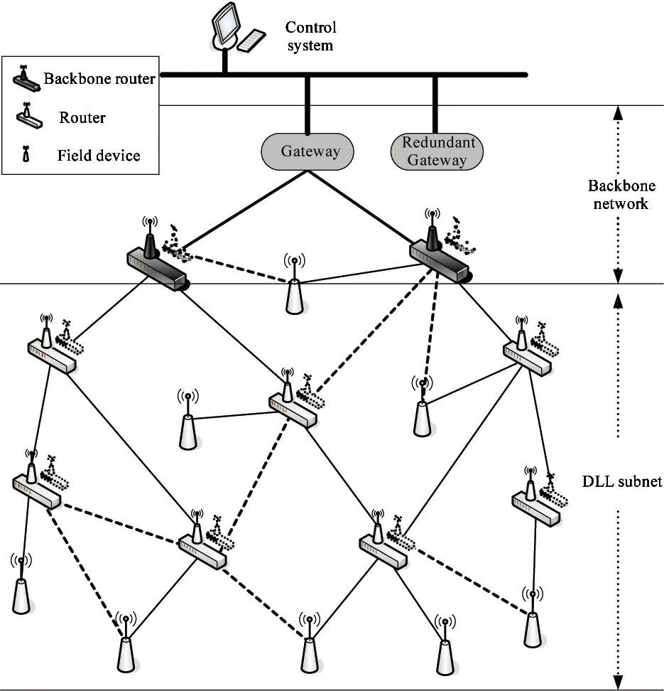
Fig.1 Network topology of ISA100.11a
1.2 Network function configuration
Devices in the ISA100.11a network can be divided into four types according to function: I/O device, router, gateway and host computer. The I/O device is configured with a wireless module and sensors (e.g., smoke sensor, gas sensor, temperature and humidity sensor). The wireless module transfers data which is collected by sensor to the router; The function of router is to forward data to gateway; Gateway plays the role of network manager and security manager, which processes and passes data to the host computer via Ethernet or serial; The host computer displays data in the interface, then people analyse all the state of data and control the industrial environment.
1.3 Superframe and timeslot
The main function of data link layer (DLSL) is to allocate communication resource to avoid conflict and improve the link throughput and bandwidth utilization. The involved concepts in data link layer include timeslot, superframe and link in ISA100.11a.
Timeslot is the smallest time unit of data transmission. The network administrator sets the length of timeslots when the device joins the network. Superframe is a set of recurring timeslot, the number of the timeslots determines the superframe cycle[10]. Link is used for communication between devices and includes time and frequency, and determines how an equipment occupies time slots to transmit data. There are three types of links: transmit link, receive link and idle link. Fig.2 is a superframe which cycle is 10 timeslots, the timeslot 1, 3, 6, 10 are links which keep idle; the timeslot 2, 4, 8 are links which are used to transmit data and timeslot 5, 7, 9 are used to receive data.

Fig.2 Time slot, superframe and links
1.4 The routing evaluation criteria
The target of routing algorithms is to select the path which spends the least amount of time to transfer data from initial node to terminal one. The data transfer time is mainly affected by the link quality and transmission delay in the network of ISA100.11a. In addition, the poor link quality causes packet loss and packet error which will lead data retransmission and retransmission delay. Data must be transmitted in arranged timeslot of superframe which will cause time delay[11]. Existing routing algorithms generally choose one of them as the routing criteria and the selected path may not be the optimal one. The algorithm in this paper chooses link quality and transmission delays as the routing criteria and considers the affect of the retransmission to the algorithm. The best communication path selected by the algorithm is not only the path selected which has the best link quality[12]but also has a reasonable transmission delay.
(1) The quality of link
Industrial wireless communication is susceptible to the interference of the external signal. The physical layer of ISA100.11a standard complies with IEEE 802.15.4 standard and works in the global 2.4GHz free frequency band and there are other wireless networks such as ZigBee, WIA-PA, WirelessHART and Bluetooth in the band. Unstable link quality leads to the failure of data transmission, main loss of packet and wrong packet. It is necessary for us to consider how to avoid signal interference in practical application and select efficient link. It is significant for the whole network to obtain communication efficiency and reliability.
(2) Transmission delay
System manager allocates timeslots to the devices to send data in specified timeslot. It will generate transmission delay[13]when sending data in superframe. The algorithm will define a thresholdTdfortransmissiondelayandchoosethepathwhichhaslesssumoftransmissiondelaythanthresholdTd.Fig.3illustratestheslotallocationandtransmissiondelayofthecommunicationlink.Thecycleofsuperframeis10timeslots,andtimeslot2isthecommunicationlinkfornodeAtosenddatatonodeBandthedatatransmissiongenerates2timeslotdelays.Inthesamewayaboutother links, there are two paths for nodeAto send data toB,p1=
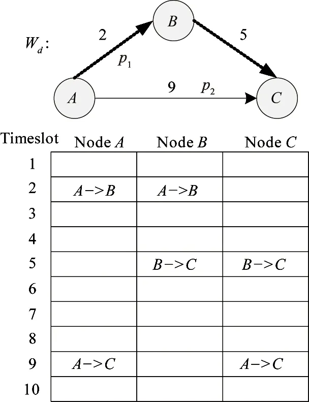
Fig.3 Timeslot allocation and timeslot delay
2 Thedesignofroutingalgorithm
2.1 Preprocessing of data
Link quality is the index of the data packet loss rate. It is the number of obtained data frames ratio to the sent data frames. The routing algorithm selects path based on the minimization of total weighting. The higher the initial link qualityqij(linkqualitybetweennodeitoj),thelowerQijafterpre-processis.Inordertomakethedataeasytobehandled.TheinitiallinkqualityqijispreprocessedinaccordancewithEq.(1)beforerunningthealgorithm,andtherelativelinkqualityQijisgotbyusinginverseproportionalfunction.
Qij=10(1-qij)
(1)
Lowlinkqualitycausesthefailureofdatatransmission,andthefailureofdatatransmissioncausesdataretransmissionwhichwillimpactontheroutingalgorithm.Fig.4isanexample,weightWqisusedforthetotallinkquality,therearetwopathsfromnode1to6:p1=<1, 2, 3, 6>,Wq1=Q12+Q23+Q36=9.7,p2=<1, 4, 5, 6>,Wq2=12.8,itisobviousthatthelinkqualityweightofpathP1isbetterthanp2accordingtotheminimalpathalgorithm,butthelinkqualitybetweennode2and3istoolowtosenddatasuccessfully.Theretransmissionwillincreasetimegreatly.Sooneshouldchoosepathp2tosenddata.
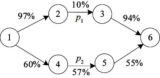
Fig.4 Weighted graph of link quality
In order to select the optima path and avoid the time delay caused by retransmission to affect the speed of data transmission, one needs to preprocess the total time delay between two nodes according to Eq.(2),
(2)
whereTdisthethresholdoftransmissiondelay,dijistransmissiondelayfromnodeitojandCisthetimeofdataretransmission(i.e.superframecycle),Dijisthetotaltransmissiondelaythatincludestransmissionandretransmissiondelay.Ifthelinkqualityislowerthanacertainratioq1(e.g.,q1=10%),Itisdifficulttosenddatasuccessfully,whichwillbediscardeddirectlybysettingthevaluetoTd.Ifthelinkqualityiswithinarangeofq1andq2(e.g., 10%, 90%),withtheincreasingofthelinkquality,thetotaltransmissiondelayisreducing.Thepacketlossrateissmallifthepathhashighlinkquality,andwecanignoretheimpactontheroutingalgorithm.AfterpreprocessingthepathwillgetanewtransmissiondelayDij.
2.2Descriptionofthealgorithm
InordertoresearchandanalysethealgorithmthispaperabstractsthenetworkofISA100.11aintoamathematicalmodel,andturnstheedgeofallthenodesfromthesourcenodetodestinationoneintotwoweightedgraphs.ThisworkusesweightWdforthetransmissiondelayofdeterministicschedulingandretransmissiondelay,andusestheweightWqforthelinkquality.
Operatingkshortest path algorithm[14]in weighted graphWq,thealgorithmwillgetapathduringeverycycletimeandobtaintheoptimal,suboptimum,third-optimumpathinturn.EachtimetakesthepathtotheweightedgraphWdtocalculatethetotalofalltransmissiondelayamongallnodesofthispath,andthencomparesitwithtransmissiondelaythresholdTdofwholenetworkscheduling.IfWtislessthanTd,whichindicatesthatthispathistheoptimalonewhichhasthebestqualityofthecommunicationlinkundertherequirementofdeterministicschedulingandthenstopsthekshortestpathalgorithm,andthispathistheoptimalcommunicationpath.Ifnot,continuetorunthealgorithmuntilthepathmeetstwometrics.
TheYenalgorithm[15]isusedtoselectkshortest path which is based on the A star search algorithm[16]. The following content introduces the Yen algorithm, assumingsis the initial node andtis the terminal one,vis one of nodes in pathpsv,pst=psv<>pvt.Assumingpkis thekshortest acyclic path from nodestot,p1,p2,p3, …,pkcanbeseenasatreeTkwhichrootnodeiss, and puts all the candidate path into setX.vis the deviation node ofpk.It’sthefirst(accordingtotheorderfromstot) node which is outside of treeTk-1,obviously,vis at least the second node ofpk,andthev’isthenodebehindvin the pathpk. The edge fromv’ tovis the deviation edge ofpk,andthepathfromnodev’totheterminalnodetisthedeviationpathofpk.TheconcretestepsofYenalgorithmaredescribedasfollows:
Firstonecancalculatep1whichistheshortestpathfromstoteasilybyDijkstra,Bellman-FordorBFSalgorithm,everytimewhenonecalculatespk,aquantityofcandidatepathsbasedonPkcanbedeveloped.TakingFig.5asanexample,theblacknodesformpathpk,uiisthenodebetweenv’andthepreviousnodeoftheterminalnodeinpk,u1=v’,u2=v,andsoon.Foreachnodeui,acandidatepathPk(ui,t) can be sought out, i.e., the path of dotted line in the figure which is the shortest path fromuitotexceptthepathinpk.Theselectionofpk(ui,t)mustmeetthefollowingconditions:
Condition1:Assumingui’isthenodeintreeTkwhichiscorrespondingtou,theedgestartingfromnodeuiinpathpk(ui,t)isnotthesamewithanyedgewhichstartsfromnodeu’inthetreeTk.ThisconditionensuresthatthecandidatepathsmustnotbethesamewithanypathinthetreeTk.
Condition2:Thenodesinpk(ui,t)exceptuicannotappearinpk(s,ui).Thisconditionensuresthecandidatepathhasnotanyloop.

Fig.5 Candidate path
1Routing algorithm based on k shortest path:
2 Find the shortest pathp1andsetk=1;
3Putp1into{T1};
4Calculatethetransmissiondelayofp1:Wd;
5 While (Wd>=Td)
6Definev,v’;
7 For each nodeui∈{v’,v, …,t}
8 If {edge
9 Get the candidate pathpk(ui)=pk(s,ui) +pk(ui,t);
10Puteachpk(ui)into{X};
11 If {Tk} ≠Ø
12 The optimal path of {X}ispk+1;
13 End If
14 End If
15 Remove thepk+1inthe{X}andputitinto{Tk};
16Tk=Tk+1;
17k=k+1;
18 End For
19 Calculate the transmission delay ofpk+1;
20 End
Ifpk(ui,t)meetstheconditions,anewcandidatepathPk(ui)isfound,whichispk(s,ui)connectingtopk(ui,t).
Choosingallthecandidatepathpk(ui)ofpkandputtingthemintocandidatepathssetX,onecangettheoptimalpathinthesetXas the pathpk+1.Deletethepathpk+1fromT1andputitintothedeviationtreeTktoformanewtreeTk+1.
3 Performanceevaluation
3.1 Examples of routing algorithm
The following three figures show an example of routing algorithm, Fig.6 shows thekshortest path from initial node 1 to terminal node 12 obtained by operating the routing algorithm, Fig.7 shows the weighted graph of network, and Fig.8 shows the procedure the algorithm operates. ThresholdTdoftransmissiondelayissetto20slots,thecycleofdataretransmissionCis 8 slots,q1,q2ofEq.(2)are10%and90%.

Fig.6 kshortest path of network
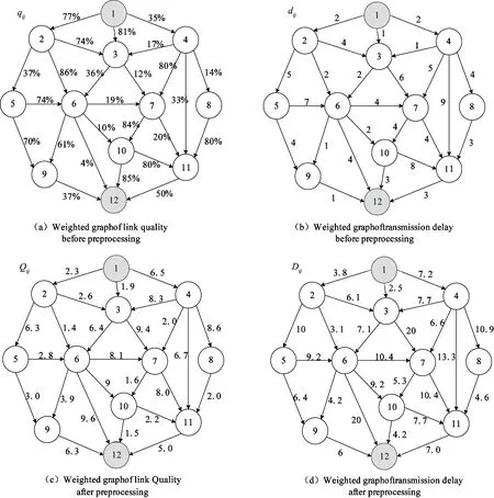
Fig.7 Weighted graph of routing algorithm
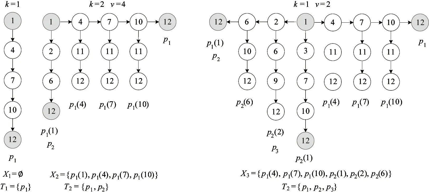
Fig.8 The procedure to obtain the best path
(1)UsingtheDijkstraalgorithmtoobtainoptimalpathp1=<1, 4, 7, 10, 12>frominitialnode1toterminalnode12,k=1.Wecanfigureouttheweightofthelinkqualityandthetransmissiondelayofpathp1,Wq= 11.6,Wd= 23.3,Wd>Td,whichcan’tmeetthecondition.Putp1intothedeviationtreeT1thencontinuetooperationthealgorithm.Thedeviatenodeofp1isnode4.
Theresultisthat:k=1,p1=<1,4,7,10,12>,v=4,T1={p1},X1=Ø.
(2) Calculate the candidate paths based on pathp1andputthemintosetX,wherep1(1)=<1, 2, 6, 12>,Wq=13.3;p1(4)=<1, 4, 11, 12>,Wq=18.2;p1(7)=<1, 4, 7, 11, 12>,Wq=21.5;p1(10)=<1, 4, 7, 10, 11, 12>,Wq=17.3.X2={p1(1),p1(4),p1(7),p1(10)},Thebestpathp1(1)inX2isselectedasthesecondoptimalpathwhichhasthebestlinkquality,p2=p1(1)=<1, 2, 6, 12>,buttheretransmissiondelayfromnode6tonode12isverybigbecauseofitsrelativelylowlinkquality,therefore,wediscardpathp2directly.Deletep1(1) fromX2and put it into the deviation treeT2. The deviate node is node 2.
The result is that:k=2,p2=<1, 2, 6, 12>,v=2,T2={p1,p2},X2={p1(4),p1(7),p1(10)}.
(3)Similarly,calculatethecandidatepathsbasedonpathp2andputthemintosetX,p2(1)=<1, 3, 7, 10, 12>,Wq=14.4;p2(2)=<1, 2, 6, 9, 12>,Wq=13.3,p2(6)=<1, 2, 6, 10, 12>,Wq=14.2;X3={p1(4),p1(7),p1(10),p2(1),p2(2),p2(6) }.Thebestpathp2(6)inX3issetectedasthethirdoptimalpathp3=p2(6)=<1, 2, 6, 9, 12>.Calculateandjudgethetransmissiondelayofp3inweightedgraphWd,Wd=17.1,Wd
3.2Vertificationresults
TheroutingalgorithmverificationsystemisbuiltbasedonlaboratoryresourcesandoperatedalgorithmintheISA100.11aprotocolstacktotestitsperformance.ThetestsystemoperatingthealgorithminthewirelessmodulesbasedonCC2530chip.Fig.9showsthenetworkofISA100.11athatincludesagateway,severalroutersandterminalnodes.
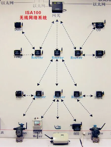
Fig.9 Testing system
The routing algorithm of this paper uses link quality as the route criterion to select the optimum communication path, and then calculate whether the timeslot latency of deterministic scheduling and retransmission delay meet the requirements of network. In order to analyze the performance of routing algorithm, it is compared with the other three algorithms, in which the first algorithm selects transmission delay and link quality as the routing criterion, but the data retransmission is not taken into account; the second algorithm selects link quality and the third selects transmission delay as the routing criteria. The verification system establishes four different ISA100.11a networks and the number of nodes are 10, 15, 20 and 25, respectively, and operates the different routing algorithms in the network of certain numbers of nodes and compares the performance of algorithms by the data transfer time of different paths selected by the algorithms.
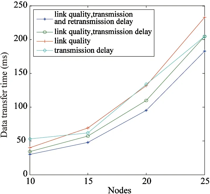
Fig.10 Data transfer time contrast of different algorithm
The four routing algorithms are operated in the network of different number nodes to obtain four optimal communication paths from source node to the destination. Fig.10 shows the average data transfer time contrast of four paths selected by different algorithms, wherein the abscissa represents the number of nodes on different networks and the ordinate values represents the average data transfer time of four paths. It can be seen in Fig.10 that only choosing transmission delay or link quality as routing criterion will generate bigger data transfer time, because the paths selected by algorithms may have poor link quality or the biggish scheduling time. Routing algorithm uses transmission delay and link quality as the criteria to obtain better path quality but the data retransmission is not taken into account, therefore, the path may have poor link quality between some nodes. The path of proposed routing algorithm comparing with other algorithms requires less data transfer time and better performance.
Four routing algorithms are run in the ISA100.11a network that has 20 nodes, and the average data transfer time of four paths selected by different algorithms at different values ofkare contrasted. As shown in Fig.11, generally the optimum communication path can be got when thekvalue is less than 3, and the path selected when thekvalue is 1 maybe not the optimum path. It’s necessary to select multiple routing criteria to balance the effects of different factors on the routing algorithm. After the routing algorithm obtains the optimal path, data transfer time increases withkvalue. The results conclude that the algorithm considering the transmission delay and link quality and retransmission has better performance under the same conditions and the algorithm proposed in this paper is superior to others obviously and has certain advantages.
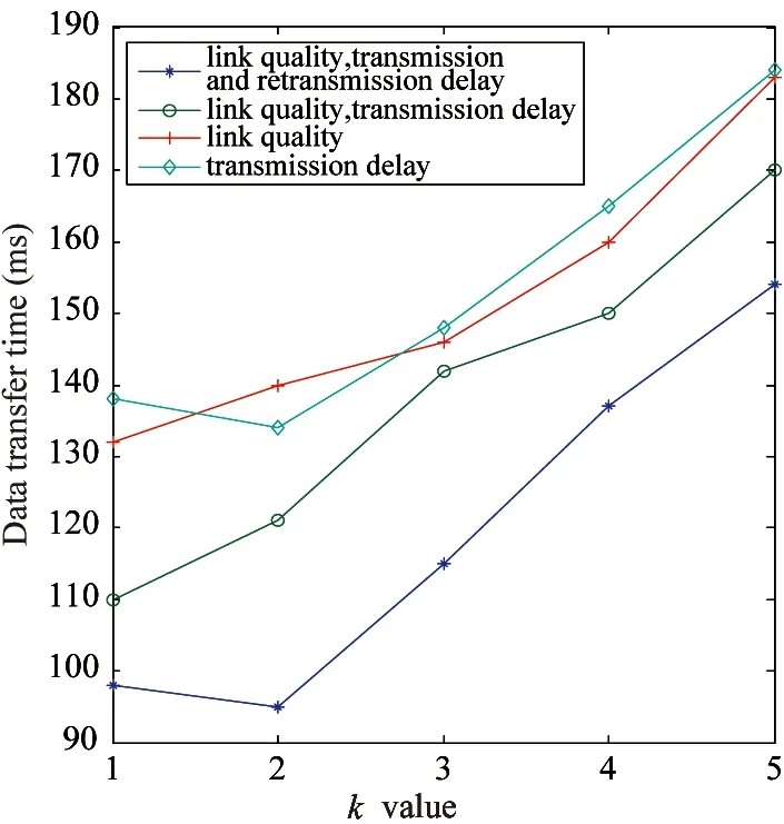
Fig.11 Data transfer time contrast of different algorithm
4 Conclusion
This paper investigates the deterministic scheduling technology of industrial wireless network standard ISA100.11a and designs a routing algorithm for industrial environments according to network standards and characteristics. Routing algorithms take into account the link quality, schedule delays and data retransmission and uses thekshortest path algorithm to obtain the optimal path. the proposed algorithm is compared with other algorithms under different routing criteria, the results show that the routing algorithm designed in this work can operate stably and reliably in ISA100.11a stack and the optimal path selected by the routing algorithm not only has high channel quality and small retransmission delay, but also meets the requirements of the deterministic scheduling. It can effectively solve the problem of packet loss and transmission delay, and provides a solution to realize efficient data transmission.
[1] Gungor V C, Hancke G P. Industrial wireless sensor networks: Challenges, design principles, and technical approaches.IndustrialElectronics, 2009, 56(10): 4258-4265
[2] Saleem M, Di Caro G A, Farooq M. Swarm intelligence based routing protocol for wireless sensor networks: Survey and future directions.InformationSciences, 2011, 181(20): 4597-4624
[3] Chowdhury K R, Akyildiz I F. CRP: A routing protocol for cognitive radio ad hoc networks.SelectedAreasinCommunications, 2011, 29(4): 794-804
[4] Taneja S, Kush A. A Survey of routing protocols in mobile ad hoc networks.InternationalJournalofInnovation,ManagementandTechnology, 2010, 1(3): 2010-0248
[5] Zaharia M, Keshav S, Gossip-based search selection in hybrid peer-to-peer networks.ConcurrencyandComputation:PracticeandExperience, 2008, 20(2): 139-153
[6] Perkins C E, Royer E M, Das S R, et al. Performance comparison of two on-demand routing protocols for ad hoc networks.PersonalCommunications, 2001, 8(1): 16-28
[7] Dinh N Q, Kim D S. Performance evaluation of priority CSMA-CA mechanism on ISA100. 11a wireless network.ComputerStandards&Interfaces, 2012, 34(1): 117-123
[8] Petersen S, Carlsen S. WirelessHART versus ISA100. 11a: the format war hits the factory floor.IndustrialElectronicsMagazine,IEEE, 2011, 5(4): 23-34
[9] Wireless Systems for Industrial Automation: Process Control and Related Applications, ISA Std.100.11a, 2011
[10] Wang P, Wang Q, Wang H. Overview and Analysis of the Industrial Wireless Technology ISA100.11a.CinaInstrumentation, 2009 (10): 59-63
[11] Gallager R G. A minimum delay routing algorithm using distributed computation.Communications, 1977, 25(1): 73-85
[12] Kuo Y L, Wong K L. Printed double-T monopole antenna for 2.4/5.2 GHz dual-band WLAN operations.AntennasandPropagation,IEEETransactionson, 2003, 51(9): 2187-2192
[13] Xiao Y, Rosdahl J. Throughput and delay limits of IEEE 802.11.IEEECommunicationsSociety, 2002, 6(8): 355-357
[14] Yen J Y. Finding the k shortest loopless paths in a network.ManagementScience, 1971, 17(11): 712-716
[15] Shier D R. On algorithms for finding the k shortest paths in a network.Networks, 1979, 9(3): 195-214
[16] Chabini I, Lan S. Adaptations of the A* algorithm for the computation of fastest paths in deterministic discrete-time dynamic networks.IntelligentTransportationSystems, 2002, 3(1): 60-74
Wang Ping, born in 1963. He received his Ph.D degrees in Southwest Jiaotong University in 1994. Now he is a professor in Chongqing University of Posts and Telecommunications and the dean of Automation. His main research interests include cooperative communications, wireless communication systems and protocols, wireless sensor networks and wireless industrial networks.
10.3772/j.issn.1006-6748.2015.01.007
*Supported by the National Natural Science Foundation of China (No.61301125), the National High Technology Research and Development Programme of China (No.0AA0401028003), National Science and Technology Major Project (No.2013ZX03005005), the Fundamental and Advanced Research Program of Chongqing (No.cstc2013jcyjA40008) and the Youth Top-notch Talent Support Program of Chongqing (No.2013-139).
*To whom correspondence should be addressed. E-mail: wangping@cqupt.edu.cnReceived on Jan. 24, 2014
 High Technology Letters2015年1期
- High Technology Letters的其它文章
- Maneuvering target tracking algorithm based on cubature Kalman filter with observation iterated update*
- Realization of a tunable analog predistorter using parallel combination technique for laser driver applications*
- Data organization and management of mine typical object spectral libraries*
- Retrieval and analysis of sea surface air temperature and relative humidity*
- Filtered-beam-search-based approach for operating theatre scheduling*
- Research on assessing compression quality taking into account the space-borne remote sensing images*
