Brillouin optical time-domain analysis for geotechnical monitoring
L.Zeni,L.Pirelli,B.Avolio,A.Cosett,R.Pp,G.Zeni,C.Di Mio, R.Vssllo,A.Minro
aDIII,Second University of Naples,Aversa,Italy
bInstitute for Electromagnetic Sensing of the Environment(IREA),National Research Council,Napoli,Italy
cDICDEA,Second University of Naples,Aversa,Italy
dSchool of Engineering,University of Basilicata,Potenza,Italy
Brillouin optical time-domain analysis for geotechnical monitoring
L.Zenia,b,*,L.Picarellic,B.Avolioc,A.Coscettaa,R.Papac,G.Zenib,C.Di Maiod, R.Vassallod,A.Minardoa
aDIII,Second University of Naples,Aversa,Italy
bInstitute for Electromagnetic Sensing of the Environment(IREA),National Research Council,Napoli,Italy
cDICDEA,Second University of Naples,Aversa,Italy
dSchool of Engineering,University of Basilicata,Potenza,Italy
A R T I C L EI N F O
Article history:
Received 30 November 2014
Received in revised form
8 January 2015
Accepted 26 January 2015
Available online 9 May 2015
Brillouin optical time-domain analysis
(BOTDA)
Tunnel engineering
Deformation
Distributed monitoring
Health diagnosis
In this paper,we show some recent experimental applications of Brillouin optical time-domain analysis (BOTDA)based sensors for geotechnical monitoring.In particular,how these sensors can be applied to detecting early movements of soil slopes by the direct embedding of suitable fber cables in the ground is presented.Furthermore,the same technology can be used to realize innovative inclinometers,as well as smart foundation anchors.
©2015 Institute of Rock and Soil Mechanics,Chinese Academy of Sciences.Production and hosting by Elsevier B.V.All rights reserved.
1.Introduction
Distributed fber-optic strain sensors have great potentialities in the feld of geotechnical monitoring(Dewynter et al.,2009; Olivares et al.,2009;Iten,2011;Minardo et al.,2014).By integrating a single fber-optic cable into soil or a geotechnical work,a large number of accurate,spatially resolved data can be obtained. The Brillouin optical time-domain analysis(BOTDA)method allows for strain measurements in the microstrain range,with a typical spatial resolution of 1 m and a maximum sensing range of 50 km. This means that thousands of“strain gauges”along a single cable connected to structures,embedded in soil or grouted into boreholes,for example,can provide information about the current state of the object under supervision.The objects can include geological and civil structures,such as a construction site,a tunnel,a landslide prone area,or a pipeline.It is evident that such a technology implies a beneft for placing fber-optic cables anywhere possible on construction sites and in the green feld(Minardo et al.,2012).
This paper summarizes some results of experiments carried out byresearch staff at Second University of Naples.Inparticular,aftera brief description of the sensor technology,three applications of the BOTDA technology in the geotechnical feld will be described:(a) slope monitoring by optical fbers embedded into the soil;(b) detection of soil movement by use of an optical fber based inclinometer;(c)monitoring of a ground anchor by use of an embedded optical fber.
2.Principle of operation of BOTDA
The experimental results reported in this paper have been conducted exploiting stimulated Brillouin scattering(Boyd,2008)in single-mode optical fbers.In brief,two counter-propagating lightwaves exchange energy along the fber,in a measure depending on their frequency offset.If the offset falls within a specifc range,the radiation at higher frequency(pump wave)transfers energy to that at lower frequency(Stokes wave).The sensing principle is based on the fact that the frequency difference at which the maximum amplifcation of the Stokes wave occurs,known as Brillouin frequencyshift(BFS),variesdependingonthemechanicalandthermal states of the fber.In particular,the BFS increases with both temperature and strain.Spatial resolution,i.e.the ability to measure deformation and temperature changes in a distributed way,can be achieved through the use of a pulsed pump beam:in this way,the interaction takes place along successive sections of the fber as the pump pulse propagates down the sensing cable.By recording the intensity of the Stokes radiation as a function of time,the Brillouin gaincanbetracedineachsection.Themeasurementof theBrillouin gain as a function of time and frequency allows the entire profle ofBrillouin shift along the fber to be obtained,which in turn can be translated in terms of deformation or temperature through the use of appropriate calibration coeffcients.
Fig.1 shows the basic confguration employed for BOTDA.The pulsed and continuous wave(CW)beams are generated by two separated sources having lasing frequenciesν0andν0±νB,shifted by a defnite quantity in the range of the Brillouin frequency shift of the sensing fber.Fig.1 shows that the amplifcation of the Stokes beam occurs at those locations where the frequency offset with the crossing pulse matches the local Brillouin frequency shift,which in turn is related to the temperature(or strain)of the analyzed fber coil.More in general,Brillouin time-domain signals are acquired in BOTDA systems for a range of frequency offsets,so as to get a full picture of the Brillouin frequency shift at each location.
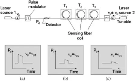
Fig.1.Basic confguration for BOTDA:(a),(b)and(c)show the waveform of optical power at detector(Pd),acquired when the frequency offset between the two lasers is tuned to the Brillouin frequency shiftνBof fber coils 1,2 and 3,placed at temperaturesT1,T2andT3,respectively.
3.Experiments on small-scale model slopes
The main requirements of monitoring systems in areas susceptible to sudden and rapid landslides should be the following:(a) a cheap and reliable instrumentation;(b)continuous monitoring in time and space;(c)low probability of error to avoid false or missed alarms.
For their ability to measure strainwith spatial continuity,optical fbers are particularly attractive.For this reason,we decided to check their performance in the monitoring of slopes in loose unsaturated granular soils susceptible to catastrophic rainfall-induced fowslides.The basic idea is that a sensing fber buried in the soil can detect the deformation due to ongoing volumetric and/or shear strains induced by the decrease in suction,which can be interpreted as a warning of incoming failure.The capability of the fber to provide distributed strain readings should allow to detect ongoing deformation at any point of even very long slope sections. This is a fundamental advantage with respect to conventional monitoring devices(topographic readings,inclinometers,etc.) which can provide information only at specifc points.The low cost of fbers is another relevant advantage.
This simple idea suggested an experimental program to test this new kind of sensors in small-scale model slopes subjected to artifcial rainfall.The slopes are made of volcanic ash laid down into a fume imposing the same porosity as in the feld.The water infltration induced by artifcial rain causes an increase in the water content and a decrease in suction and,consequently,volumetric and shear strains;this mechanical process can lead to slope failure. The basic equipment for monitoring includes tensiometers,pore pressure transducers,laser displacement transducers,electrical moisture probes(TDRs)and video-cameras(see Fig.2).For the present application the fume was tilted with an inclination of 40°, and equipped with tensiometers,displacement sensors and optical fbers.The latter was a tight-buffer standard single-mode fber for telecommunications having an overall diameter of 900μm.The optical fber sensor was buried into the ground along two alignments parallel to each other(Fig.2).The model slopes,as a proof of principle,have been made up with volcanic ashes taken from the site of Cervinara,Italy,where feld monitoring is being carried out (Pirone et al.,2012).The slope has a length of 1.35 m,thickness of 10 cm,initial water content ranging between 43%and 50%,and porosity close to the feld value(70%-76%).
In the experiment,a system of anchoring constituted by small plastic grids glued every 20 cm at the fber was adopted,as shownin Fig.3a.Fig.3b shows the position of the tensiometers and of the laser displacement sensors.
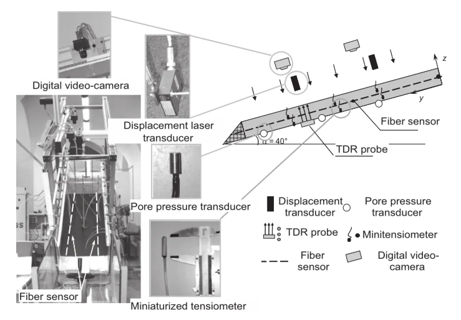
Fig.2.The instrumented fume.
The readings of the optical fber sensorare reported in Fig.4.The increase in Brillouin frequency shift from the initial profle(t=0), which reveals a state of stress due to accumulated strains during a frst test stage not reported here,to the latest one(t=47 min),is about 200 MHz.This corresponds to a deformation of about 0.4%. The collapse of the slope occurs after 50 min.Readings recorded after failure(t>tf)show that the Brillouin frequency shift returns to its initial value.
For the sake of comparison,the readings of the tensiometers and displacement sensors are reported in Figs.5a and b,respectively.As it can be seen from Fig.5,the soil is completely saturated at surface before any settlement begins,while the saturation of the deep layer is complete only when a vertical displacement of the soil of a few millimeters is recorded.On the other hand,the optical fber sensors,being deployed in order to detect the soil sliding,start measuring a signifcant tensile strain when the early signs of the slope sliding occur.

Fig.3.(a)Sensing fber anchored to the soil deposit.(b)Position of the tensiometers (T)and displacement sensors(L).
4.Optical fber inclinometer
An inclinometer based on BOTDA has been devised and realized. Its main characteristics can be summarized as follows:(a)measurement of three-dimensional(3D)deformation of soil;(b) continuous monitoring from a remote site and multiplexing capability;(c)self-compensation against temperature variations;(d) displacement sensitivity as high as 1 mm over 1 m;(e)safe operation up to overall displacements as large as 15 cm over 1 m,the limit being posed just by the breaking of the sensing optical fber.
It should be emphasized that the above characteristics are not fulflled by traditional inclinometers which usually require periodic inspections for interrogation,and become useless if the displacement reaches values as large as to prevent the sliding of the measuring head along the inclinometer tube itself(a few centimeters of movement across a narrow slip plane).
The optical fber inclinometer is realized by epoxy-gluing four equally spaced fbers along the surface of a PVC pipe for its entire length,as shown in Fig.6.
The pipe is 50 mm in diameter,and 3.2 mm in thickness,while its overall length is 750 cm,achieved by connecting three pipe sections of 250 cm.The measurement of the strain profles along the fbers allows the reconstruction of the 3D deformation of the pipe and,consequently,the movements of the soil wherethe pipe is embedded(Lenke et al.,2011).
In order to assess the validity of the proposed approach,several laboratory tests were performed on the inclinometer tube before on-site installation.Fig.7a shows the selection of the results achieved during the laboratory tests.In detail,we show the vertical displacement along a 180 cm-long pipe,with identical crosssection of the pipe used on-site,subjected to prescribed displacement at one end and fxed on the other end.The displacements retrieved by the optical fber sensor using a Brillouin shift sensitivity to strain of 417 MHz/%and a spatial resolution of 20 cm,are compared to the ones provided by eight dial gauges distributed along the pipe.It is seen that the agreement is remarkably good.In particular,the maximum deviation between the dial gauge and optical fber displacement was about 4 mm,while the standard deviation of the measurement error was about 1 mm.Note that the observed discrepancy is coherent with an error analysis of the displacement.In fact,assuming a strain uncertaintyσε=100με,we can calculate the standard deviation of the displacement simply bywhereLandDrepresentthe pipe length and diameter,respectively; Δzis the spatial resolution.This equation shows that the variance of displacement grows with the pipe length,thus the proposed method may suffer from inaccuracies for relatively long pipes.


Fig.4.Temporal sequences of the Brillouin shift along the fber.

Fig.5.(a)Suctionua-uw,whereuaanduware the air pressure and the pore water pressure,respectively.(b)Vertical displacementuz.
In regard to on-site measurement results,the selected test site was an area,located in Basilicata Region,Italy,subjected to slowsoil movements and already instrumented with traditional inclinometer tubes.The test site is depicted in Fig.8,where the positions of the traditional inclinometers and the fber optic one are shown,as well.
The optical fber inclinometer was installed in a 750 cm deep borehole which was then flled with grout.After allowing the grout cure for one month,a frst measurement was performed as a reference in order to eliminate all the strain induced by the installation procedure.
The subsequent measurements allow the detection of any soil movements.Fig.9 shows the obtained results.Despite its limited length,the fber optical inclinometer exhibits a suffcient accuracy in detecting the maximum pipe displacement at the ground surface.
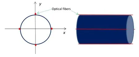
Fig.6.The optical fber inclinometer tube.
5.A“smart”foundation anchor
For this experiment,a smart foundation anchor was devised and realized.The main objective of this activity was to improve the understanding of the anchor’s load bearing behavior,as the performance of the anchor is limited by the effciency of load transfer from the anchor tendon to the soil via the grout(Iten, 2011).
In brief,the anchor was equipped with an optical fber epoxyglued inside the steel tendon.The optical fber was disposed in a loop confguration so as to have both ends available for BOTDA distributed strain measurements.A special optical fber cable with 3.2 mm outer diameter,produced by Brugg Kabel AG,was selected for the tests(V1 cable).
After realization,the anchor was feld-installed in Campania Region,Italy.Distributed strain measurements were taken at each loading step.The results are summarized in Figs.10 and 11.Note that the symmetrical appearance of the various strain profles is due to the fact that the same fber was running twice along the cable.We observe a number of signifcant features:(a)the strain decreases linearly from the ground level,vanishing at the deepest end of the cable:this means that the whole cable length is involved in transferring the pullout force into the soil;(b)at larger displacement steps,the strain profle propagates behind the fxationpoint due toslippage of the glass fber inside the protection;(c) comparing Figs.10 and 11,it is seen that there is a signifcant residual strain along the fber at the end of the pullout test:for example,during the unloading phase a load of 100 kN produces a maximum strain of about 1000με,equivalent to the strain observed during the loading phase for a load of 350 kN.

Fig.8.Test site in Basilicata Region,Italy.S9F:fber optic inclinometer;I9B,I9C: traditional inclinometers.

Fig.7.Comparison between the displacements provided by the optical fber sensor (solid lines)and the ones provided by the dial gauges(squares).δrepresents the maximum displacement applied at the free end.
6.Conclusions
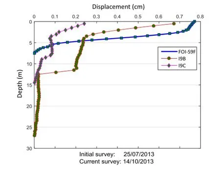
Fig.9.Displacement of the optical fber inclinometer(FOI-S9F)as a function of depth, and comparison with the readings of two traditional inclinometers:the I9B(depth: 27 m)and the I9C(depth:15 m)(after Minardo et al.,2014).
Different applications of BOTDA based optical fber distributed sensors to geotechnical monitoring have been reported.Laboratoryand feld tests have shown the great potentialities of such sensors in monitoring and analyzing soil slopes and foundations.The main limitations of the proposed technology in geotechnical monitoring are essentially the lack of standardized procedures for sensing cables installation in large areas,the diffculty in data interpretation and accurate modeling of ground/sensor interaction.
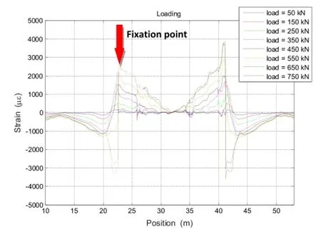
Fig.10.Strain measurements during the loading phase.

Fig.11.Strain measurements during the unloading phase.
Confict of interest
The authors wish to confrm that there are no known conficts of interest associated with this publication and there has been no signifcant fnancial support for this work that could have infuenced its outcome.
Acknowledgments
It is gratefully noted that the project is supported by grant from MIUR-PON01 1525-MONICA.
Boyd RW.Nonlinear optics.3rd ed.Waltham,Massachusetts,USA:Academic Press; 2008.
Dewynter V,Rougeault S,Magne S,Ferdinand P,Vallon F,Avallone L,Vacher E,De Broissia M,Ch Canepa,Poulain A.Brillouin optical fber distributed sensor for settlement monitoring while tunneling the metro line 3 in Cairo,Egypt.In: Proceedings of the SPIE 7503,20th International Conference on Optical Fibre Sensors,75035M;2009.http://dx.doi.org/10.1117/12.835376.
Iten M.Novel applications of distributed fber-optic sensing in geotechnical engineering.Zurich,Switzerland:vdf Hochschulverlag AG;2011.
Lenke P,Wendt M,Krebber K,Glötzl R.Highly sensitive fber optic inclinometer: easy to transport and easy to install.In:Proceedings of the SPIE 7753,21st International Conference on Optical Fiber Sensors,775352;2011.http:// dx.doi.org/10.1117/12.884695.
Minardo A,Bernini R,Amato L,Zeni L.Bridge monitoring using Brillouin fber-optic sensors.IEEE Sensor Journal 2012;12(1):145-50.
Minardo A,Picarelli L,Avolio B,Coscetta A,Papa R,Zeni G,Di Maio C,Vassallo R, Zeni L.Fiber optic based inclinometer for remote monitoring of landslides:on site comparison with traditional inclinometers.In:Proceedings of International Geoscience and Remote Sensing Symposium(IGARSS 2014)/35th Canadian Symposium on Remote Sensing(35th CSRS),Québec City,Québec,Canada; 2014.p.4078-81.
Olivares L,Damiano E,Picarelli L,Greco R,Bernini R,Minardo A,Zeni L.An instrumented fume for investigation of the mechanics of rainfall-induced landslidesinunsaturatedgranularsoils.GeotechnicalTestingJournal 2009;32(2):108-18.
Pirone M,Damiano E,Picarelli L,Olivares L,Urciuoli G.Groundwater-atmosphere interaction in unsaturated pyroclastic slopes at two sites in Italy.Rivista Italiana di Geotecnica 2012;3:29-49.

Luigi Zeniis full professor of electronics and photonics at the Second University of Naples and president of the Research Consortium on Advanced Remote Sensing Systems-CO.RI.S.T.A.(www.corista.eu).He has been,from 2001 to 2012,vice-director of the Department of Information Engineering.He took his degree in Electronic Engineering,summa cum laude,from University of Naples in 1988 and his Ph.D.in Electronics and Computer Science in 1992.He worked at TU-DELFT(NL)as a visiting scientist. He has been national coordinator of PRIN projects,scientifc coordinator of research contracts with public and private institutions and responsible for projects funded within the 7th FP of the EU.He has been member of the Management Committee of the COST 299“Optical fbers for new challenges facing the information society”and of the COST TD1001“Novel and Reliable Optical Fiber Sensor Systems for Future Security and Safety Applications”. His main research interests include optical fber sensors for distributed measurements of deformation and temperature,optoelectronic integrated sensors and biosensors.He is author of about 120 papers published in international journals,120 publications at international conferences and 10 patents.He is also founder of the Spin-Off company OPTOSENSING dealing with structural and environmental monitoring by optical fber sensors.
*Corresponding author.Tel.:+39 0815010269.
E-mail address:luigi.zeni@unina2.it(L.Zeni).
Peer review under responsibility of Institute of Rock and Soil Mechanics,Chinese Academy of Sciences.
1674-7755©2015 Institute of Rock and Soil Mechanics,Chinese Academy of Sciences.Production and hosting by Elsevier B.V.All rights reserved.
http://dx.doi.org/10.1016/j.jrmge.2015.01.008
 Journal of Rock Mechanics and Geotechnical Engineering2015年4期
- Journal of Rock Mechanics and Geotechnical Engineering的其它文章
- Book review
- Editorial
- Detecting and monitoring of water inrush in tunnels and coal mines using direct current resistivity method:A review
- Effects of sample dimensions and shapes on measuring soil-water characteristic curves using pressure plate
- The use of point load test for Dubai weak calcareous sandstones
- Surface wave propagation effects on buried segmented pipelines
