
Numerical simulation of fow past twin near-wall circular cylinders in tandem arrangement at low Reynolds number
2015-01-16 01:21:17GuoqingTngChunqiChenMingZhoLinLu
Water Science and Engineering 2015年4期
Guo-qing Tng,Chun-qi Chen,Ming Zho,Lin Lu,*
aState Key Laboratory of Coastal and Offshore Engineering,Dalian University of Technology,Dalian 116024,PR China
bSchool of Computing,Engineering and Mathematics,University of Western Sydney,Penrith 2751,NSW,Australia
Numerical simulation of fow past twin near-wall circular cylinders in tandem arrangement at low Reynolds number
Guo-qiang Tanga,Chuan-qi Chena,Ming Zhaob,Lin Lua,*
aState Key Laboratory of Coastal and Offshore Engineering,Dalian University of Technology,Dalian 116024,PR China
bSchool of Computing,Engineering and Mathematics,University of Western Sydney,Penrith 2751,NSW,Australia
Fluid fow past twin circular cylinders in a tandem arrangement placed near a plane wall was investigated by means of numerical simulations. The two-dimensional Navier-Stokes equations were solved with a three-step fnite element method at a relatively low Reynolds number ofRe=200 for various dimensionless ratios of 0.25≤G/D≤2.0 and 1.0≤L/D≤4.0,whereDis the cylinder diameter,Lis the center-to-center distance between the two cylinders,andGis the gap between the lowest surface of the twin cylinders and the plane wall.The infuences ofG/DandL/Don the hydrodynamic force coeffcients,Strouhal numbers,and vortex shedding modes were examined.Three different vortex shedding modes of the near wake were identifed according to the numerical results.It was found that the hydrodynamic force coeffcients and vortex shedding modes are quite different with respect to various combinations ofG/DandL/D.For very small values ofG/D,the vortex shedding is completely suppressed,resulting in the root mean square(RMS)values of drag and lift coeffcients of both cylinders and the Strouhal number for the downstream cylinder being almost zero.The mean drag coeffcient of the upstream cylinder is larger than that of the downstream cylinder for the same combination ofG/DandL/D.It is also observed that change in the vortex shedding modes leads to a signifcant increase in the RMS values of drag and lift coeffcients. ©2015 Hohai University.Production and hosting by Elsevier B.V.This is an open access article under the CC BY-NC-ND license(http:// creativecommons.org/licenses/by-nc-nd/4.0/).
Navier-Stokes equations;Finite element method;Circular cylinder;Vortex shedding mode;Hydrodynamic force coeffcient
1.Introduction
Steady fuid fows past circular cylinders near a plane wall are highly signifcant to ocean currents over submarine pipelines.Actual pipelines may be close to one another in a tandem arrangement,due to special engineering requirements, leaving a certain center-to-center distance between them.The gap between the pipelines and the plane wall can also be formed by either an uneven seabed or local scour below submarine pipelines,which can be measured using thedistance from the seabed to the lowest surface of pipes.These suspended pipelines are subjected to oscillating fuid forces induced by vortex shedding,which may give rise to severe vortex-induced vibration and even strengthen the undesirable local scour.Hence,an understanding of hydrodynamic characteristics is important to practical pipeline design,even if the fow is limited to a rather low Reynolds number(Re).
Investigations of fuid fow past a pair of cylinders in tandem,side-by-side,or staggered arrangements have been carried out in the past,and these investigations have mainly focused on situations in which the cylinders were immersed in an open space and the effect of wall boundaries could be ignored.Zdravkovich(1977,1987)showed that when more than one body is placed in a fuid fow,the resulting hydrodynamic force coeffcient and vortex shedding mode may be completely different from those on a single body at the same Reynolds number.Hence,a variety of vortex shedding modes,characterized by the different characteristics of near wakes, should be discerned under different arrangements of the circular cylinders or spacings between two circular cylinders.
Flow past two circular cylinders of an identical diameter in a side-by-side confguration was studied by Bearman and Wadcock(1973),Williamson(1985),and Kim and Durbin (1988).Their results showed that only one vortex shedding mode was observed when the distance ratioL/D≤2.0,whereLis the center-to-center distance between the two cylinders, andDis the cylinder diameter.Early experimental studies on the fow past circular cylinders in a tandem arrangement,for example,Ishigai et al.(1972),Kostiˊc and Oka(1972),Tanida et al.(1973),and King and Johns(1976),showed that there were two major fow regimes.For cylinders separated from one another at small values ofL/D,the fow is separated from the upstream cylinder and reattaches to the downstream one, while when the values ofL/Dare large,vortices are shed from both the cylinders.Meneghini et al.(2001)and Jester and Kallinderis(2003)studied the fow past two cylinders in tandem and side-by-side arrangements.Meneghini et al.(2001) observed negative drag coeffcients of the downstream cylinder forL/D≤4.0 andRe=200 when the two cylinders were in a tandem arrangement.Mittal et al.(1997)conducted numerical simulations to study fuid fows past two cylinders in tandem and staggered arrangements.They found that,for the two cylinders in a tandem arrangement,the hydrodynamic force coeffcient and vortex shedding mode were greatly dependent on the Reynolds number,in comparison to fuid fow past an isolate cylinder.
Flow past a circular cylinder near a plane wall has also been widely studied in the past few decades.Investigations have shown that the vortex shedding can be suppressed with very small gaps between the cylinder and the plane wall.Under the condition of high Reynolds numbers in the sub-critical regime, Bearman and Zdravkovich(1978),Grass et al.(1984),and Lei et al.(1999)confrmed that the vortex shedding can be suppressed when the gap ratioG/D<0.3,although different experimental techniques were employed.Price et al.(2002) experimentally studied the fuid fow past a circular cylinder near a plane wall for Reynolds numbers between 1 200 and 4 960.Their study indicated that,for very small values ofG/D, the vortex shedding was suppressed or extremely weak,and no regular vortex was shed from the cylinder.Angrilli et al. (1982)investigated the effects ofG/Don the Strouhal number atRe=2 860,3 820,and 7 640.They found that,whenG/D<0.5,the gap ratioG/Dhad a fairly strong effect on the Strouhal number.Bearman and Zdravkovich(1978)investigated the fuid fow over a cylinder close to a plane wall at higher Reynolds numbers ofRe=2.5×10⁴and 4.8×10⁴. They found that regular vortex shedding occurred whenG/D>0.3,and the Strouhal number was independent ofG/D. Cheng et al.(1994)conducted fow visualization measurements to examine the fow past a cylinder close to a plane wall atRe=500.They concluded that the Strouhal number increased with the decrease ofG/Dwhen 0.2<G/D<0.625. Lei et al.(2000)found that vortex shedding was suppressed at small gap ratios,and the critical gap ratio,at which the vortex shedding is suppressed,varies with the thickness of the boundary layer that develops on the plane wall.
It is well known that vortex shedding from a circular cylinder becomes three-dimensional whenRe>200(Williamson, 1988,1989)and turbulent at higher Reynolds numbers.Both the three-dimensional and turbulent effects give rise to a considerable increase in computational requirements.However,two-dimensional simulations at low Reynolds numbers can be used to generate some insights into the vortex dynamics in the wake(Lei et al.,2000;Meneghini et al.,2001).Hence, the numerical investigations of this study were restricted to a limiting Reynolds number ofRe=200,which allows us to solve the two-dimensional laminar Navier-Stokes equations with fairly acceptable computational efforts.
The numerical simulations were conducted forG/D=0.25, 0.50,0.75,1.00,1.50,and 2.00 andL/Dvalues ranging from 1.0 to 4.0 with an interval of 0.25.The effects ofL/DandG/Don the hydrodynamic force coeffcients,Strouhal numbers,and vortex shedding modes were investigated in this study.
2.Governing equations and numerical method
The governing equations are the non-dimensional continuity equation and the non-dimensionaltime-dependent incompressible Navier-Stokes equations for viscous Newtonian fuid:

whereuiis the velocity component in thexidirection(i=1,2 for the present two-dimensional numerical model withx1=xandx2=yin this study),pis the pressure,tis time,andReis defned asRe=U0D/ν,withU0being the free-stream speed, and ν being the kinematic viscosity of the fuid.
The governing equations are solved using a three-step fnite element method(Jiang and Kawahara,1993),which shows high-order accuracy and strong performance for convectiondiffusion problems.Using the method,the momentum equation is discretized as follows:

where Δtdenotes the time increment between thenth and (n+1)th time levels,and superscriptsn+1/3,n+1/2,andn+1 represent the time instants of(n+1/3)Δt,(n+1/2)Δt,and(n+1)Δt,respectively.Using the divergence operation on both sides of Eq.(5)and considering the continuity equation at the(n+1)th time level,the Poisson-type pressure equation can be obtained:

These equations are solved for the unknown velocity uiand pressure p through the fnite element method.The numerical procedures can be summarized as follows:

Fig.1 shows the sketch for the fuid fow past two near-wall circular cylinders with an identical diameter in a tandem arrangement.A rectangular computational domain with a width of 40D and a height of 10D was used.The inlet boundary was located 16D away from the center of the downstream cylinder.
The boundary conditions are as follows:(1)at the inlet, u=1,v=0,with u and v being the non-dimensional incoming fow velocities in the x and y directions,respectively,and∂p/∂x=0;(2)along the outlet boundary,the free outfow boundary condition is∂u/∂x=0,∂v/∂y=0,and p=0;(3)there is a no-slip boundary condition on the surface of the cylinder:u=0,v=0,and∂p/∂n=0,where n is the outward unit normal vector;(4)at the plane wall,there is a noslip boundary condition:u=0,v=0,and∂p/∂y=0;and(5) along the top boundary,there is a symmetric boundary condition:∂u/∂y=0,v=0,and∂p/∂y=0.
The time-dependent drag coeffcient CD(t)and lift coeffcient CL(t)of each cylinder are obtained by integrating the instantaneous pressure and vorticity over the surface of the cylinder:

Fig.1.Sketch of computational domain.

where FD(t)and FL(t)are the total drag and lift forces, respectively;ρ is the density of the fuid;θ is an angle in the counterclockwise direction,measured from the positive direction of the x-axis to the line that connects the center of the cylinder and a point on the cylinder surface;and ω(t)is the local vorticity,and ω(t)=∂v/∂x-∂u/∂y.
where ΔT=t2-t1is the integral time period when the time history of the drag coeffcient is stable.Similarly,the mean lift coeffciencan be defned as

The root mean square(RMS)values of drag and lift coeffcients,denoted byandrespectively,are defned as

The Strouhal number St is evaluated according to the variation of the lift coeffcient:

where f is the frequency of the lift coeffcient obtained with the fast Fourier transform(FFT)method.
3.Spatial and time convergence and numerical validations
In this study,numerical simulations were frst performed to confrm the grid independence.The main variables for this study were the mean drag and lift coeffcients,RMS values of drag and lift coeffcients for the upstream and downstream cylinders,and the Strouhal number.In order to validate the accuracy of this numerical model,fuid fow over twin circularcylinders in a tandem arrangement was simulated and the calculated values of the aforementioned variables were compared with available numerical results.
3.1.Spatial and time convergence
In order to establish grid independence for the numerical model,a typical example of fuid fow over two cylinders in a tandem arrangement whenL/D=3.0,G/D=1.0,andRe=200 was considered.Unstructured meshes were used during the numerical simulations,allowing fne meshes around the solid wall and coarse meshes for the fow feld far away from the cylinders to be used.The surfaces of the two cylinders were divided intoNcuniform grid cells.Four different cell sizes withNc=80,160,240,and 320 were used to examine grid independence.The numerical results are shown in Table 1,whereandCLuare the mean drag and lift coeffcients of the upstream cylinder,respectively;andCLdare the mean drag and lift coeffcients of the downstream cylinder,respectively;andare the RMS values of the lift coeffcient for the upstream and downstream cylinders,respectively;andStdis the Strouhal number for the downstream cylinder.
The numerical results obtained by mesh 3 and mesh 4 are close to one another.Therefore,mesh 3 was for all subsequent computations for the sake of effciency and accuracy.In addition,a dynamic time step was used throughout the numerical simulations,and determined by the following equation:

whereSkis the area of thekth computational cell,is the absolute velocity at the center of thekth cell,andCfis an empirical coeffcient.Considering that the three-step fnite element scheme should satisfy the Courant-Friedrichs-Lewy (CFL)condition(Jiang and Kawahara,1993),we setCf=0.2 to further guarantee numerical stability.

Table 1 Grid independence tests for twin cylinders in tandem arrangement whenL/D=3.0,G/D=1.0,andRe=200.
3.2.Numerical validation
The numerical model was then validated by simulating the fow past twin circular cylinders with an identical diameter in a tandem arrangement atRe=200.The numerical results of this study and those obtained by Meneghini et al.(2001)are listed in Table 2,whereStuis the Strouhal number for the upstream cylinder.
It can be seen from Table 2 that strong agreement was achieved between the numerical results from this study and Meneghini et al.(2001),indicating that this numerical model effectively predicts the hydrodynamic force coeffcient and Strouhal number.
4.Results analysis and discussion
Computations were conducted with the numerical model for the cases ofG/D=0.25,0.50,0.75,1.00,1.50,and 2.00 with different values ofL/Dranging from 1.0 to 4.0 and with an interval of 0.25.
4.1.Vortex shedding mode
It is known that vortex shedding can be suppressed for fow over an isolated circular cylinder placed near a plane wall at small values ofG/D.Lei et al.(2000)reported that theG/Dvalue has a signifcant effect on vortex shedding.In the case of twin cylinders near a plane wall,it is expected that the vortex shedding will be infuenced by the dimensionless parameterL/D,in addition toG/D.
4.1.1.No-shedding mode
The numerical simulations in this study showed that the vortex shedding can be completely suppressed at low values ofG/D,even for the total span ofL/Dconsidered in this study, meaning thatL/Dhas a limited infuence on the vortex shedding at low values ofG/D.This is referred to as the noshedding mode in this paper.
Fig.2 shows the vorticity contours behind two cylinders atG/D=0.50 whenL/D=1.00 and 4.00,two typical examples of the no-shedding mode.It can be seen from Fig.2 that the shear layers are generated from the lateral sides of the cylinders,as they are in the typical situation of laminar fow past an isolate circular cylinder.The asymmetrical distribution ofvortices can also be observed in the near wakes of the cylinders.For both cases,the negative vortices on the upper side of the cylinders seem to be stronger than the positive vortices along the lower side of the cylinders.Theoretically,this near wake may lead to fow instability.However,one may also observe that the negative vortices occupy the gap between the plane wall and the cylinders.A large vorticity gradient between the negative vortices along the plane wall and the positive vortices attached to the lower sides of cylinders can be observed,which leads to an incline for the positive vortex structures.It is expected that the lower sides of near wakes fall into the boundary layer of the plane wall,causing the near wakes of the two cylinders to remain stable.In other words, the strong viscous effect damps out the disturbance of the fow feld and gives rise to a stable fow feld.

Table 2 Comparisons of mean drag coeffcients and Strouhal numbers obtained from this study and Meneghini et al.(2001)for twin circular cylinders in tandem arrangement atRe=200.

Fig.2.Vorticity contours for no-shedding mode forG/D=0.50 whenL/D=1.00 and 4.00.
At a small value ofG/D,the positive vortices in the lower shear layer of the cylinder are weakened by the negative vortices in the wall shear layer.Therefore,no vortex shedding occurs behind the cylinders.This is consistent with the observation of Lei et al.(2000).
4.1.2.One-wake mode
The numerical results in this study showed that,although the vortex shedding was observed whenG/D!0.75 for all values ofL/D,for small values ofL/D,vortex shedding can only be observed from the downstream cylinder.This is referred to as the one-wake mode in this paper.
Fig.3 shows the evolution of near-wake vortices during one vortex shedding periodTwith an interval of 0.25TwhenG/D=1.00 andL/D=2.75.As shown in Fig.3,the regular vortex shedding seems rather far away from the downstream cylinder.This implies a limited lift oscillation,which will be confrmed later.It was found that the infuence of the shear layer along the plane wall on the near wakes of the upstream and downstream cylinders is weak due to the rather large gap ratio,and the near wake between the two cylinders remains stable,showing an almost-constant vorticity feld over time.It was also observed that the shear layers that are separated from the upstream cylinder reattach to the front surface of the downstream cylinder.The steady recirculation region,consisting of a pair of stable vortices,develops very slowly in the gap between the cylinders.
4.1.3.Two-wake mode
As the distance ratioL/Dincreases to 2.75,the two-wake mode appears atG/D=1.50 and 2.00,as shown in Fig.4. In this study,the two-wake mode was defned as vortex shedding from both the upstream and downstream cylinders.
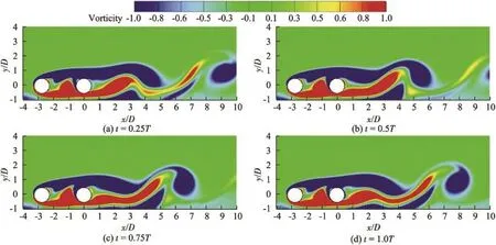
Fig.3.Evolution of vortex feld for one-wake mode whenG/D=1.00 andL/D=2.75.

Fig.4.Evolution of vortex feld for two-wake mode whenG/D=1.0 andL/D=3.0.
The fow structure of the two-wake mode is completely different from that of the one-wake mode because the vortices are shed from both sides of the two circular cylinders. Compared with the one-wake mode,the vortex dimension in the wake of the downstream cylinder for the two-wake mode is reduced.Strong interference between the two wakes can be observed.The vortex shedding from the upstream cylinder is rolled into the near wake of the downstream cylinder.It seems that the vortices are shed from the upstream and downstream circular cylinders at the same frequency,but with a phase lag. The reason for this is that the vortices are shed from the upstream cylinder and downstream cylinder at the same time but with a positive vortex for the upstream cylinder and a negative vortex for the downstream cylinder,as shown in Figs.4(c)and(d). As in the one-wake mode,the shear layer,which develops on the plane wall,has little infuence on the near wakes of the two cylinders.
4.1.4.Identifcation of vortex shedding mode
The vortex shedding modes in the three wake modes were identifed according to the computations in this study,and are shown in Table 3.It can be seen from Table 3 that,forG/D= 0.50,the no-shedding mode is observed whenL/D≤ 3.25,whilethetwo-wakemodeoccurs when 3.50≤L/D≤4.00.Hence,there must exist a critical distance ratioLcr/Dranging from 3.25 to 3.5,which determines the transition between the two vortex shedding modes.Table 3 also show that change in the vortex shedding mode from the one-wake mode to the two-wake mode can be observed whenG/D!0.75,implying the existence of the critical distance ratio.However,no critical distance ratio can be obtained whenG/D=0.25 since only the no-shedding mode was observed over the whole span ofL/Din this study.
It should be noted that there is a one-wake vortex shedding mode whenG/D=2.00 andL/D=3.00,but a two-wake mode whenG/D=2.00 andL/D=2.75 and 3.25.It can be inferred that the fuid fows for 2.75≤L/D≤3.25 are located at the transition between the one-wake mode and the two-wake mode.In the case ofG/D=2.00 and 2.75≤L/D≤3.25, the gap between the plane wall and two cylinders is so large that the shear layer generated on the plane wall has limited infuence on the near wakes of the two cylinders.However,the center-to-center distance between the two cylinders is not large enough,resulting in a high degree of fow interaction in the gap between the two cylinders.Such strong interaction makes the fuid structure more complex.Thus,a transitionbetween the one-wake mode and the two-wake mode may occur.

Table 3 Vortex shedding modes for different values ofL/DandG/DatRe=200
4.2.Hydrodynamic force coeffcients of cylinders
The numerical simulations in this study show a close correlation between the hydrodynamic force coeffcients and vortex shedding modes.This will be demonstrated by the time history of hydrodynamic force coeffcients and the statistics of hydrodynamic force coeffcients.
4.2.1.Time series of drag and lift coeffcients
Fig.5 shows the time history of drag and lift coeffcients of the upstream and downstream cylinders for the three cases ofG/D=0.25 andL/D=2.75,G/D=0.75 andL/D=2.75,andG/D=2.00 andL/D=2.75,which correspond to the previously mentioned no-shedding mode,one-wake mode,and twowake mode,respectively.In Fig.5,CDuandCLurepresent the drag and lift coeffcients of the upstream cylinder,respectively, andCDdandCLdare the drag and lift coeffcients of the downstream cylinder,respectively.
It can be seen from Figs.5(a)and(b)that the drag and lift coeffcients of each cylinder attain a constant value over time. The initial oscillations of hydrodynamic fuid coeffcients, resulting from the disturbance at the beginning of numerical computations,are quickly damped out.This means that the noshedding mode is dominated by the absolute fow stability, mainly attributed to the small gap between the cylinders and the plane wall.
Oscillations of drag and lift coeffcients of the downstream cylinder can be observed when the one-wake mode appears,as shown in Fig.5(d),whereas Fig.5(c)demonstrates that the oscillationsofthedragandliftcoeffcientsoftheupstreamcylinder are rather limited.It should be noted that the drag coeffcient of theupstreamcylinderismuchlargerthanthatofthedownstream cylinder.It can also be found that the frequency of the drag coeffcientofthedownstreamcylinderisnottwicethefrequencyof lift coeffcient but shares the same value,in contrast to the usual observation for an isolated cylinder in an infnite fow domain. An anti-phase variation with time is identifed between the lift and drag coeffcients for the downstream cylinder.
For the two-wake mode,as shown in Figs.5(e)and(f),the amplitudes of both the fuctuating drag and lift coeffcients increase drastically,compared with their counterparts in Figs.5(a)to 5(d).This is mainly due to the appearance of vortex shedding from both cylinders and the interference between them.It is confrmed thatCLuandCLdhave the same oscillating frequency but opposite phases,which is consistent with the observations shown in Fig.4.However,this is not valid for the drag coeffcients of the two cylinders.It seems that the drag coeffcient of the upstream cylinder involves multiple frequency components.Generally speaking,thefuctuations of drag and lift coeffcients of each cylinder and the relationships between them are much more complex than those of an isolated cylinder in free stream fows.

Fig.5.Time history of drag and lift coeffcients of upstream and downstream cylinders for different vortex shedding modes atRe=200.
4.2.2.Mean hydrodynamic force coeffcients of cylinders
The mean drag and lift coeffcients of two cylinders are presented in Fig.6.It can be seen that positive mean drag coeffcients of the upstream cylinderCDuare observed for all combinations ofG/DandL/Dconsidered in this study.At the smallest value ofG/D=0.25,increases with the increase ofL/D,and its growth rate in the range of 1.00≤L/D≤1.50 is larger than that in the range ofL/D!1.75.ForG/D=0.50, a gradually growing tendency can be observed forwhenL/D≤1.50,and then a slightly decreasing trend forwhen 1.50<L/D≤3.25.When the vortex shedding mode changes from the no-shedding mode to the two-wake mode,a minor increase ofwithL/Dcan be observed.Then,holds almost a constant whenL/D!3.50.When the one-wake mode occurs,as shown in Table 3,the values ofare almost constant with a constantL/Dvalue whenG/D=1.00,1.50, and 2.00,and they decrease slightly with the increase ofL/D. For the two-wake mode,changes little with the increase ofL/Dfor a constantG/Dvalue,indicating that theL/Dvalue has a limited effect on the mean drag coeffcient of the upstream cylinder in the two-wake mode.
As far as the mean lift coeffcient of the upstream cylinderis concerned,Fig.6(b)demonstrates the signifcant infuence of the plane wall onAs shown in Fig.6(b),the values ofwhen 0.50≤G/D≤1.00 may be either positive or negative,while overall positive values ofare observed whenG/D=0.25,1.50,and 2.00.The mean lift coeffcient of the upstream cylinderis dependent on the fow speed beneath the upstream cylinder,which is not only directly related to the gap ratioG/D,but also partially related to the distance ratioL/D.When the gap ratioG/Dis small enough and the two cylinders approach one another,the strong blockage effect leads to a low fow speed beneath the upstream cylinder and high pressure along the lower side of the upstream cylinder,which accounts for positive mean lift forces of the upstream cylinder.Otherwise,as the gap ratioG/Dincreases gradually,the fow speed increases in the gap between the upstream cylinder and plane wall,causing the pressure along the lower side of the upstream cylinder to be smaller than that along the upper side.Therefore,negative mean lift coeffcients are observed.Moreover,it can be seen from Fig.6(b)that the distance ratio has a rather limited effect on the mean lift coeffcient whenL/D!3.25 for all values ofG/D.It can also be seen in Fig.6(b)that the mean lift coeffcient of the upstream cylinder whenG/D=0.25 is much larger than those whenG/D>0.25.The reason for this is that the very small gap between the upstream cylinder and the plane wall causes the pressure below the cylinder to be larger than that above it,and the large pressure difference further induces a large positive value of the mean lift coeffcient of the upstream cylinder.

Fig.6.Time-averaged hydrodynamic force coeffcients of upstream and downstream cylinders.
Fig.6(c)displays the mean drag coeffcients of the downstream cylinder with respect toG/DandL/D.It can be seen from Fig.6(c)thatis positive for all values ofL/Dwhendecreases slowly with the increase ofL/DwhenG/D=0.25,whereas it increases slightly withL/DwhenG/D=0.50.For the one-wake mode,increases generally withL/D,negative mean drag coeffcients can be found,and the bandwidth ofL/Dfor negative mean drag coeffcients increases withG/D.The appearance of negative mean drag coeffcients of the downstream cylinder is mainly induced by the shielding effect from the upstream cylinder.This is confrmed by numerical results showing that an extremely low pressure distribution,together with a well-developed stable vortex structure,is observed between the two cylinders. Comparison of Figs.6(a)and(c)shows that the switch in the vortex shedding mode,as shown in Table 3,is associated with the jumps of mean drag coeffcients of both cylinders.In general,is smaller thanfor the same combination ofG/DandL/D.The variation ofwith the gap ratioG/Dis not same as that ofThis is because the hydrodynamic force coeffcients of the downstream cylinder are mainly affected by the vortices behind the upstream cylinder.
Fig.6(d)presents the mean lift coeffcient for the downstream cylinder.It can be seen from Fig.6(d)that,for the noshedding mode,decreases with the increase ofL/DwhenG/D= 0.25,while it varies slightly withL/DwhenG/D=0.50.For the one-wake mode,it is observed thatincreases with the increase ofL/D.However,decreases with the increase ofL/Dfor the two-wake mode.It can also be found thatthe maximalmean liftcoeffcientsofthe downstream cylinder for variousG/Dvalues occur when theL/Dvalues are very close to the critical distance ratiosLcr/D.The positive mean lift coeffcient of the downstream cylinder is mainly attributed to the boundary layer developing along the plane wall,which decreases the fow fux in the gap between the cylinder and plane wall and increases the pressure at the lower side of the downstream cylinder.This is evident in the no-shedding mode.In addition,thevortex shedding from the downstream cylinder in the one-wake mode becomes asymmetrical due to the existence of the plane wall boundary layer, which accounts for the positive mean lift coeffcient.The vortex shedding from the upstream cylinder in the two-wake mode can further strengthen the asymmetrical vortex shedding,giving rise to the maximal lift coeffcient in Fig.6(d).
4.2.3.Root mean square values of hydrodynamic force
coeffcients
The RMS values of drag and lift coeffcients of both cylinders are shown in Fig.7.Figs.7(a)and(b)show that bothandincrease abruptly from very small values as the vortex shedding mode changes.For the two-wake mode,it is observed thatanddecrease with the increase of theL/Dvalue for a constantG/Dvalue.However,very small values ofandcan be seen when the one-wake mode occurs.WhenG/D=0.25,the values of bothandare zero for all theL/Dvalues.This is attributed to the lack of vortex shedding behind the two cylinders.

Fig.7.RMS values of hydrodynamic force coeffcients of upstream and downstream cylinders.
Figs.7(c)and(d)present the RMS values of drag and lift coeffcients for the downstream cylinder.The change in the vortex shedding mode again induces dramatic increases of hydrodynamic force coeffcient fuctuations.We suggest that the vortex shedding from the upstream cylinder has a more signifcant infuence on the RMS values of hydrodynamic force coeffcients of the downstream cylinder than on those of the upstream cylinder.This is further confrmed in Fig.7(d),in which larger increments of RMS of the lift coeffcient from the one-wake mode to the two-wake mode are shown with respect to Fig.7(b).Comparison between Fig.7(b)and Fig.7(d)indicates that the increase ofG/Din the two-wake mode has a greater infuence onthan
It is also seen in Fig.7 that the RMS values of the drag and lift coeffcients are both very small for the one-wake mode. Though the mean lift coeffcients of both cylinders are smaller than the mean drag coeffcients for the same combination ofL/DandG/D(Fig.6)in the two-wake mode,the RMS values of the drag and lift coeffcients of the downstream cylinder are much greater than the counterparts of the upstream cylinder, respectively,whenL/Dis larger thanLcr/D.The main reason for this phenomenon is that the magnitude of the shedding vortices behind the downstream cylinder is larger than that behind the upstream cylinder in the two-wake mode.When the two-wake mode occurs,the RMS values of the lift coeffcients of upstream and downstream cylinders increase withG/DwhenG/D≤1.50 for a constant value ofL/D,and the RMS values of the lift coeffcient of two cylinders are similar for the same combination ofG/DandL/DwhenG/D=1.50 and 2.00. However,the RMS values of the drag coeffcients of both cylinders do not show such tendencies.
Fig.8 shows the Strouhal number for the downstream cylinder(Std)with different values ofG/DandL/D.It can be seen from Fig.8 that the value ofStdis zero in the no-shedding mode.WhenG/D=0.50,Stdincreases with the increase of theL/Dvalueasthetwo-wakemodeoccurs.WhenG/D=0.75,Stddecreases with the increase ofL/Dfor the one-wake mode,and increases withL/Dfor the two-wake mode.WhenG/D>1.00,the values ofStdare close to one another for the same value ofL/Dand different values ofG/D, implying that theG/Dvalue has a limited effect onStd. However,this is not true for the cases ofG/D=2.00 andL/D=2.50,andG/D=2.00 andL/D=3.00,which correspond to the boundaries of different vortex shedding modes,as shown in Table 3.

Fig.8.Strouhal numberStdfor downstream cylinder with different values ofL/DandG/DatRe=200.
5.Conclusions
Viscous fow past twin near-wall circular cylinders in a tandem arrangement was investigated numerically at a low Reynolds number. Calculations were carried out forG/D=0.25,0.50,0.75,1.00,1.50,and 2.00,andL/Dranging from 1.0 to 4.0 with an interval of 0.25.The Reynolds number was kept constant and equal to 200 for all of the computations. The infuences ofG/DandL/Dvalues on hydrodynamic force coeffcients,vortex shedding modes,and Strouhal numbers were examined.The major results can be summarized as follows:
(1)There is no vortex shedding from the cylinders for very small values ofG/D.In this study,vortex shedding was not observed in the cases ofG/D=0.25 for all values ofL/D,and the cases ofG/D=0.50 andL/D≤3.25.
(2)WhenG/D=0.25,vortex shedding can be completely suppressed for all values ofL/D.WhenG/D!0.50,there is a critical distance ratioLcr/D.IfL/D>Lcr/D,it can be found that the vortices are shed from both the upstream and downstream cylinders,a situation defned as the two-wake mode in this study.However,whenL/D≤Lcr/D,a no-shedding mode is observed whenG/D=0.50,and the vortex is shed only from the downstream cylinder whenG/D!0.75.
(3)The lift coeffcients of the downstream and upstream cylinders oscillate at the same frequency in the two-wake mode,implying that the Strouhal number is the same for both cylinders.The Strouhal number for the downstream cylinder is zero in the no-shedding mode,since vortex shedding is totally suppressed.It is also observed that the values ofStdare close to one another for the same value ofL/Dand different values ofG/DwhenG/D>1.00,except for the cases ofG/D=2.00 andL/D=2.50,andG/D=2.00 andL/D=3.00.
(4)At a very small value ofG/D,such asG/D=0.25,the vortex shedding is completely suppressed,and the mean drag coeffcients for both cylinders change smoothly with the increase of theL/Dvalue.WhenG/D!0.50,the root mean square values of drag and lift coeffcients of both cylinders increase abruptly when the vortex shedding mode is changed.
(5)When the two-wake mode occurs,the mean drag coeffcient of the upstream cylinder increases withG/DwhenG/D≤1.50,while the mean drag coeffcients are similar to one another whenG/D=1.50 and 2.00 for the same values ofL/D.The mean drag coeffcient of the downstream cylinder is negative for small values ofL/Dand positive for large values ofL/DwhenG/D>0.50,and the bandwidth ofL/Dfor the negative mean drag coeffcient of the downstream cylinder increases withG/D.
(6)The mean drag coeffcient of the upstream cylinder is larger than that of the downstream cylinder for the same combination ofG/DandL/D.However,the RMS values of drag and lift coeffcients of the downstream cylinder are much larger than the counterparts of the upstream cylinder in the two-wake mode.
Angrilli,F.,Bergamaschi,S.,Cossalter,V.,1982.Investigation of wall induced modifcations to vortex shedding from a circular cylinder.J.Fluids Eng. 104(4),518-552.http://dx.doi.org/10.1115/1.3241896.
Bearman,P.W.,Wadcock,A.J.,1973.The interaction between a pair of circular cylinders normal to a stream.J.Fluid Mech.61(3),499-511.http:// dx.doi.org/10.1017/S0022112073000832.
Bearman,P.W.,Zdravkovich,M.M.,1978.Flow around a circular cylinder near a plane boundary.J.Fluid Mech.89(1),33-47.http://dx.doi.org/10. 1017/S002211207800244X.
Cheng,M.,Tsuei,H.E.,Chow,K.L.,1994.Experimental study on fow interference phenomena of cylinder/cylinder and cylinder/plane arrangements.In:Flow-induced Vibration.ASME,New York,pp.173-184.
Grass,A.J.,Raven,P.W.J.,Stuart,R.J.,Bray,J.A.,1984.The infuence of boundary layer velocity gradients and bed proximity on vortex shedding from free spanning pipelines.J.Energy Resour.Technol.106(1),70-78. http://doi.org/10.1115/1.3231028.
Ishigai,S.,Nishikawa,E.,Nishimura,K.,Cho,K.,1972.Experimental study on structure of gas fow in tube banks with tube axes normal to fow,Part 1: Karman vortex fow from two tubes at various spacings.Bull.JSME 15(86),949-956.http://doi.org/10.1299/jsme1958.15.949.
Jester,W.,Kallinderis,Y.,2003.Numerical study of incompressible fow about fxed cylinder pairs.J.Fluids Struct.17(4),561-577.http://dx.doi.org/10. 1016/S0889-9746(02)00149-4.
Jiang,C.B.,Kawahara,M.,1993.A three-step fnite element method for unsteady incompressible fows.Comput.Mech.11(5-6),355-370.http://dx. doi.org/10.1007/BF00350093.
Kim,H.J.,Durbin,P.A.,1988.Investigation of the fow between a pair of circular cylinders in the fopping regime.J.Fluid Mech.196,431-448. http://dx.doi.org/10.1017/S0022112088002769.
King,R.,Johns,D.J.,1976.Wake interaction experiments with two fexible circular cylinders in fowing water.J.Sound Vib.45(2),259-283.http:// dx.doi.org/10.1016/0022-460X(76)90601-5.
Kostiˊc,ˇZ.G.,Oka,S.N.,1972.Fluid fow and heat transfer with two cylinders in cross fow.Int.J.Heat Mass Transf.15(2),279-299.http://dx.doi.org/ 10.1016/0017-9310(72)90075-0.
Lei,C.,Cheng,L.,Kavanagh,K.,1999.Re-examination of the effect of a plane boundary on force and vortex shedding of a circular cylinder.J. Wind Eng.Industrial Aerodynamics 80(3),263-286.http://dx.doi.org/10. 1016/S0167-6105(98)00204-9.
Lei,C.,Cheng,L.,Armfeld,S.W.,Kavanagh,K.,2000.Vortex shedding suppression for fow over a circular cylinder near a plane boundary.Ocean. Eng. 27(10), 1109-1127. http://dx.doi.org/10.1016/S0029-8018(99) 00033-5.
Meneghini,J.R.,Saltara,F.,Siqueira,C.L.R.,Ferrari Jr.,J.A.,2001.Numerical simulation of fow interference between two circular cylinders in tandem and side-by-side arrangements.J.Fluids Struct.15(2),327-350.http://dx. doi.org/10.1006/jfs.2000.0343.
Mittal,S.,Kumar,V.,Raghuvanshi,A.,1997.Unsteady incompressible fows past two cylinders in tandem and staggered arrangements.Int.J.Numer. Methods Fluids 25(11),1315-1344.http://dx.doi.org/10.1002/(SICI)1097-0363(19971215)25:11%3C1315::AID-FLD617%3E3.0.CO;2-P.
Price,S.J.,Sumner,D.,Smith,J.G.,Leong,K.,Paigdoussis,M.P.,2002.Flow visualization around a circular cylinder near to a plane wall.J.Fluids Struct.16(2),175-191.http://dx.doi.org/10.1006/jfs.2001.0413.
Tanida,Y.,Okajima,A.,Watanabe,Y.,1973.Stability of a circular cylinder oscillating in uniform fow or in a wake.J.Fluid Mech.61(4),769-784. http://dx.doi.org/10.1017/S0022112073000935.
Williamson,C.H.K.,1985.Evolution of a single wake behind a pair of bluff bodies. J. Fluid Mech. 159, 1-18. http://dx.doi.org/10.1017/ S002211208500307X.
Williamson,C.H.K.,1988.The existence of two stages in the transition to three dimensionality of a cylinder wake.Phys.Fluids 31(11),3165-3168. http://dx.doi.org/10.1063/1.866925.
Williamson,C.H.K.,1989.Oblique and parallel modes of vortex shedding in the wake of a circular cylinder at low Reynolds numbers.J.Fluid Mech. 206,579-627.http://dx.doi.org/10.1017/S0022112089002429.
Zdravkovich,M.M.,1977.Review of fow interference between two circular cylinders in various arrangements.J.Fluids Eng.99(4),618-633.http:// dx.doi.org/10.1115/1.3448871.
Zdravkovich,M.M.,1987.The effects of interference between circular cylinders in cross fow.J.Fluids Struct.1(2),239-261.http://dx.doi.org/10. 1016/S0889-9746(87)90355-0.
Received 30 August 2014;accepted 9 June 2015
Available online 11 August 2015
This work was supported by the National Natural Science Foundation of China(Grants No.51409035,51279029,and 51490673)and the Open Fund from the Key Laboratory of Harbor,Waterway and Sedimentation Engineering of Ministry of Communications,Nanjing Hydraulic Research Institute.
*Corresponding author.
E-mail address:lulin@dlut.edu.cn(Lin Lu).
Peer review under responsibility of Hohai University.
http://dx.doi.org/10.1016/j.wse.2015.06.002
1674-2370/©2015 Hohai University.Production and hosting by Elsevier B.V.This is an open access article under the CC BY-NC-ND license(http:// creativecommons.org/licenses/by-nc-nd/4.0/).
 Water Science and Engineering2015年4期
- Water Science and Engineering的其它文章
- Observation and modeling of tide-and wind-induced surface currents in Galway Bay
- Deposited sediment settlement and consolidation mechanisms
- Seepage and stress analysis of anti-seepage structures constructed with different concrete materials in an RCC gravity dam
- Analysis of effect of nicotine on microbial community structure in sediment using PCR-DGGE fngerprinting
- Impacts of water quality variation and rainfall runoff on Jinpen Reservoir, in Northwest China
- Effects of temporal variability on HBV model calibration