Error modeling of 3-RSR parallel robot based on D-H transformation matrix
LI Rui-qin,YANG Bin
(School of Mechanical and Power Engineering,North University of China,Taiyuan 030051,China)
0 Introduction
Parallel robot is an important branch of robot mechanisms.Research on parallel robot has drawn the attention of many scholars.In recent years,limited-DOF (degree of freedom) parallel robot has become a new research focus.Compared with 6-DOF parallel robot,limited-DOF parallel robot has the advantages of simple structure,low cost,large workspace,etc.Here,3-DOF parallel robot is a typical limited-DOF parallel robot and has a broader application prospect in the industrial production and other fields.
At present,research on 3-DOF parallel robot is mainly concentrated on various kinematic and dynamic performance indexes.Research on accuracy,one of the most important performance indexes of parallel robot,is insufficient.
Errors of a parallel robot include principle error,manufacturing error,using error,measuring error,etc.The main source of errors of parallel robot mechanism is determined by manufacturing error,i.e.machining error of main components and parts,assembly error[1].How to establish a proper error model is the key to accuracy research.Now,research on accuracy of parallel mechanisms includes Denavit-Hartenberg (D-H) transformation matrix and space vector chain method.
D-H transformation matrix is a method which is widely used in error modeling.The position relationship between the links in parallel robot can be described by D-H matrix.The parameters in D-H matrix are the error sources which lead to the errors of the end effector.WANG et al[2]established the error model of Delta platform with D-H coordinate; SHAN et al[3]established error model of Stewart parallel machine tool with D-H matrix differential method.
Some scholars have studied the accuracy of the parallel mechanism using vector algebra method.ZHU[4]described the possible error range of moving platform of 6-SPS parallel mechanism using the planar and spatial error probability analysis,but the specific influence degree of every structure error on the output position and orientation error is not clear.Ropponen et al[5]had derived the calculation model of the position and orientation error of the parallel robots with a vector chain and vector differential method.ZENG et al[1]had an in-depth study on accuracy problem of 3-RRR parallel computer numerical control (CNC) revolving platform by using space vector chain analysis method.LI et al[6]established a position and orientation error model of 3-RRR anthropomorphic shoulder with the differential method.ZHANG et al[7]discussed the pose error of planar mechanism with joint clearance by means of the combined theories of error analysis,optimization and virtual displacement and proposed a calculation method for the pose error of planar mechanism.LIU[8]addressed the dimensional optimization of two types of tool heads with 3-PVPHS and 3-PVRS parallel kinematics by considering their orientation capability and positioning accuracy.They investigated the tilt angle of the spherical joint,the orientation capability,and the error of one point from the mobile platform caused by input errors.
As we know,3-RSR parallel robot is a kind of 3-DOF parallel robot which can be widely used in some high accuracy workplaces,such as radar antenna support,surgical robot,etc.References for studying on this kind of mechanism are relatively insufficient.LIU et al[9]studied dynamic simulation of 3-RSR flexible parallel robot.They established the virtual prototype of a 3-RSR parallel robot with flexible links on the basis of the finite element software SAMCEF,and analyzed the displacement,acceleration and equivalent stress of the 3-RSR flexible parallel robot.
The paper takes 3-RSR parallel robot as a research object and studies its error modeling.
1 Configuration of 3-RSR parallel robot and coordinate systems
The configuration of 3-RSR parallel robot is shown in Fig.1.
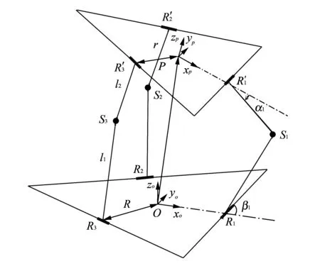
Fig.1 Equivalent structure of 3-RSR parallel robot
As shown in Fig.1,3-RSR parallel robot is a symmetrical structure.Both upper platform (the moving platform) and lower platform (the base) are similar equilateral triangles.The base connects with the moving platform by three same limbs.Three driving links are connected with the base by revolute pairs.Three passive links are connected with the moving platform also by revolute pairs.Three spherical pairs connect the driving links and the passive links.
The base coordinate systemO-xoyozois connected with the base.PointOis located at the geometric centre of the base.xo-axis and vectorOR1are collinear and point toR1;zo-axis is perpendicular to the base plane; andyo-axis is determined according to the right hand rule.


2 D-H model of 3-RSR parallel robot
2.1 Equivalent structure model of limbs
Because three limbs of 3-RSR parallel robot are all identical,the following research selects any one limb as research object and establishes the D-H matrix without loss of generality.
Each limb includes two revolute pairs and one spherical pair.The spherical pair can be equivalent to three revolute pairs.The equivalent structure of one limb is shown in Fig.2.The transformed equivalent structure facilitates the establishment of D-H matrix,and the link coordinate systems inith limb are established,as shown in Fig.2.
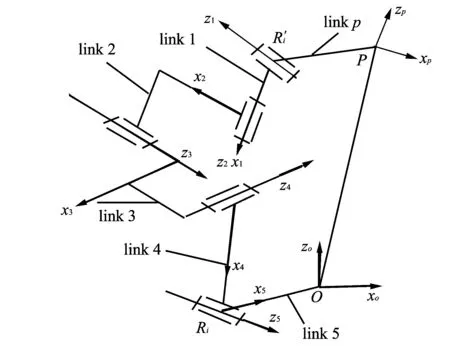
Fig.2 An equivalent model of ith limb
The relation betweenP-xpzpsystem and 1 system is as follows:
Firstly,P-xpzpsystem movesrcosφPiandrsinφPialongx-direction andy-direction,respectively.
Then,P-xpzpsystem rotates anglesφPi,γPiandλPiaroundzp-direction,yp-direction andxp-direction,respectively.

Because two links are connected by using spherical pair that can be equivalent to three revolute pairs,it is convenient to find the relationship between two links by means of D-H matrix.
In a limb,there are four D-H parameters associated with linki.As shown in Fig.3,parameter definitions are as follows.
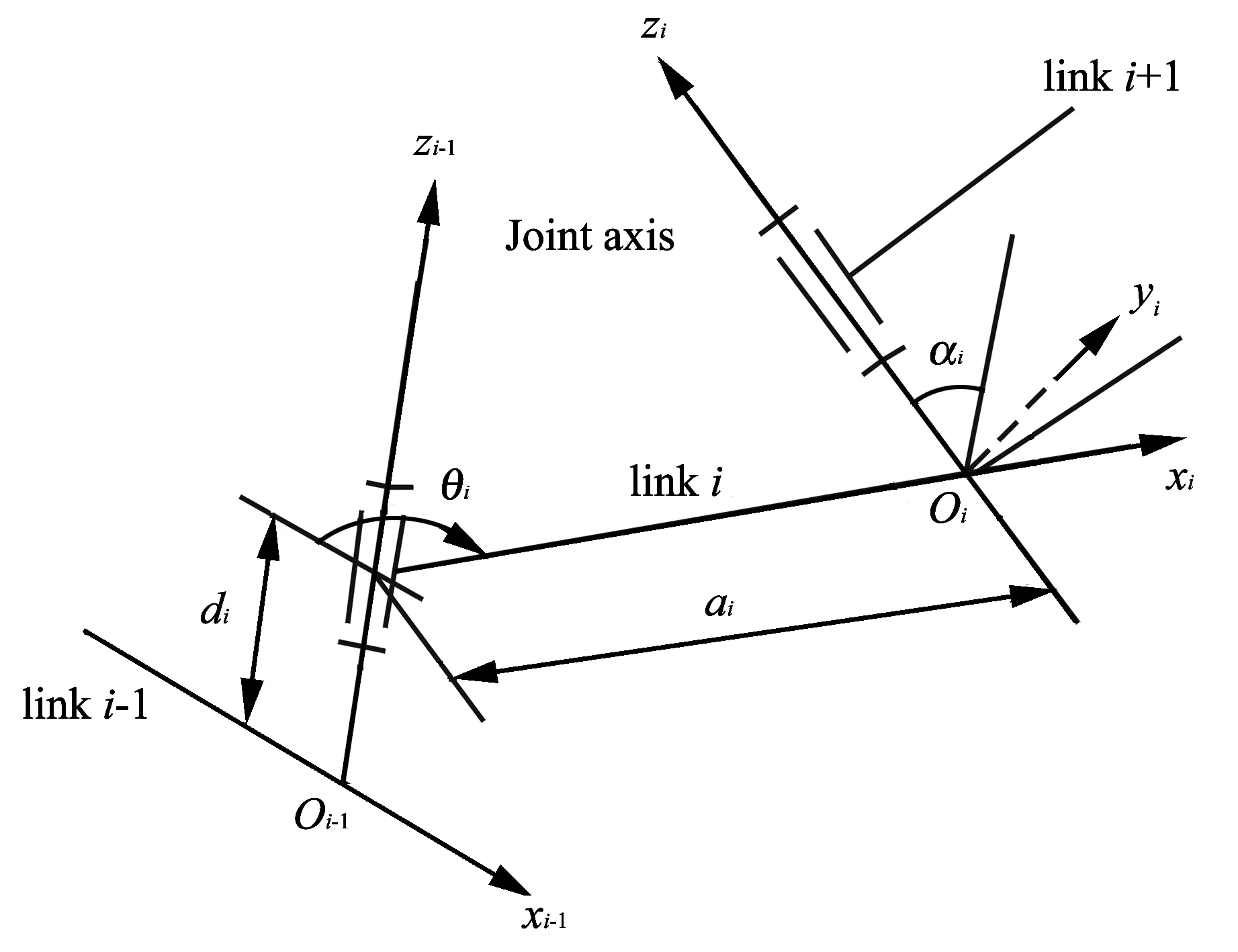
Fig.3 Parameter definitions between two adjacent links
Twist angleαi,the angle of joint axisziof linksirelative to axeszi-1.
Link distancedi,the distance of two adjacent linkiandi-1 along axeszi-1fromxi-1toxi.
Link lengthai,the length of common perpendicular line between two adjacent joint axisziandzi-1
in linki.
Rotating angleθi,the angle of linkirotating around axiszi-1.
Because all joints are rotating joints in equivalent limb,link lengthai,twist angleαiand link distancediare all constant,called structure parameters or geometric parameters.Rotating angleθiis variable,called joint variable.
Then,the position and orientation of linkirelative to linki-1 is
(1)
wherecexpresses cos;sexpresses sin.The below is the same.
Eq.(1) expresses a transformation matrix of coordinate systemirelative to coordinate systemi-1,called D-H transformation matrix.
2.2 Position and orientation of 3-RSR para-llel robot
D-H transformation matrix can be used to describe the position and orientation equation of 3-RSR parallel mechanism.
Defining the position vector of the reference pointPof the moving platform in the base coordinate systemO-xoyozoas
PO=(xpoypozpo)T.
Thex-y-zEuler angle that moving platform relative to the base is
θ=(θxθyθz)T,
wherexpo,ypo,zpo,θx,θy,θzare called theoretical position and orientation parameters of 3-RSR parallel robot.
Taking one limb for example,the position and orientation equation of 3-RSR parallel robot can be described as
P=T1T2T3T4U5T6,
(2)
wherePis position and orientation equation of the moving platform andTiis transformation matrix ofisystem relative toi-1 system.
Position and orientation matrixPof the moving platform in Eq.(2) can also be described by

(3)
whereRis orientation matrix of the moving platform; trans ( ) expresses translation transformation; rot ( ) expresses rotation transformation.
The D-H matrix ofisystem relative toi-1 system in the limb can be described as follows.
The D-H transformation matrix of 1 system relative toP-xpzpsystem is

(4)

(5)
The D-H transformation matrix of 5 system relative toO-xozosystem is as follows

(6)

(7)
Finally,D-H transformation matrix of the moving platform relative to the base of 3-RSR parallel robot can be easily described,i.e.Eq.(2) can be rewritten as
(8)
We can see that there are all six D-H transformation matrices,where two of them are described as above.There remain four D-H transformation matrices.Because the five rotational joints are perpendicular to each other,αi=90° (i=2,3,4,5).The parameters of these four D-H tranformation matrices are shown in Table 1.

Table 1 Parameters of D-H tranformation matrix
In Table 1,θiexpresses the rotating angle between link systemiand link systemi-1.
Table 1 reflects the position relationship among these linkages in 3-RSR parallel robot.If the D-H transormation matrix is established between two adjacent links by using the parameters in Table 1,and then these parameters are taken into Eq.(8),D-H transormation matrix that the moving platform relative to the base can be got easily.Finally,its concrete representation can be obtained by using Matlab software.
The parameters of D-H tranformation matrix are the sources of the error of the robot.It is inevitable to produce geometric errors in manufacturing and assembly process.Therefore,error modeling has much significance to the research on accuracy problem.
3 Error model of 3-RSR parallel robot
3.1 Differential translation and rotation transformation
According to the matrix differential method,the differential form of position and oriention matrixPcan be described as
dP=Δ·P,
(9)
whereΔexpresses differential moving matrix of moving platform coordinate systemPrelative to the base coordinate systemO.
Δ=trans(dx,dy,dz)rot(k,dθ)-I.
(10)
According to

then
(11)
wherekx,kyandkzare direction cosine of spatial arbitrary axisK.
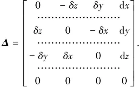
Thus,Δcan be simplified as
(12)
Letkxdθ=δx,kydθ=δy,kzdθ=δz,then Eq.(12) can be rewritten as
(13)
The differential form of D-H transformation matrixTican be described as[10]
dTi=TiΔi,
(14)
dTi=ΔTi,
(15)
whereΔiexpresses the differential moving matrix of linkiwith respect to the coordinate system itself.
From Eqs.(14) and (15),we can get
(16)
The expression reflects differential relationship among different coordinate systems.
Suppose
(17)
Then
(18)
wheren,o,aandpare the unit column vectors of transformation matrixTi,andn,oandaare pairwise orthogonal.
Substituting Eqs.(13),(17) and (18) into Eq.(16),it can be got
(19)
where dx,dyand dzexpress displacement errors of the moving platform;δx,δyandδzexpress rotating angle errors of the moving platform.
3.2 Error modeling of position and orientation of 3-RSR parallel robot
Error modeling of position and orientation of parallel mechanism needs starting from its limbs.Three limbs of 3-RSR parallel robot have identical structure and dimensions.Hence,we only need error modeling aiming at one of three limbs.
Every limb belongs to series mechanism,and the error of the platform is accumulation error from original errors dθi,dai,ddiand dαiof every joint.
Differentiating Eq.(2),then it can be got
(20)
Substituting Eq.(14) into Eq.(20),then it can be got
(21)
Transforming the form of Eq.(9) as
Δ=P-1dP.
(22)
Substituting Eqs.(8),Eq.(19) and (21) into Eq.(22),then it can be got

(23)
Therefore,when knowing original errors of the robot,we can conveniently solve the overall error of the platform according to the above Eq.(23).
This method has the advantage of the accuracy of solution.The overall error of the mechanism can also be conveniently solved by using related mathematics software.
The following will solve the overall error of 3-RSR parallel robot by using this method through case study.
4 Case study
The simulation model is established,as shown in Fig.4.
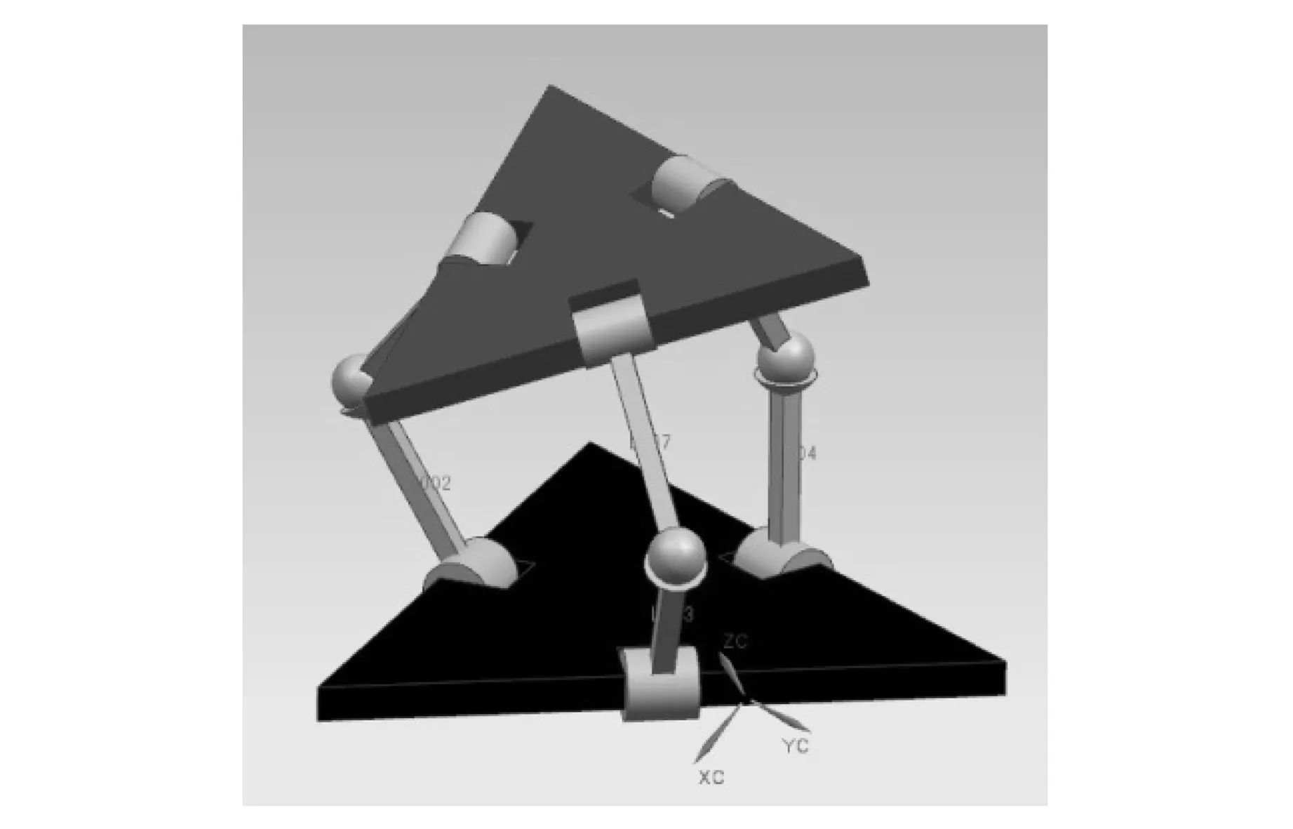
Fig.4 Simulation model
3-RSR parallel robot can be applied in the surgical operation.Its motion space is not large.Its structure is symmetrical.
Suppose the length of six links in three limbs are all 300 mm,l1=l2=300 mm.The distance between the center of the platform and the base and its revolute pair are all 250 mm.Let the orientation of initial position be
φPi=φOi=0°,
γPi=γOi=0°,
λPi=λOi=0°
(i=1,2,3).
Considering the actual running condition of 3-RSR,the range of rotating angles between links are supposed to be
θ2∈[50°,120°],
θ3,θ4,θ5∈[40°,120°].
Considering the accuracy requirement of surgical operation,machining error is supposed to be of higher grade than general machining error.The tolerance range of the length of links is [-IT7,IT7].The geometric angle error is [-0.6°,0.6°].
SHAN[3]has proved that that by using error modeling of arbitrary one of limbs is very close to the calculating result of the moving platform error in parallel robot.The overall error of 3-RSR parallel robot can be calculated by using any one of three limbs.Then,simulation results can be obtained by substituting original data into the above equations by means of Matlab software.
Because of symmetrical structure of 3-RSR parallel robot,the motions of the rotating angles between adjacent links have identical influence on the moving platform error.
In the actual simulation process,if the rotating angleθ2is selected as a variable,there is no loss of generality,and the other joint variables are supposed to be constant.Suppose all the rotating anglesθi=60° (i=3,4,5) except the angleθ2,the influence rules for motion error of 3-RSR parallel robot are carefully observed when single angle rotates.The results are shown in Fig.5.
5 Discussion for calculation results
In Fig.5,the variation range is one period in order to facilitate to observe the complete error rule.
From Fig.5,the variation rules of the position and orientation of 3-RSR parallel robot with rotating angles can be obviously observed.
In Fig.5(a),the displacement error alongzoaxis direction is the largest and linearly increases along with the angle changing.Therefore,we should pay special attention to the error compensation alongxoaxis direction.
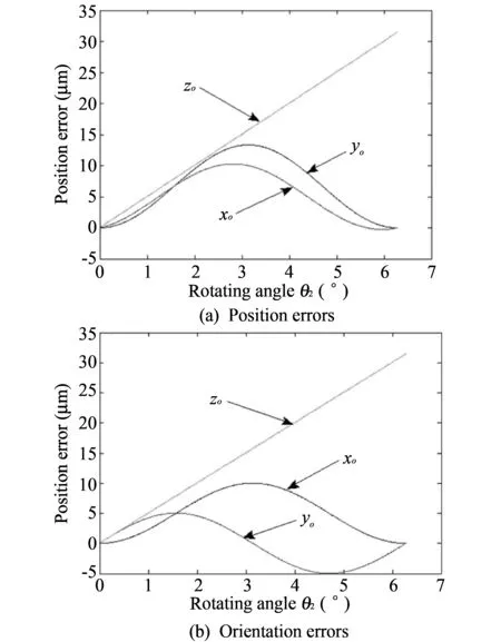
Fig.5 Position errors and orientation errors of 3-RSR parallel robot
The displacement errors alongxoaxis direction andyoaxis direction have a roughly sine curve.The maximum value of the displacement error alongxoaxis direction andyoaxis direction appears atθ2=π.Therefore in the actual running process,we should avoid the circumstance ofθ2=πas far as possible.


6 Conclusion
The paper established matrix relation model from the moving platform to the base of 3-RSR parallel robot by using D-H matrix.The error modeling of 3-RSR parallel robot is obtained by differentiating the established D-H matrix and deformation by using matrix differential method.By means of Matlab software,the influence rules of the original error of one link’s rotating angle for the position and orientation error of the moving platform can be observed clearly.The results provide a basis for further error analysis and error compensation.
[1] ZENG Xian-jing,HUANG Tian,ZENG Zi-ping.Accuracy analysis of the 3-RRR NC swivel worktable.Chinese journal of mechanical engineering,2001,37(11): 42-45.
[2] Wang J,Masory O.On the accuracy of a Stewart platform-Part I the effect of manufacturing tolerance.In Proceeding of IEEE International Conference on Robotics and Automation,1993,1: 114-120.
[3] SHAN Peng,XIE Liyang,TIAN Wanlu,et al.Modeling of position and pose Error of Stewart machine tool based on D-H transforming matrix.Journal of mechanical engineering,2010,46(17): 186-190.
[4] ZHU Jian-min,Ting Kwun-Lon.Uncertainty analysis of planar and spatial robots with joint clearances.Mechanism and Machine Theory,2000,35: 1239-1256.
[5] Ropponen T,ARAI T.Accuracy analysis of a modified steward platform manipulator.Proceedings of 1995 IEEE International Conference on Robotics and Automation,May 22-27,1995,Nagoya,Aichi,Japan.New York: IEEE,1995: 521-525.
[6] LI Yan-biao,JIN Zhen-lin,JI Shi-min,et al.Error analysis of a parallel anthropopathic shoulder.Journal of basic science and engineering,2009,17(3): 446-451.
[7] ZHANG Yi-min,HUANG Xian-zhen,ZHANG Xu-fang,et al.Pose error analysis of planar mechanism with joint clearance.Journal of Northeastern University (Natural Science),2008,29(8): 1147-1150.
[8] LIU Xin-jun,IIian A.Bonev.Orientation capability,error analysis,and dimensional optimization of two articulated tool heads with parallel kinematics.Journal of Manufacturing Science and Engineering,2008,130(1): 130-139.
[9] LIU Shan-zeng,ZHU Zhen-cai,LIU Chu-sheng.Dynamic simulation of 3-RSR flexible parallel robot.Information Science and Engineering (ICISE),2010 2nd International Conference on Intelligent Computation Technology and Automation,2010,4(6): 5091-5094.
[10] SHI Ze-chang,LIU Shen-hou.Accuracy theory of mec-hanism.Beijing: Higher Education Press,1995.
 Journal of Measurement Science and Instrumentation2014年3期
- Journal of Measurement Science and Instrumentation的其它文章
- Numerical simulation of projectiles with different structures penetrating multi-storey concrete target board
- A new measuring technique in detecting of high voltage three phase induction motor for single phasing
- Hardware implementation of adaptive filter for noise cancellation using TMS320C6713
- Signal de-noising method based on wavelet decomposition
