Flow field CFD analysis of axial flow blood pump*
Xiong XIE, Jian-ping TAN†
1State Key Laboratory of High Performance Complex Manufacturing,Central South University,Changsha 410083,China;2School of Mechanical and Electrical Engineering, Central South University, Changsha 410083,China
Flow field CFD analysis of axial flow blood pump*
Xiong XIE1,2, Jian-ping TAN† 1,2
1State Key Laboratory of High Performance Complex Manufacturing,Central South University,Changsha 410083,China;2School of Mechanical and Electrical Engineering, Central South University, Changsha 410083,China
Abstract:In the development of axial flow blood pump, the arterial partial flow field may produce an area with very low flow shear rate, so it is necessary to consider the non-Newtonian characteristics of blood fluid. In this paper, a model of axial flow blood pump was established, and flow and rotate-speed’s impacts on the inlet and outlet of the flow field in the blood pump were analyzed through Computational Fluid Dynamics (CFD) simulation, as well as the influence of the guide vane on the flow field. By the pump water experiment of the designed blood pump, its output flow and pressure were measured; the results show that the designed blood pump is consistent on the law with the simulation.
Key words:Axial flow blood pump, Non-Newtonian fluid, Flow field distribution, CFD simulation
Due to the complexity of the rheological properties of non-Newtonian fluid, the blood was always regarded as the Newtonian fluid in the development and design of the rotary blood pump at home and abroad so far[1-3]. Generally, the Newtonian fluid was used for the hypothesis of blood in the current study of the blood fluid dynamics. However, few reports focused on the fluid characteristics of the non-Newtonian fluid in the rotary blood pump[4-5].
The CFD software was used to analyze the fluid dynamic characteristics of five different axial-flow pumps by Kim et al.[6], the velocity field distribution, pressure, interstitial area etc. in the blood pump were numerical simulated by Chua[7]. The CFD technology was used to simulate the blood flowing in the C1E3 type centrifugal blood pump to ensure the main way to avoid the blood damage by Eistrup[8] who worked in the Baylor College of Medicine. Based on the CFD technology, the SIMPLE-Pressure coupling algorithm was used to achieve the visualization of the pressure field, velocity field and shear stress distribution in the straight blade blood pump by Qunfang Wang[9-10]. The fluid field in the blade passage of a certain type of blood pump was numerical simulated by computer-aided solving the three dimensional Navier-Stokes equations by Baoning Zhang[11].
However, when the geometry mutations, such as local artery stenosis, are taken into account, the area with low flow shear rate may exist in the local fluid field of the artery. Therefore, the non-Newtonian characteristics of the blood must be considered. In the paper, the effects of the rotary speed, flow rate on the outlet and inlet fluid field and the effects of the guide blades on the fluid field were studied though the CFD simulation analysis of the axial-flow blood pump. Moreover, the water pump test of the designed blood pump was conducted.
1.Modeling of the axial-flow blood pump
1.1.Introduction of the model
The axial-flow blood pump designed by our group was mainly composed of bearing, impeller and permanent. Figure 1 shows the structure diagram and the picture of the blood pump.
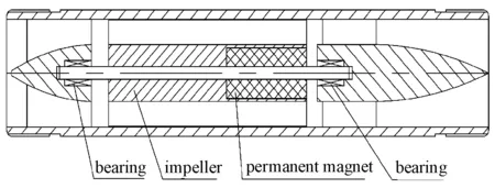
Figure 1.Structure of axial flow blood pump
The mesh diagram of the axial-flow blood pump model is shown in Figure 2, the number of mesh nodes is 282 951 and the number of mesh elements is 1 602 855. The role of the main blades is to boost the pressure and the role of the added pre-guide blades and post-guide blades is mainly used to guide the flow. The fluid separation is decreased in the main blades after the fluid is guided by the pre-guide blades, then the relative stabilize fluid is formed after the fluid is guided by the post-guide blades.
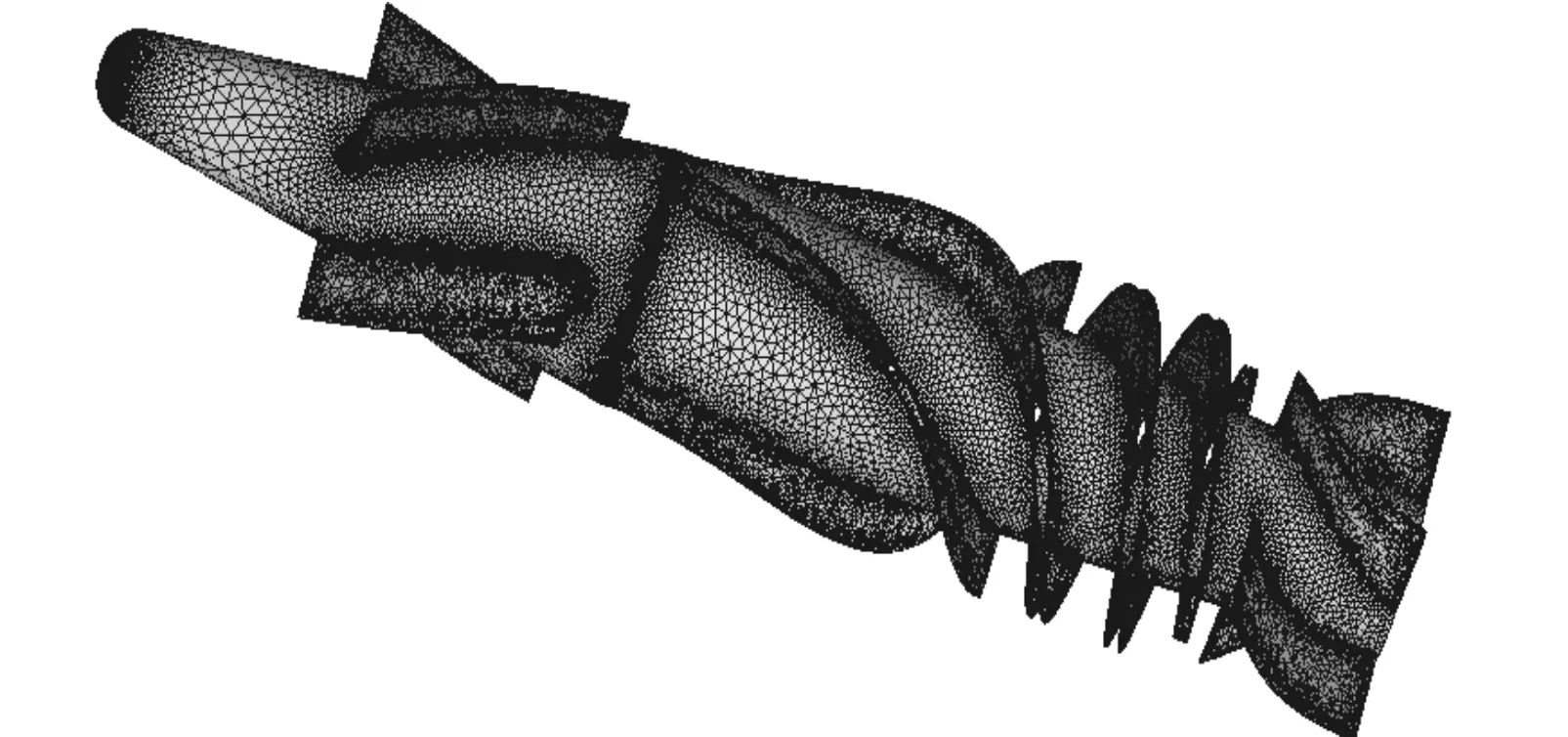
Figure 2.Grid of the blood pump
1.2.The settings of the calculation
Generally, the heartbeat of an adult is about 60~80 per minute, and the average value is 75. The blood output of the heart is 4~6 quart per minute and increases to 15~20 quart per minute during the strenuous exercise. The total output of elder is equal to the younger (1 quart=1.136 liters). ① The blood output of the heart (the outlet blood flow of the blood pump) is normally 4.544~6.816 L/min, and averagely 5 L/min; during the strenuous exercise, it increases to 17.04~28.4 L/min, and averagely 22.7 L/min. ② The pressure difference between the pump inlet and outlet is 100 mmHg, namely 13.3 kPa.
According to the above working conditions of the heart, the working conditions of the blood pump can be divided into three different types. The numerical calculations for the working conditions are shown in Table 1. The results show that the inlet condition is the mass flow and the fluid is the incompressible non-Newtonian fluid, thus the outlet condition is also considered as the mass flow. Hence, in the following analysis, the mass flow inlet and outlet conditions are taken as the boundary conditions.
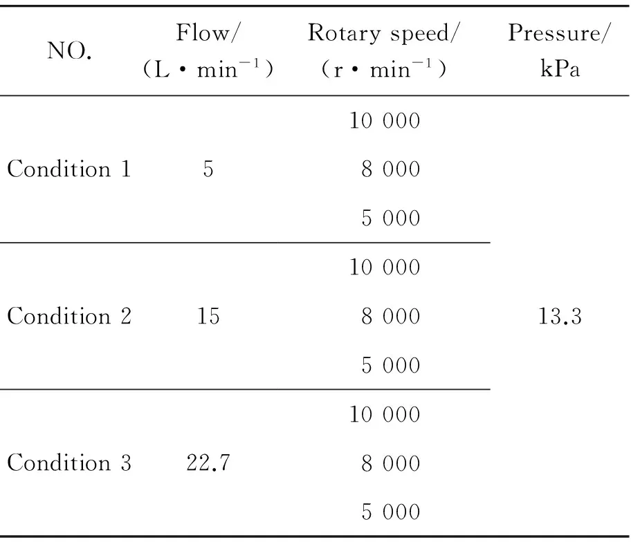
Table 1.Operation parameters of the blood pump
2.Analysis of the CFD simulation
2.1.The effect of rotary speed on the fluid field
Since the performance of the axial-flow blood pump is mainly affected by the rotary speed, for studying the pressure distribution and the velocity distribution under different rotary speeds, the flow rate is set as 5 L/min, the pressure and velocity distribution and the streamlines are investigated under the rotary speed of 10 000 r/min, 8 000 r/min and 5 000 r/min as indicated in Figures 3~5, respectively.
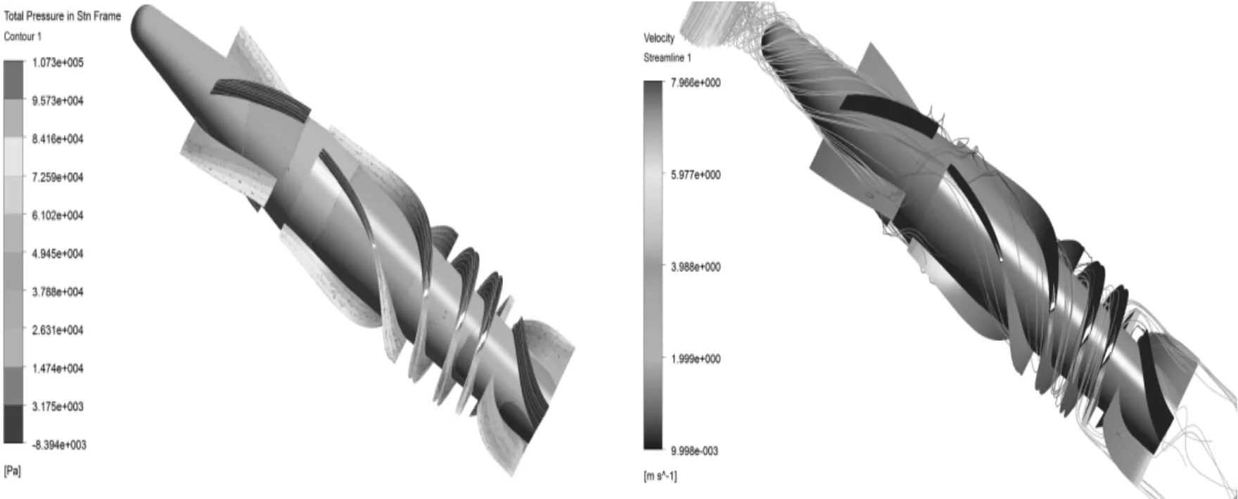
Figure 3.Pressure and velocity distribution of the fluid under 10 000 r/min and 5 L/min
It can be seen from Figures 3~5 that the maximum pressure and velocity changes increase with the increase of the rotary speed, which indicates that the pressure of the blood pump and the micro-friction gradually increase with the increase of the rotary speed, thus, the blood is damaged and results in the blood dissolve and thrombus. The pressure changes are not obvious with the increase of the rotary speed and the maximum and minimum pressures are almost the same, which is mainly resulted from the inlet and outlet conditions of the fluid field.
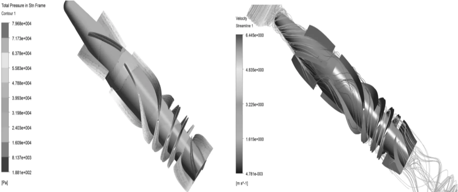
Figure 4.Pressure and velocity distribution of the fluid under 8 000 r/min and 5 L/min
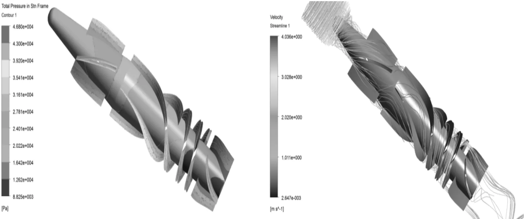
Figure 5.Pressure and velocity distribution of the fluid under 5 000 r/min and 5 L/min
2.2.The effect of flow rate on the fluid field
The flow rate is also an important performance for the axial-flow blood pump. Therefore, it is necessary to analyze the pressure distribution of the blood pump under the different flow rate. The rotary speed of the blood pump is set to 10 000 r/min, and the fluid pressure and velocity distribution diagrams under 5 L/min, 15 L/min and 22.7 L/min are obtained, as shown in Figures 6~8.
It can be seen from Figures 6~8 that the maximum total pressure of the blood pump model increases obviously with the increase of the flow rate, indicating that the pressure of the blood pump increases gradually with the increase of the flow rate, and the blood is gradually damaged by the micro-friction, resulting in the blood dissolve and thrombus. Meanwhile, when the flow rate reaches to 22.7 L/min, the pressure increases dramatically. Therefore, the performance of the designed axial-flow blood pump under 22.7 L/min will be further studied.
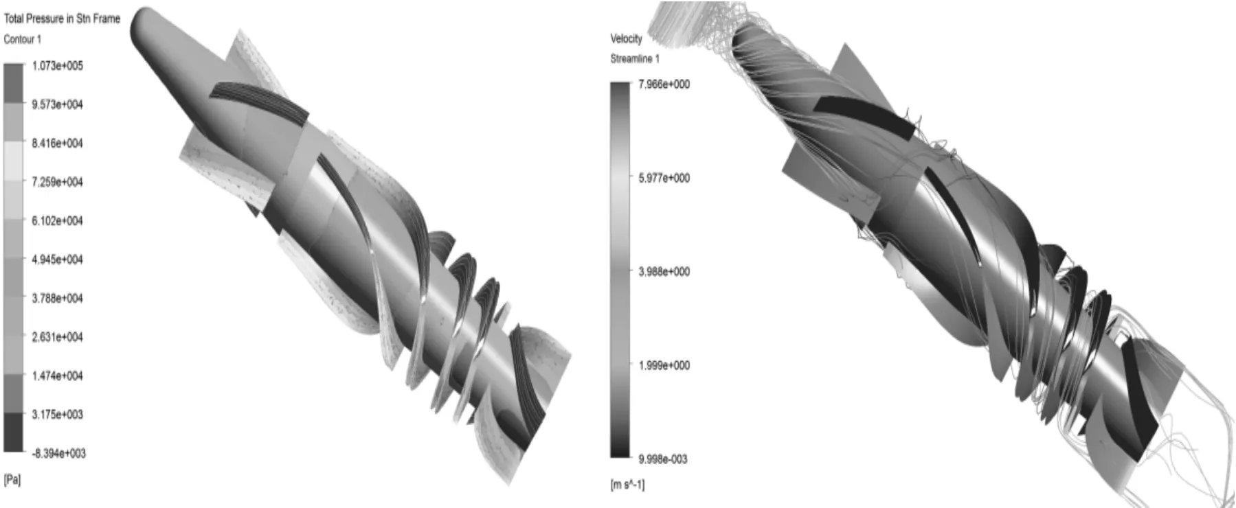
Figure 6.Pressure and velocity distribution of the fluid under 10 000 r/min and 5 L/min
Figure 7.Pressure and velocity distribution of the fluid under 10 000 r/min and 15 L/min
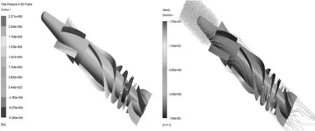
Figure 8.Pressure and velocity distribution of the fluid under 10 000 r/min and 22.7 L/min
3.Experiment
In order to verify the simulation of the fluid field and the actual performance of the designed blood pump, the experiment system of the blood pump was established and the schematic diagram is shown in Figure 9. The control pulse was output to the windings of the electromagnet by the SCM-controlled circuit, and the alternating magnetic field was obtained. Thus, the permanent magnet rotor which had a certain coupling distance to the electromagnet can be forced to rotate by the alternating magnetic field.
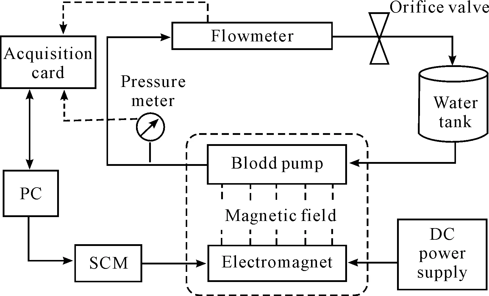
Figure 9.Schematic diagram of experimental system
3.1.Experimental condition
The photo of the experimental system is shown in Figure 10, which is mainly composed of 10 parts:
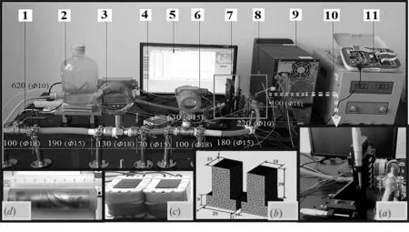
Figure 10.Monitoring experimental system of blood pump
(a) Electromagnet and mobile platform; (b) Iron core structure and size; (c) Electromagnet; (d) Blood pump
1.Orifice valve;2.Water tank;3.Flowmeter;4.12 V switching power supply;5.Monitoring interface;6.Pressure meter;7.Electromagnet;8.Blood pump;9.PC;10.DC power supply;11.SCM control system
① The PC (contains Sign 5 and 9 as shown in Figure 10);
② The SCM control and acquisition system (Sign 11);
③ The experiment circuit of the blood pump (contains Sign 1 and the whole plastic circuit);
④ The water tank (Sign 2);
⑤ The flowmeter (Sign 3, the type is LWGY-15C1 and the accuracy is 0.01 L/min );
⑥ The pressure meter (Sign 6, the type is OT-V80 and the accuracy is 0.01 kPa);
⑦ The electromagnet (Sign 7 and the Figure 10(a~c));
⑧ The blood pump (Sign 8 and the Figure 10(d));
⑨ The DC power supply (Sign 10, whose range is 0~120 V/5A);
⑩ The 12 V switching power supply (Sign 4, the function is to supply the power for the flowmeter and the pressure meter).
Besides, a mixture fluid of water and glycerin in the ratio 2∶1 was used as the experimental fluid, whose viscosity and characteristics are similar to blood[12].
3.2.Experimental procedure and results
It is found from the test of the designed blood pump that the maximum output flow rate is only about 7 L/min, when the rotary speed of the blood pump is 10 000 r/min and the output pressure is 13.3 kPa. For the existing driving system, the rotary speed cannot be higher.
If the mechanical loss of blood pump is ignored, the maximum output power under 10 000 r/min can be expressed as follows:
P10k= 13.3 kPa*7 L/min = 1.55 W
(1)
Then the maximum output power of 8 000 r/min and 5 000 r/min can be obtained as well as follows:
P8k= 13.3 kPa*4 L/min = 0.89 W
(2)
P5k= 13.3 kPa*1.1 L/min = 0.24 W
(3)
Therefore, the outlet pressure of the pump was adjusted by the damping valve of the test loop under different rotary speed in order to test the stability of the output flow rate under the corresponding rotary speed. Then the corresponding constant pressure value under 5 000 r/min, 8 000 r/min and 10 000 r/min of 5 L/min and 15 L/min can be obtained according to the formula (1~3), as shown in Table 2.
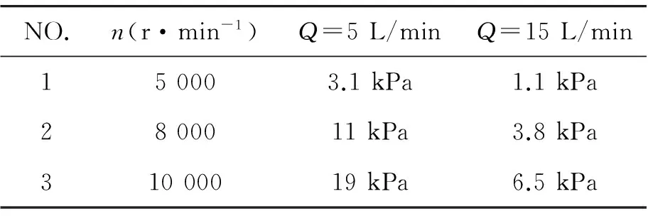
Table 2.The maximum pressure under 5 000 r/min, 8 000 r/min and 10 000 r/min of 5 L/min and 15 L/min
According to the pressure value as shown in Table 2, the experimental procedure can be prepared as follows:
1) The rotary speed was set to 5 000 r/min, and the outlet pressure was adjusted as 3 kPa. The digital flowmeter was used to test the outlet of the blood pump for 10 times. After averaging theses values, the test flow rate were compared with the theoretical values (5 L/min) as shown in Table 3.
2) The rotary speed was set to 8 000 r/min and 10 000 r/min, and the pressure was 11 kPa and 19.2 kPa, respectively. The outlet flow rate of the blood pump was tested for 10 times using the same method. After averaging theses values, the test flow rate were compared with the simulation values of the fluid field as shown in Table 3.
3) The experiments were conducted under the different rotary speed of 5 000 r/min, 8 000 r/min and 10 000 r/min in the working condition 2 (Flow rate: 15 L/min) as shown in Table 4.
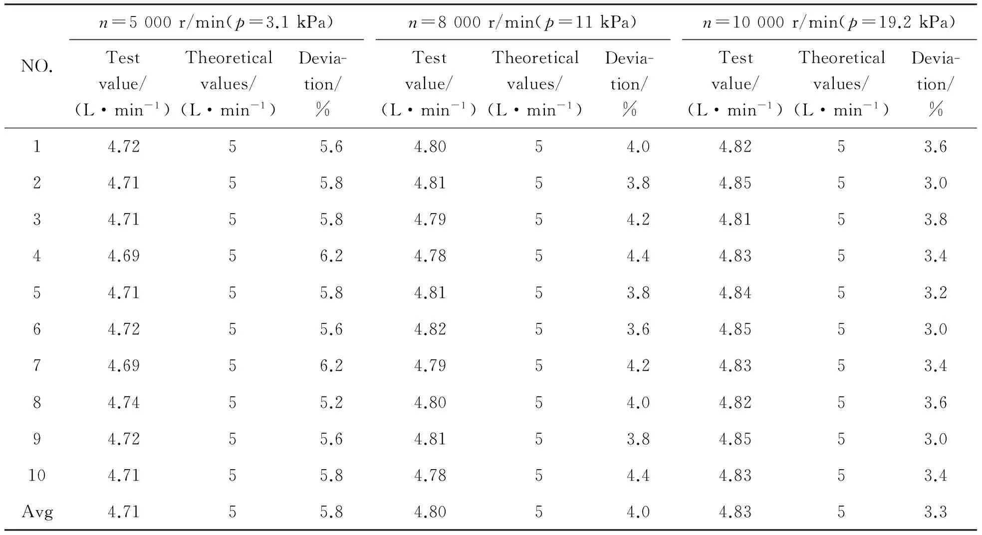
Table 3.Experiment data of the blood pump under condition 1(5 L/min)
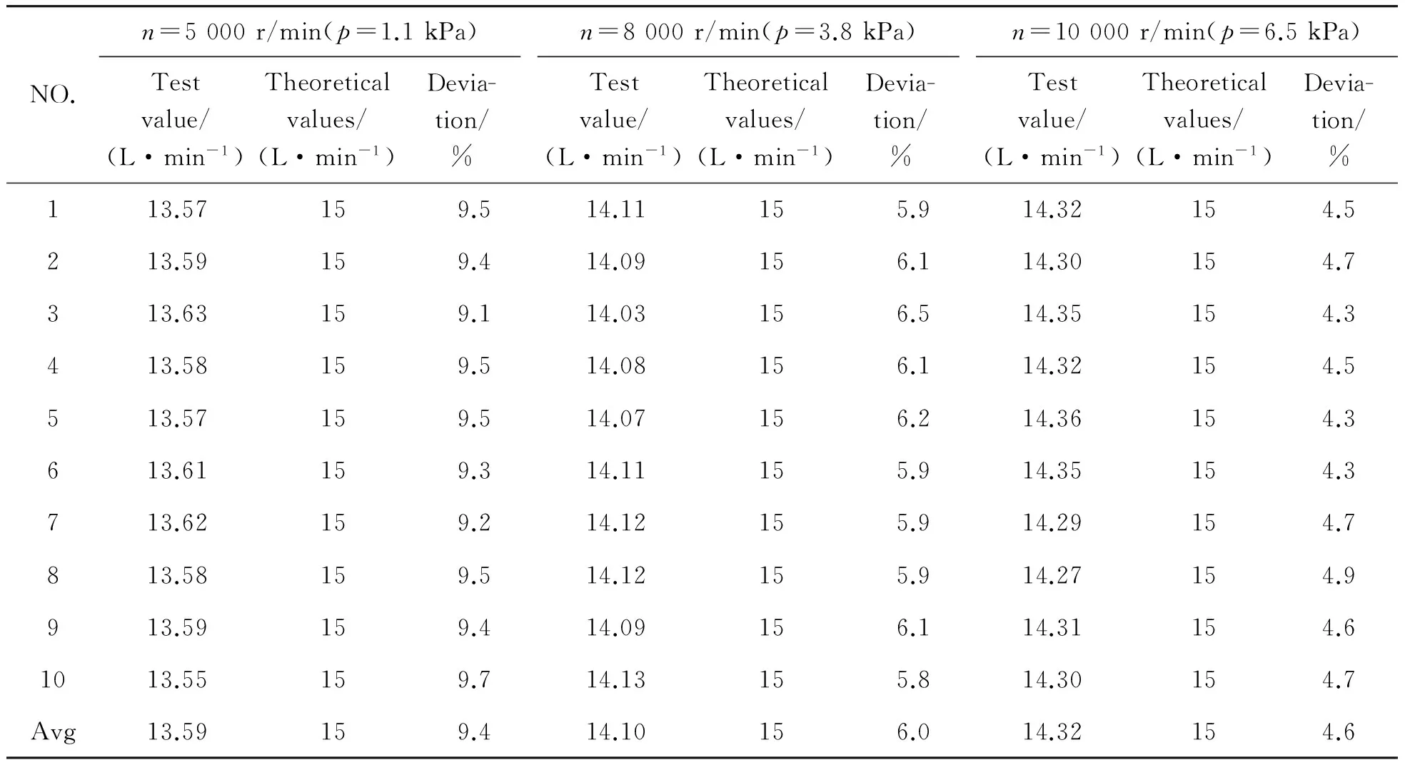
Table 4.Experiment data of the blood pump under condition 2(15 L/min)
3.3.Discussion
The experimental values are compared with the theoretical values and the deviations of the results are calculated under different pressures as shown in Figure 11.
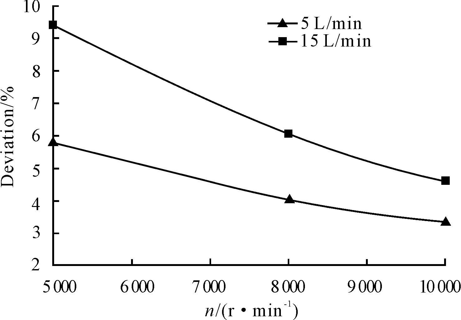
Figure 11.The experimental deviation analysis
It can be seen from Figure 11 that:
1) The deviations of the experimental and theoretical values gradually decrease with the increase in the rotary speed. When the rotary speed reaches to 10 000 r/min, the errors of the 2 conditions are all less than 5%, thus the precision of the test is considered in the allowed range.
2) The deviations of the experimental and theoretical values gradually increase with the increase in the flow rate. When the flow rate is set to 5 L/min and the rotary speed is above 6000 r/min, the deviations under different rotary speed are all less than 5%. However, when the flow rate is set to 15 L/min and the rotary speed is below 10 000 r/min, the deviations are all more than 5%, thus, the deviations are considered beyond the allowed range.
3) The above results show that the designed blood pump can basically meet the requirements in high rotary speed. However, the actual performance had a large deviation to the simulation design, and the deviation may become larger with the increase in the flow rate. Therefore, the designed blood pump needs to be further optimized.
4.Conclusion
The effects of the rotary speed, flow rate on the outlet and inlet fluid field and the effects of the guide blades on the fluid field were investigated though the CFD simulation analysis of the axial-flow blood pump. Moreover, the water pump test of the designed blood pump was conducted and the parameter outputs of the flow rate, pressure and so on in the axial-flow blood pump were tested. The experimental results show that the tendency of the designed blood pump is consistent with the simulation results. However, the outlet pressure is a few smaller when meeting the requirement of the output flow rate, indicating that it needs to be further improved and optimized.
References
[1]Zhang J, Johnson P C, Popel A S. Effects of erythrocyte deformability and aggregation on the cell free layer and apparent viscosity of microscopic blood flows[J]. Microvascular Research, 2009(77): 265-272.
[2]Tomioka J, Miyanaga N. Effect of surface roughness of mechanical seals under blood sealing[J].Lubrication Science, 2010(22): 443-452.
[3]YUN Zhong, TAN Jianping, XU Xiandong. Study and Simulation Analysis on the Hurt Principle of the RBC Impact[J]. Journal of Biomedical Engineering Research,2006,25(1):20-23.
[4]McCarty W J, Luan A, Siddiqui M, et al. Biomechanical properties of mixtures of blood and synovial fluid[J]. Journal of Orthopaedic Research, 2011(29): 240-246.
[5]YUN Zhong, TAN Jianping and GONG Zhongliang. Study of CFD Smiulation on Embedded Axial Blood Pump[J]. Machine Design & Research, 2006, 22(4): 111-115.
[6]Dong-Wook Kim, Mitamura Y. Prediction of hemolysis in intra-cardiac axial flow blood pumps for optimization of the impellers[J].Transactions of the Korean Institute of Electrical Engineers, 2002, 51(9):431-437.
[7]Chua P, Su B, Lim T M, et al. Numerical Simulation of an Axial Blood Pump[J]. Artificial Organs, 2007(31):560-570.
[8]Chulte-Eistrup S, Takano T, Maeda T.CFD studies ofClE3 Gyro centrifugal blood pump[J]. ASAIO Journal,2000,46(2):232.
[9]WANG Fangqun, FENG Zhigang, RU Weimin. The Evaluation of Hemolysis Index of the Permanent M aglev Impeller Pump[J]. Journal of Jiangsu University of Science and Technology, 2002: 63-65.
[10]WANG Fangqun, LI Lan, FENG gang. PredictioIl ofshear stress-related hemolysis in centrifugal blood pumps by computational fluid dynamics[J].Progress in Natural SciellCe, 2005, 15(10): 951-955.
[11]ZHANG Bao ning, ZHANG Yang jun, WU Yu lin, et al. Analysis of Flow Field in An Artificial Blood Pump with CFD[J]. Chinese Journal of Biomedical Engineering, 2002, 21(1): 41-45.
[12]SHI Fen. The Annulus Flow Field Analysis and Structure Optimization of the Embedded Axial Blood Pump[D]. Changsha: Central South University, 2012.
(Continued from 23 page)
DOI:10.3969/j.issn.1001-3881.2014.06.002
Received: 2013-10-15
*Project sponsored by National Natural Science Foundationof China (51075403, 31271057), Research Fund for the Doctoral Program of Higher Education of China (20100162110004) and National Youth Natural Science Foundation of China (51105385)
† Jian-ping TAN, Professor. E-mail:jfg_zju@126.com
- 机床与液压的其它文章
- Influence of salt fog test on the performance of the composite coating on avionics cases
- Control of EPS with regulating factor
- Numerical simulation of the double suction balance type screw compressor working process*
- Design and implementation of a wireless electronic inverter welding machine*
- A Sort of fusion control strategy for uncertainty complex process with large time lag*
- Cam profile optimization design of variable cycle reciprocating piston engine*

