Method for Measuring Residual Stresses Induced by Boring in Internal Surface of Tube and Its Validation with XRD Method*
Meng Longhui(孟龙晖),He Ning(何宁)***,Yang Yinfei(杨吟飞),Zhao Wei(赵威),Rong Bin(戎斌)
1.College of Mechanical and Electrical Engineering,Nanjing University of Aeronautics of Astronautics,Nanjing,210016,P.R.China;2.Shanghai Aircraft Manufacturing Co.,Ltd.,Shanghai,200436,P.R.China
1 Introduction
Residual stresses exist in most parts after machining,whose values are hard to accurately measure in most cases.Metal cutting is a process with high temperature,high strain,high strain rate,and large elastic-plastic deformations[1-2],and residual stresses exist in the superficial layer,whose depth is commonly no more than 0.2mm.However,the gradient in the thin layer is very high along the depth direction.The residual stresses can be attributed to several factors such as mechanical stresses,thermal stresses and phase transformations[3-4].The residual stresses induced by machining in the surface layer are an important factor that affects the workpieces stat-ics strength,fatigue strength,corrosion resistance,service life,geometric and dimension stability[5-7].Wang,et al.[8]studied the deformations caused by residual stresses generated by milling in aluminum alloy,and Miao,et al.[9]improved the surface property by shot peening.Generally speaking,the residual stresses play an important role in in-service performance of machined parts.Therefore,it is significant to measure the residual stresses induced by machining and reduce their harmful effects.
During the past years,different methods for measuring residual stresses have been developed.They can mainly be classified as destructive,semi-destructive and non-destructive techniques[10].The destructive and semi-destructive techniques,called mechanical methods,are dependent on inferring the residual stresses from the displacement measured after completely or partially relieving the stresses by removing material[11].Sectioning,contour,hole-drilling,deephole and ring-core are the principal destructive and semi-destructive techniques used to measure the residual stresses in structural members[10-11].Non-destructive techniques include neutron or X-ray diffraction,magnetic methods and ultrasonic methods.These techniques usually measure some parameters related to the stresses[12-15].X-ray diffraction(XRD)method is commonly used to measure the surface residual stresses,as the penetration depth of X-rays in common metals is very shallow(just few microns).A layer removal technique must thus be used in association with XRD method to measure in-depth stresses.It is recognized that the XRD equipment is very expensive,and the XRD method is just applicable to materials that are crystalline and relatively fine grained[16],which are serious drawbacks.Therefore,this paper presents a strain-based method using much cheaper equipment to measure the residual stresses induced by boring in internal surface of the tube.The correctness of the strainbased method will be validated by the results obtained from the XRD method later in this paper.
2 Calculation Principle
The theory of calculating residual stresses in the internal surface of tube is based on the variations of the axial length and the external diameter when removing the internal stress layers,which was first presented by Mesnager in 1919[15].Authors improve the calculating method and put it into practice here.
Assuming that the tube is so long that it can be disposed as a problem in a plane(an appropriate length of the tube will be determined by finite element method(FEM)in what follows).The internal radius of the tube is RIN,and the external radius ROUT.σZ,σT,σRare the stresses along the axial,tangential and radial directions in the tube,respectively.A schematic representation of the residual stresses in the tube is shown in Fig.1.
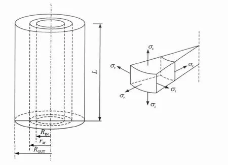
Fig.1 Schematic representation of the residual stress in tube
The average value of the residual stress in the layer from radius RINto radius rMisσ(rM).When removing this layer,it equals to applying the force of the same magnitude in the reverse direction on the newly exposed surface of the rest part after the layer removal.HereσZO,σTOandσROare the stresses along the axial,tangential and radial directions on the outside surface induced by the internal layer removal.There is no force on the internal surface in the radial direction before layer removal,and thusσROis 0.According to the Lame cylinder theory,it can be concluded that

LetεZO,εTO,εROrepresent the strains along the axial,tangential and radial directions on the outside surface.The relationship between the stresses and the strains on the external surface is as follows
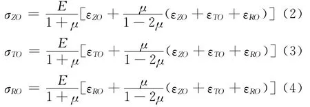
where E andμare the elasticity modulus and poisson ratio of the material,respectively.AsσROis 0,it can be obtained by

From Eqs.(1,3,5),another equation can be written as

Moreover,the axisymmetric plane equilibrium should be satisfied,i.e.

If there is no external force applied to the part,the equilibrium equations along the axial and tangential directions should be satisfied as follows

The residual stress along the tangential direction can be obtained from Eqs.(6,7)

In Eq.(10),SROUT=πR2OUT,S=πR2M.When the internal layer from radius RINto radius rMhas been removed,the residual stresses in the rest part can be assumed to be redistributed uniformly.Based on this assumption and Eq.(8),another equilibrium equation can be obtained

Taking a derivative with respect to rMof Eq.(11),we have

The residual stress along the axial direction can be derived from Eqs.(2,5,12)

In conclusion,the residual stresses in three directions induced by boring in the internal surface of the tube can be obtained from Eqs.(6,10,13).
3 FEM Validation of Tube Length
The aforementioned equations are deduced on the very long tube assumption,but in practice it is not the case.For the convenience and accuracy of the measurements,FEM is used to find an appropriate length of the tube in this paper.
The tube model,created by Abaqus 6.10 software,has a 45mm external diameter and a 41mm internal diameter.As presented in Ref.[2],when the length of the tube is over 6times of the external diameter,the measurement accuracy will be high enough.Here the length of the tube is first set as 450mm to ensure a very high accuracy.Since the residual stresses along the radial direction are so small in a real part that they can be ignored in the model,the model is just loaded with the residual stresses along the axial and tangential directions.Here an input file calculated by MATLAB is used to load the residual stresses,and the stress values in the cylindrical coordinate should be transmitted to the rectangular coordinate with the following equation

With the command″initial conditions,type=stress,input=S.dat″,the stress file is imported.Here the residual stresses applied to the model can be seen as a typical case of residual stresses induced by boring.
After loading the residual stresses(Fig.2),the gradient of the stresses along the depth direction is extremely high,which is the main characteristic of the residual stresses induced by machining.To simulate the experimental process of removing material layers by corrosion,the technology of″element birth and death″is used to″kill″the elements in the internal surface of the model layer by layer.The strains on the outside surface along the axial and tangential directions are recorded after″killing″each layer.Here the recorded strains are in the mid-height of the model.In the experiments,the strain gauge should also be installed in the mid-height of the tube.
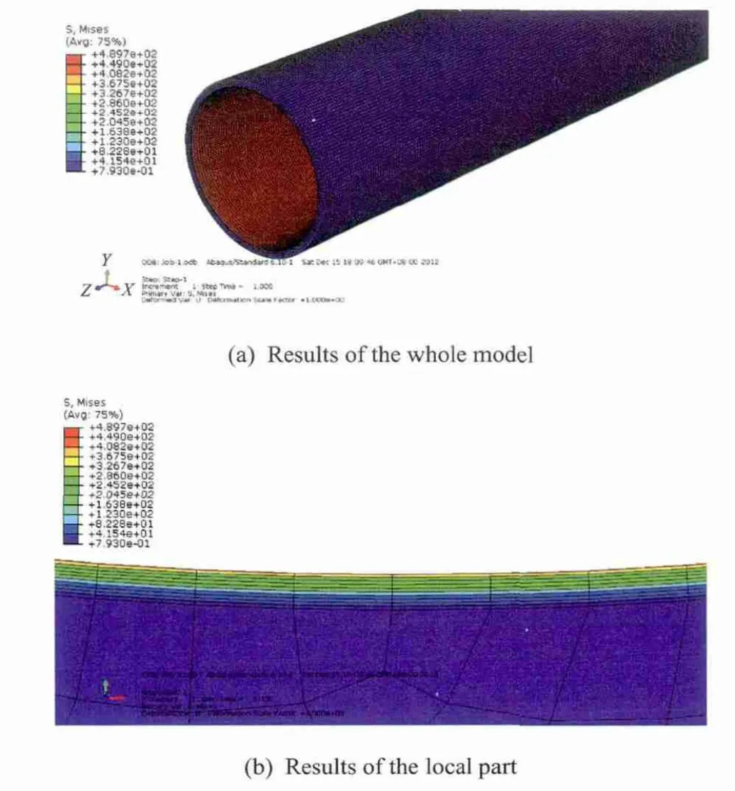
Fig.2 Results of the model after imposing residual stress
The accuracy of the results obtained from the above model is high.But the tube is too long,thus causing lots of inconvenience and material wastage.A new model with the same internal and external radii is created to have a different length along the axial direction.The strains obtained from the long model mentioned above is set as references to see how long the new model should be in order to gain accurate results.
Here,Python language is used to create the model and make the second development to Abaqus.The tube length is first set as 20mm.The tube length is increased by an increment of 5mm each time.The calculated strains and the references are compared to find out whether the accuracy is high enough.Fig.3gives a schematic representation of the second development,where the high accuracy is defined as that the maximum error is no more than 0.1×10⁻⁶.
The analytical result indicates that when the tube length reaches 50mm,the accuracy can meet the requirement.Therefore,it can be concluded that the 50mm tube length is long enough to obtain an accurate result.The result can give some guidance to the related projects in practice,that is,as the tube diameter changes,if the ratio of tube length to external diameter is no less thanλ=50/45=1.11,the accuracy will be high enough.
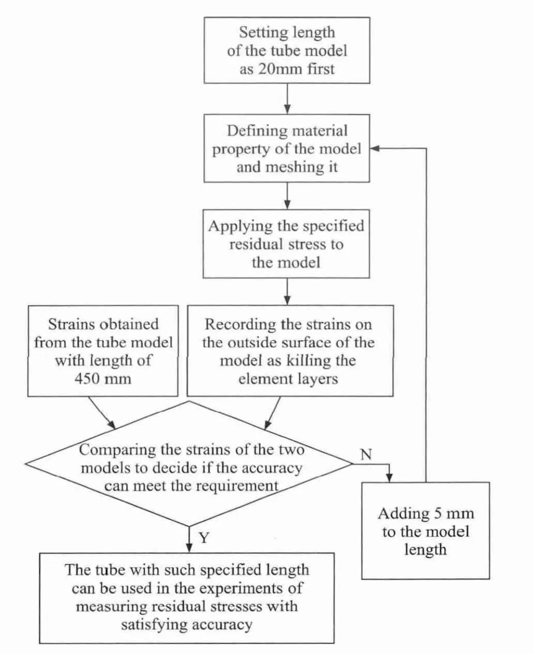
Fig.3 Schematic of the second development
4 Validation of Strain-Based Method with XRD Method
To validate the correctness of the strainedbased method,a comparison should be made between the results obtained from the strain-based method and those from XRD method.
The tube used in experiments(Fig.4(a))is made of Ti6Al4V.First,annealing treatment is performed on the tube to remove the initial residual stresses.The external and internal diameters are 50mm and 41mm,respectively.The internal material layers are removed by chemical corrosion which will not introduce any new residual stress to the rest part.According to the relationship between the depth of the removed layer and corrosion time,the time should be precisely controlled to make sure that for each time the depth of the removed layer is 10μm.After finished corrosion,the chemical reagent is washed away immediately.When the tube reached the room temperature,the strains in the tangential and axial directions are recorded.Since temperature has a significant effect on the measuring results,and the room temperature cannot always stay the same,temperature compensation must be accomplished here.After each layer removal and the corresponding strains recording,the residual stresses on the internal surface of the tube are also measured by the XRD method,using aportable Proto-LXRD machine and employing the following parameters:tube voltage of 30kV,tube current of 25mA,irradiated area of 1mm×3mm and the sin2φmethod.

Fig.4 Tube to be measured and the strain meter equipment
Removing the stress layers surely causes some relaxation and redistribution of the residual stresses,and thus the results from the XRD method should be compensated in order to obtain correct stress values.
After Moore and Evans published their paper in 1958,few literatures can be found on the development of correction method for layer removal[17-18].The correction method proposed by Moore and Evans for plates and cylinders is still the most commonly used one,that is
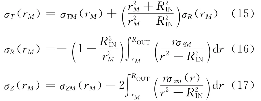
whereσT,σR,σZare the corrected circumferential,radial,axial stresses,respectively.σZMand σTMare the measured residual stresses in the axial and tangential directions,while ROUT,RINand r are the external,internal and actual measurement radii,respectively.
Eqs.(15-17)are based on several assumptions:(1)Circumferential layer removal should not introduce any new residual stress to the rest of the part.It is well-known that corrosion will not cause any new residual stress,and the material layers are thus removed by chemical corrosion here.(2)The tubes to be measured must be long enough and the measurement location should be far away from the edges.In this paper,the tube used in the experiments is not very long,just 50 mm.According to the finite element analysis,the accuracy is acceptable when the measurement is performed in the middle height of the tube.(3)The residual stresses to be measured are either plane symmetric or rotationally symmetric[18].Here in this paper,the residual stresses induced by boring is highly rotationally symmetric.(4)During the relaxation and redistribution caused by layer removal,the stresses must always remain elastic.In our experiments,the residual stresses induced by boring are certainly far from elastic limit of the material.Hence,it will not cause any plasticity during relaxation and redistribution.
In general,these assumptions are all satisfied here.Therefore,the measured residual stress can be corrected by Eqs.(15-17).
5 Results and Discussion
The residual stress profiles obtained from two methods are shown in Fig.5.The residual stresses in the axial and tangential directions induced by boring are all compressive in the outmost layers.The magnitude of the stress along the tangential direction is greater than the one along the axial direction.Besides,the depth of the layer with compressive residual stress is about 60μm in both directions.
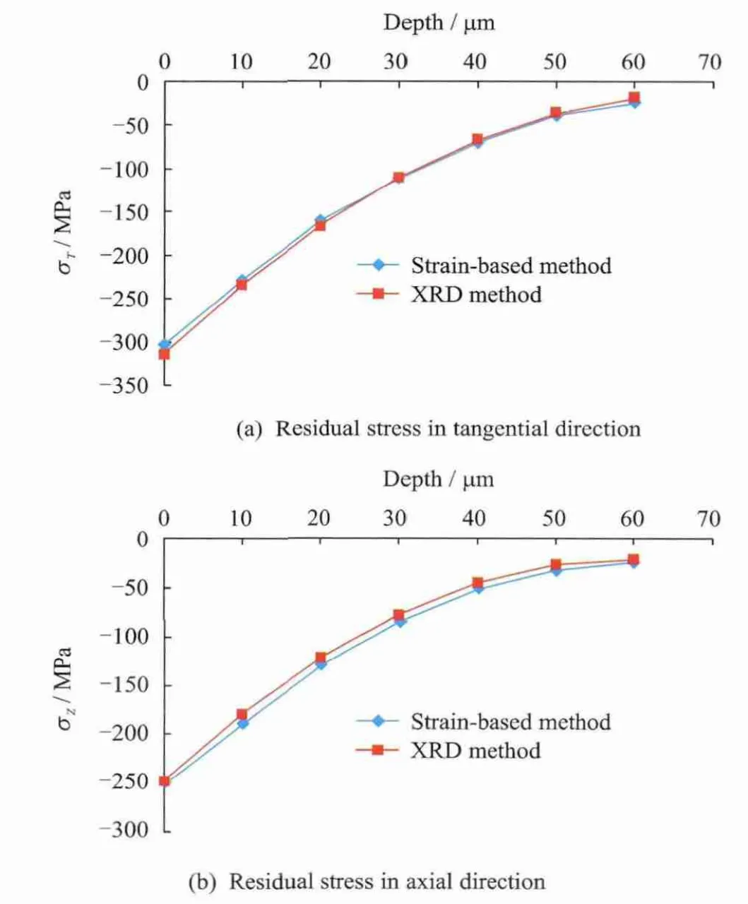
Fig.5 Residual stress measured by two methods
The stress profiles along both the axial and the tangential directions obtained from the two methods agree well with each other.The maximum error between the two results is less than 10 MPa,which can be ascribed to the limit of the measuring equipment.The margin of error from this method is no more than±10MPa,which can be accepted in most cases.By analyzing the obtained results,it can be concluded that the accuracy of the strain-based method proposed in this paper is high enough and it can be used to measure the residual stresses in the internal surface of the tube in practice.
6 Conclusions
A strain-based method is proposed to measure the residual stresses induced by boring in internal surface of the tube,and it is based on the strains on external surface of the tube.The results of the finite element analysis show that if the ratio of tube length to external diameter reaches no less thanλ=50/45=1.11,the accuracy will be high enough for both strain-based measuring method and the correction method proposed by Ref.[18].The measurements obtained from strain-based method are compared with those obtained from XRD method.Both the stress profiles correspond to each other very well and the validity of the strain-based method has thus been confirmed.Therefore,the proposed method can provide stress profiles with high accuracy and can take the place of XRD method in practice in some cases with much cheaper equipments.
[1] Withers P J,Turski M,Edwards L,et al.Recent advances in residual stress measurement[J].International Journal of Pressure Vessels and Piping,2008,85:118-127.
[2] Ge W H.The analysis of the residual stress in Spinning tube parts[J].Metal Forming Machinery,1985(3):2-12.(in Chinese)
[3] Yu X X,Lau W S,Lee T C.A finite element analysis of residual stress in stretch turning[J].Int J Mach Tools Manufact,1997,37(10):1525-1537.
[4] Liu C,Zhang J X,Wu B,et al.Numerical investigation on the variation of welding stresses after material removal from a thick titanium alloy plate joined by electron beam welding[J].Materials and Design,2012,34:609-617.
[5] Wang Q C.Evaluation and relief of residual stress in aluminum alloys for aircraft structures[D].Hangzhou:College of Mechanical and Energy Engineering,Zhejiang University,2003:4-7.(in Chinese)
[6] Larsson C,Holden T M,Bourke M A M,et al.Measurement and modeling of residual stress in a welded Haynes 25cylinder[J].Materials Science and Engineering,2005,A(399):49-57.
[7] Grzesik W,Zak K.Surface integrity generated by oblique machining of steel and iron parts[J].Journal of Materials Processing Technology,2012,212:2586-2596.
[8] Wang H F,Zuo D W,Dai S,et al.Milling Deformations of Jointed 7022Aluminum Alloy by FSJ[J].Journal of Nanjing University of Aeronautics &Astronautics,2013,45(2):245-249.(in Chinese)
[9] Miao H,Zuo D W,Wang H J,et al.Surface Characteristic of 10Ni3MnCuAl Steel by Shot Peening[J].Transactions of Nanjing University of Aeronautics and Astronautics,2009,26(3):178-183.
[10]Mirzaee-Sisan A,Fookes A J,Truman C E,et al.Truman residual stress measurement in a repair welded header in the as-welded condition and after advanced post weld treatment[J].International Journal of Pressure Vessels and Piping,2007,84:265-273.
[11]Yan D J,Liu X S,Li J,et al.Effect of strain hardening and strain softening on welding distortion and residual stress of A7N01-T4aluminum alloy by simulation analysis[J].Journal of Central South University of Technology,2010,17:666-673.
[12]Navas V G,Gonzalo O,Bengoetxea I.Effect of cutting parameters in the surface residual stress generated by turning in AISI 4340steel[J].International Journal of Machine Tools &Manufacture,2012,61:48-57.
[13]Pratihar S,Stelmukh V,Hutchings M T,et al.Measurement of the residual stress field in MIG-welded Al-2024and Al-7150aluminium alloy compact tension specimens[J].Materials Science and Engineering,2006,A(437):46-53.
[14]Sebastiani M,Eberl C,Bemporad E,et al.Depth-resolved residual stress analysis of thin coatings by a new FIB-DIC method[J].Materials Science and Engineering,2011,A(528):7901-7908.
[15]Carrera E,Rodríguez A,Talamantes J,et al.Measurement of residual stress in cast aluminium engine blocks[J].Journal of Materials Processing Technology,2007,189:206-210.
[16]Rossini N S,Dassisti M,Benyounis K Y,et al.Methods of measuring residual stress in components[J].Materials and Design,2012,35:572-588.
[17]George D,Smith D J.Through thickness measurement of residual stress in a stainless steel cylinder containing shallow and deep weld repairs[J].International Journal of Pressure Vessels and Piping,2005,82:279-287.
[18]Rossini N S,Dassisti M,Benyounis K Y,et al.Methods of measuring residual stress in components[J].Materials and Design,2012(35):572-588.
[19]Azanza Ricardo C L,D′Incau M,Scardi P.Revision and extension of the standard laboratory technique for X-ray diffraction measurement of residual stress gradients[J].Appl Crystallogr,2007,40:675-83.
[20]Moore M G,Evans W P.Mathematical correction for stress in removed layers in X-ray diffraction residual stress analysis[J].SAE Trans 1958,66:340-345.
 Transactions of Nanjing University of Aeronautics and Astronautics2014年5期
- Transactions of Nanjing University of Aeronautics and Astronautics的其它文章
- Optimal Control Strategy for Buck Converter Under Successive Load Current Change*
- Predictive Modeling and Parameter Optimization of Cutting Forces During Orbital Drilling*
- Wear Behaviour of Electroless Ni-P-Diamond Composite Coatings*
- Theoretical and Experimental Investigation of Laser Milling Assisted with Jet Electrochemical Machining*
- Structural Design and Control Strategy Analysis of Micro/Nano Transmission Platform*
- Friction and Wear Properties of Amorphous Carbon Nitride Coatings in Water Lubrication*
