Erratum to:"Finite Element Analysis of Discrete Circular Dislocations"[CMES,vol.60,no.2,pp.181-198,2010]
K.P.Baxevanakis and A.E.Giannakopoulos
The authors wish to apologize for any inconvenience caused due to the fact that no figures were published in the original article.Please find in the following pages the omitted graphs.We note that in the original article,Figs.7a and 7b are erroneously referenced as 6a and 6b.
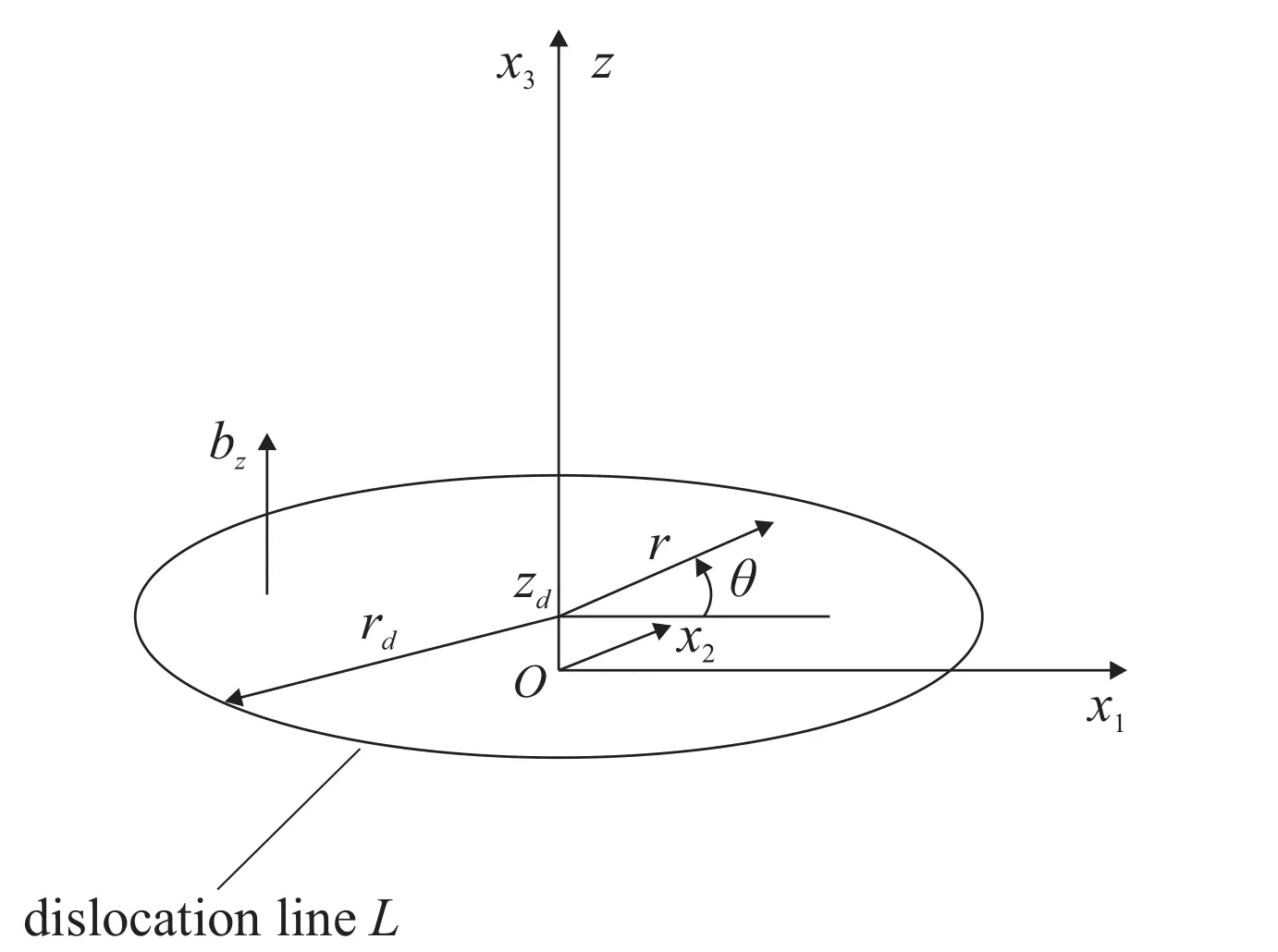
Figure 1:The geometry of a circular dislocation loop.
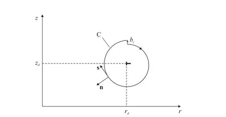
Figure 2:Axisymmetric Volterra type dislocation.The position of the dislocation line is(rd,zd).
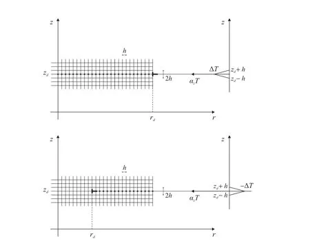
Figure 3:The implementation of the thermal analogue to finite elements.
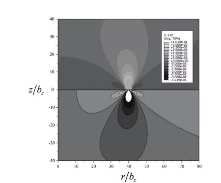
Figure 4a:The normalized stress σrz/G for W.On the upper part are the finite element results and on the lower the theoretical solution.The isocontours range is(-0.03,0.03).
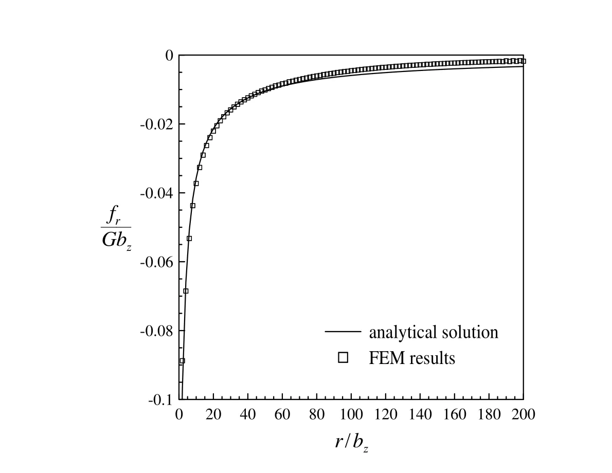
Figure 4b:The normalized dislocation loop self-force per unit length fr/Gbz analytical solution and numerical results for W.
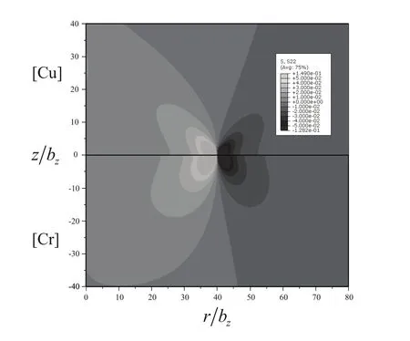
Figure 5a:The normalized stress σzz/G for Cu and Cr.On the upper part are the finite element results for Cu and on the lower for Cr.The isocontours range is(-0.05,0.05).
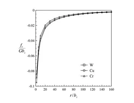
Figure 5b:The normalized dislocation loop self-force per unit length fr/Gbz numerical results for W(isotropic),Cu and Cr(anisotropic).
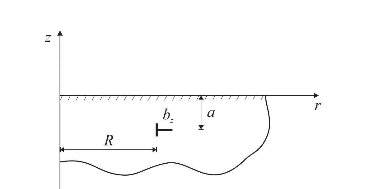
Figure 6:The geometry of a circular dislocation loop near a free surface.
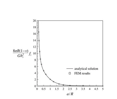
Figure 7a:The normalized force per unit length analytical solution and numerical results for W.
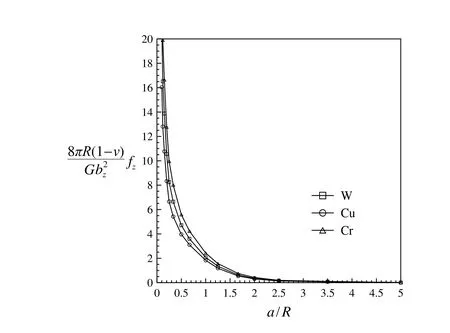
Figure 7b:The normalized force per unit length numerical results for W,Cu and Cr.
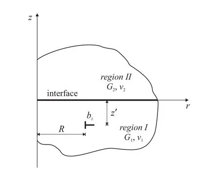
Figure 8:The geometry of a circular dislocation loop in a two phase material.
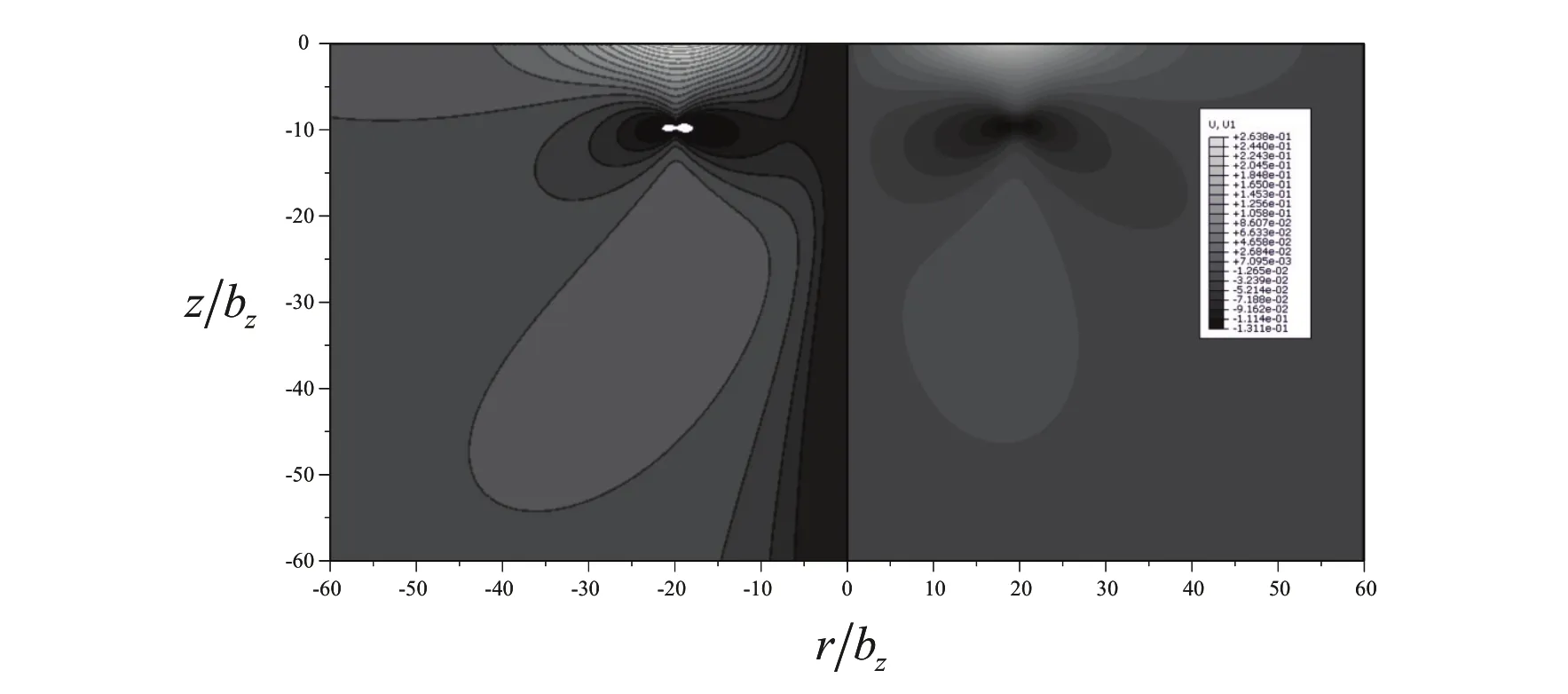
Figure 9a:The normalized displacement ur/bz for a dislocation loop near a free surface in Cu.On the left part is the analytical solution and on the right the finite element results.The isocontours range is(-0.143,0.302).
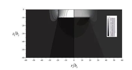
Figure 9b:The normalized displacement uz/bz for a dislocation loop near a free surface in Cu.On the left part is the analytical solution and on the right the finite element results.The isocontours range is(-0.225,0.943).
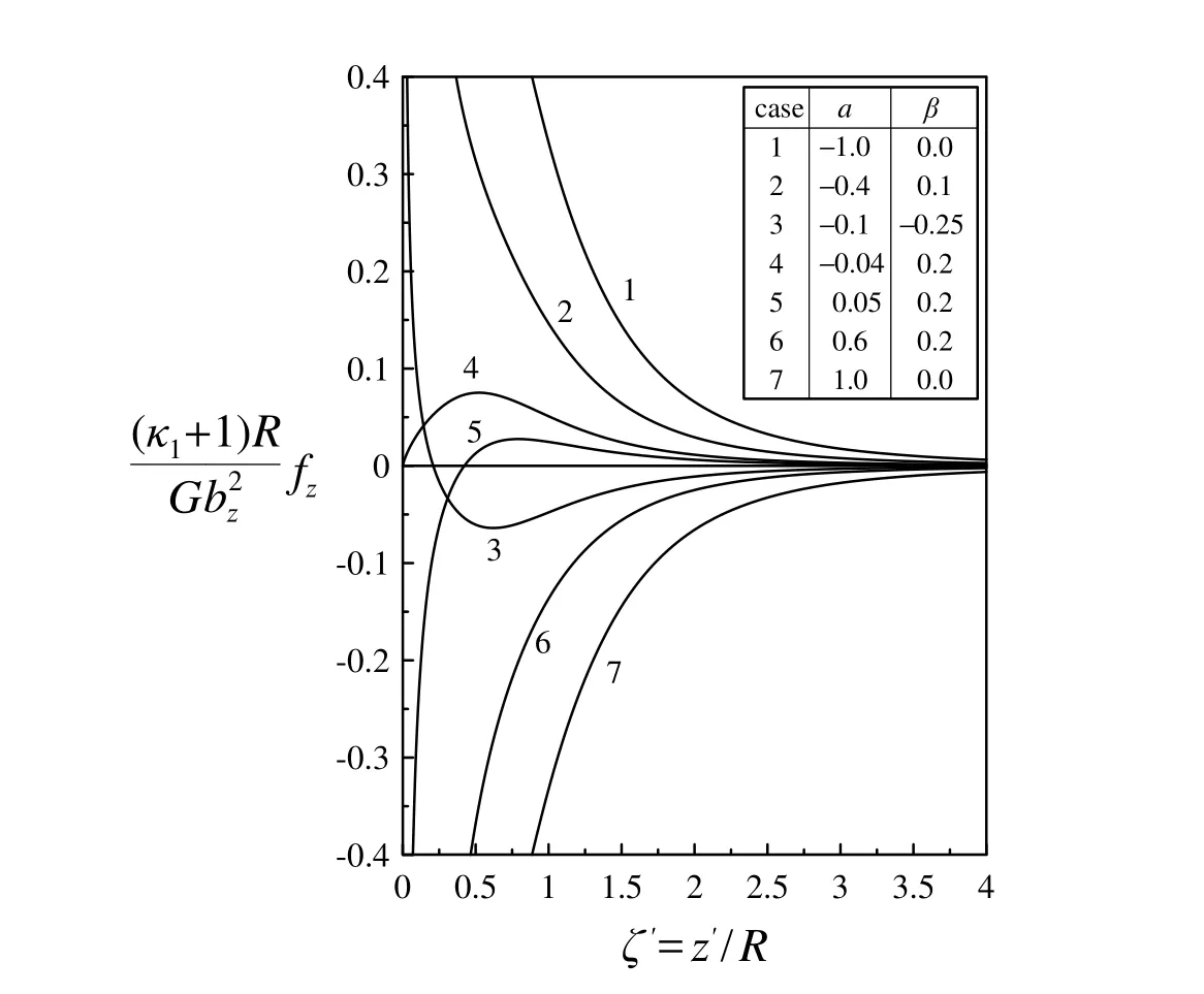
Figure 10a:The normalized force per unit length analytical solution.
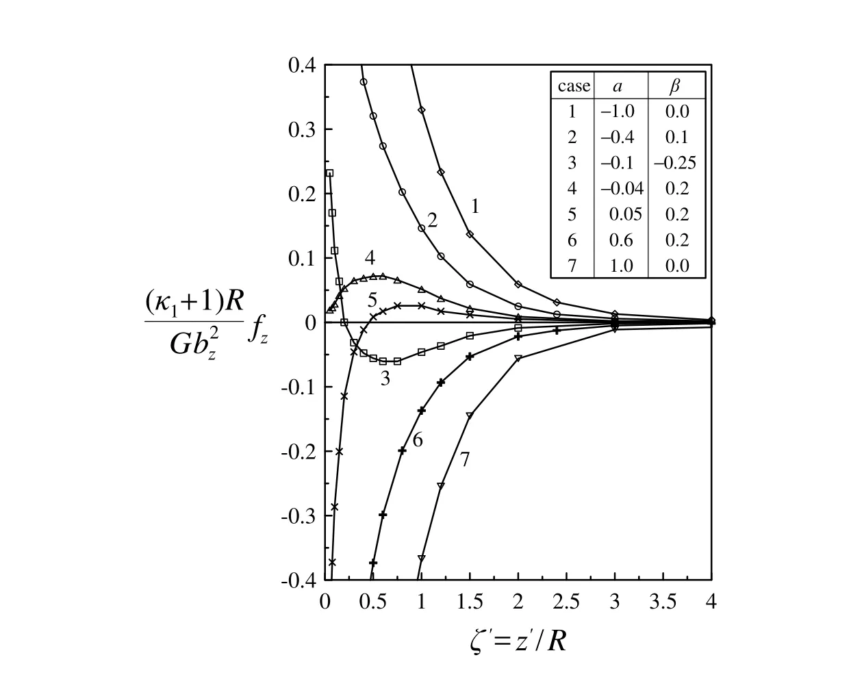
Figure 10b:The normalized force per unit length numerical results.
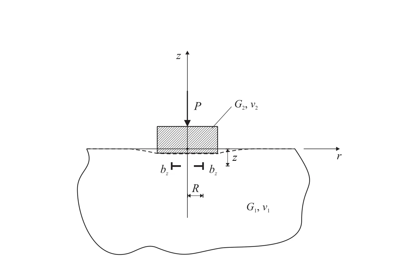
Figure 11:Indentation of a medium that contains a dislocation loop.
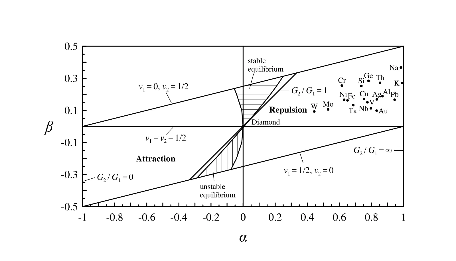
Figure 12a:Classification of materials behavior in the α-β plane for Diamond indenter.
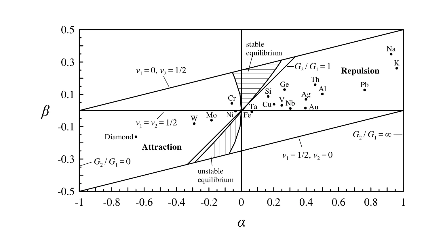
Figure 12b:Classification of materials behavior in the α-β plane for steel(Fe)indenter.
Baxevanakis,K.P.;Giannakopoulos,A.E.(2010):Finite Element Analysis of Discrete Circular Dislocations.CMES:Computer Modeling in Engineering&Sciences,vol.60,no.2,pp.181-198.
 Computer Modeling In Engineering&Sciences2014年6期
- Computer Modeling In Engineering&Sciences的其它文章
- Composite Simpson’s Rule for Computing Supersingular Integral on Circle
- Symmetric Coupling of the Meshless Galerkin Boundary Node and Finite Element Methods for Elasticity
- Meshless Local Petrov-Galerkin Mixed Collocation Method for Solving Cauchy Inverse Problems of Steady-State Heat Transfer
