
Cabin Noise Control on Large Oil Tankers
2014-03-16 08:14:20WUWenweiYINXuewen
船舶力学 2014年12期
WU Wen-wei,YIN Xue-wen
(1 China Ship Scientific Research Center,Wuxi 214082,China;2 National Key Laboratory on Ship Vibration&Noise,Wuxi 214082,China)
1 Introduction
During the past several decades,ships travelling at sea have been dramatically increased in number as well as in total gross tonnage(GT).For instance,the GT of ships had been quadrupled between 1965 and 2003,at the same time,the number of commercial ships,such as oil tanker,bulk container,and cargo ships,had been approximately doubled.When the equipments installed onboard are operating,sound and vibrations are inevitably produced.Excessive noise levels can result in deterioration of working conditions,crewmembers’health,and bring discomfort to the passenger as well.Hence,the cabin noise is of great concern to both the ship designers and ship owners.
In general,cabin noise signals comprise not only low frequency discrete spectra due to rotating and reciprocating machinery but broad continuous spectra due to ventilation systems,propeller noise,and other resources.To address the broad characteristics of the cabin noise,finite element analysis(FEA),energy finite element analysis(EFEA)and statistical element analysis(SEA)have been employed,which can be found everywhere from the journals and conferences as well.As the results of perfect implementation of the above-mentioned methods in software engineering,some commercial software has been released including LMS Virtual Lab,VAONE[3],and ACTRAN.Though these software platforms are very powerful,almost none of them are tailored for the demands of engineers in early acoustic design stage,which requires more specific design procedures involving less input parameters.Hence,acoustic design engineers can be free from exhausting modeling works and data processing.
In addition,the problems of onboard noise including cabin noise have aroused the attention of international maritime society.In november of 2012,the draft code on noise levels of ships has been adopted by MSC91,aiming to provide international guidelines for protection against noise regulated by regulation[II-1/3-12]of the International Convention for the Safety of Life at Sea(SOLAS).According to the ship specifications[1],prior to the delivery of the vessel,its noise levels shall be measured at conditions as specified in the revision of IMO Noise Code Resolution A.468-XII.The vessels shall comply with the noise requirements upon the delivery of ships,among which,the cabin noise limits are listed in Tab.1.
Hence,fast evaluation techniques and software which are tailored for acoustic engineers and have more specific features and functions in early design stage than those commercial software platforms have been eagerly demanded.In this paper,our cabin noise prediction software based on SEA is presented.Then,cabin noise of a large oil tanker is modeled and noise levels at different locations of the tankers are predicted.Finally,according to the requirements of the noise level limit in code[1],two measures are taken to ensure the predicted levels below the limits.
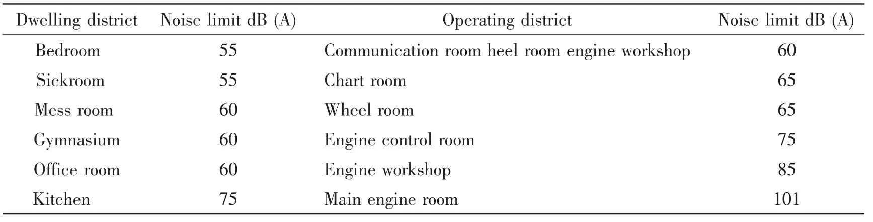
Tab.1 Cabin noise level limit[1]
2 Numerical modeling and implementation
When the ships are travelling at sea,the excitation sources,vibration transmission paths,and the coupling between sources and receivers via the transmission path are the major parameters that determine the vibration and sound levels of the receiving components,i.e.,cabin room,operating platform,and etc.In this section,the major vibration and noise sources are summarized,the major transmission path affecting the structure-borne noise is analyzed,and finally,fast cabin noise modeling based on SEA is proposed and implemented.
2.1 Noise sources on the oil tanker
Propeller cavitations and pressure fluctuation are dominant vibrating sources responsible for excessive vibration and noise of the ships.Structure-borne noise and air-borne noise due to the main engines and the auxiliary equipments are also considered as major sources of cabin noise.In addition,the emission noises from exhaust chimney and from the ventilation fans in the engine room have great impact on the noise levels in the cabins.In our cabin noise software,the above major sources are embedded within and vibration data,i.e.,acceleration,velocity,and/or sound pressure levels for typical main engines,electric motors,and propellers are also provided.
2.2 Vibration and noise transmission path analysis
Structure-borne noise and air-borne noise are the two major mechanisms for cabin noise.When the main engines and auxiliary equipments are operating,their vibration will be transmitted from the engines,via isolators,supporting bases,and bulkheads,etc.,to the shell structures throughout the entire ship.This is called structure-borne path,along which,the vibration energy can flow from the engines to any parts throughout the ship.As a result,cabin noise is produced.As for the air-borne noise,the air within the cabins can act as elastic components through which vibration and sound energy can be transmitted to adjacent cabins.
It is also noted that,from the point view of structure-borne noise,waves can propagate freely within the plate and shell structures until they encounter discontinuities such as the joins and junctions.Reflection would occur at these discontinuities which makes the effectiveness of vibration transmission path change significantly.
2.3 Numerical approach based on SEA
As mentioned in Section 1,the cabin noise consists of not only low frequency discrete spectra but also high frequency broadband spectra.The popular finite element method cannot handle this situation when the dynamic systems possess high modal density and has uncertainty in modal parameters.Hence,in our cabin noise software,Statistical Energy Analysis(SEA)is employed.
The SEA allows for much straightforward description of the system,in which the entire dynamic system is partitioned into several subsystems,each can be explicitly represented by internal energy,coupling loss factors,and internal loss factors.The internal energy of the subsystems is function of modal density and major geometry parameters.The dissipated energy is determined by transmission loss at junctions and internal damping,as well.
In this software,typical beams,plates,shells,and their junctions are modeled;accordingly,the data of the coupling loss factors with respect to different junctions are collected from the published literature[2].Material damping factors for sound absorbing materials are also available.
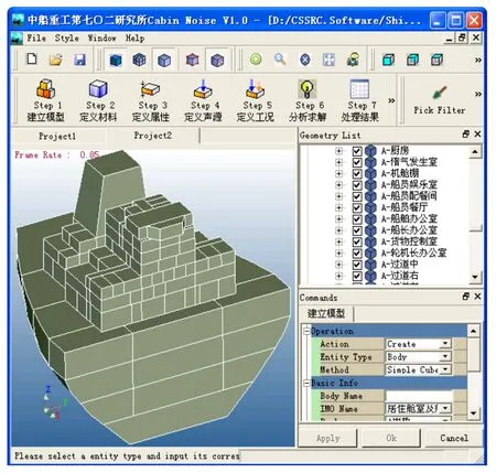
Fig.1 SEA model for large oil tanker
2.4 SEA model development
The SEA model for the large oil tanker in early design stage is shown in Fig.1,which consists of several subsystems,mainly including vibrating sources,ship architectures,and acoustic cavities.The vibrating sources are two main engines and six auxiliary electric motors,the data of which will not be disclosed due to confidentiality.The acoustic cavities are specified with the acoustic parameters of the cells within the ship,which include the air density,bulk modulus,and the sound absorption coefficients of the acoustic layer on the wall,and so on.Typical cavities are the dining room,sick room,office,wheel room,etc.
3 Results and control measures
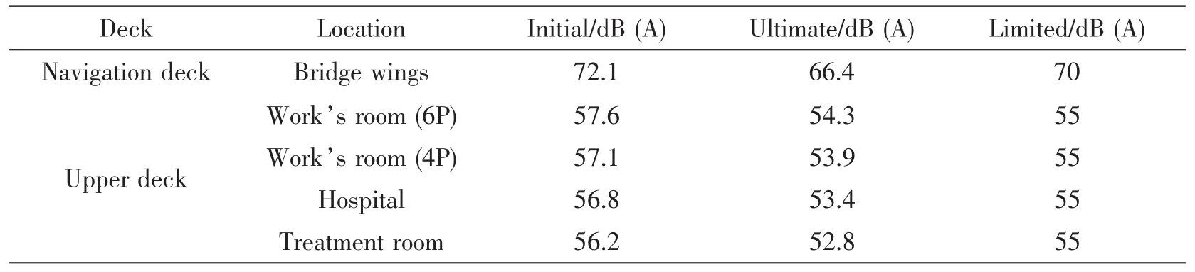
Based on the above SEA model,numerical calculation is performed.Cabin noise levels at different locations on board are listed in Tab.2.We can find that the sound pressure levels at most locations are fairly below the allowed limits derived from code[1]except bridge wings on navigation deck and room on upper deck.To better illustrate the predicted sound levels on different decks,sound levels are plotted in Figs.2-8.
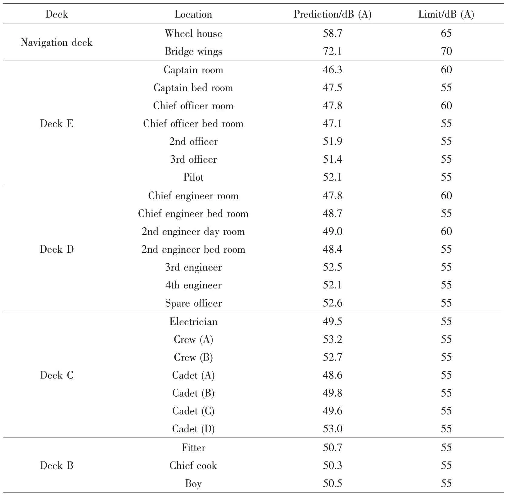
Tab.2 Cabin noise level results for oil tanker
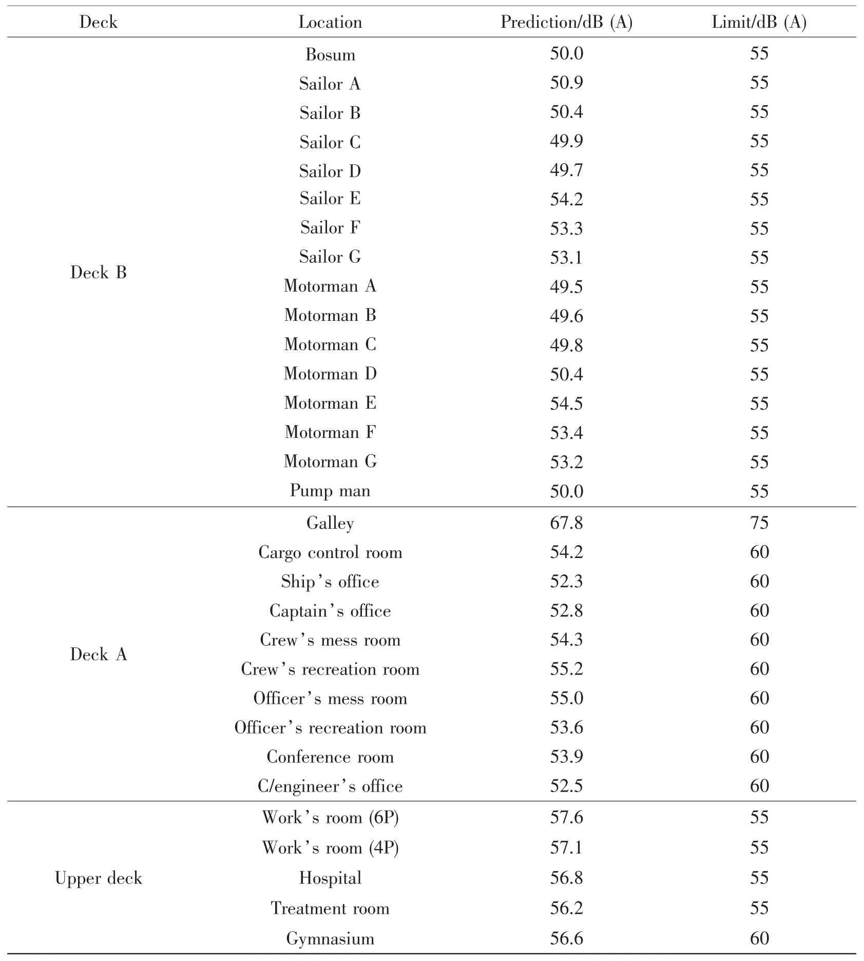
Continue 2
It is found from Tab.2 that the noise levels in the accommodation spaces on the main deck exceed the limit of 55dB(A).And the noise levels on two wings of the navigation room also can not meet the limit requirements according to the guidelines[1].This implies that we should make some changes on the preliminary design so as to lower the sound levels at these locations.Two recommendations of noise control measures have been proposed in the updated design.
Floating floors are used in all of the accommodation rooms on the main deck in order to suppress the vibration transmission from the main engines and auxiliary equipments.In addition,the internal structure of the exhaust stacks of engine chamber can be designed to be sound absorption channel with micro-perforated plate.After taking the above two noise control measures,the noise levels in various spaces and cabins are able to meet the limit requirements of guidelines[1],which are listed in Tab.3.
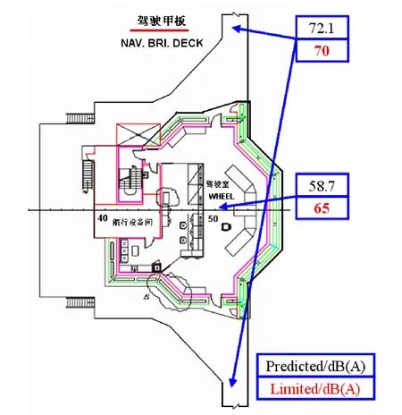
Fig.2 Predicted noise levels on navigation deck
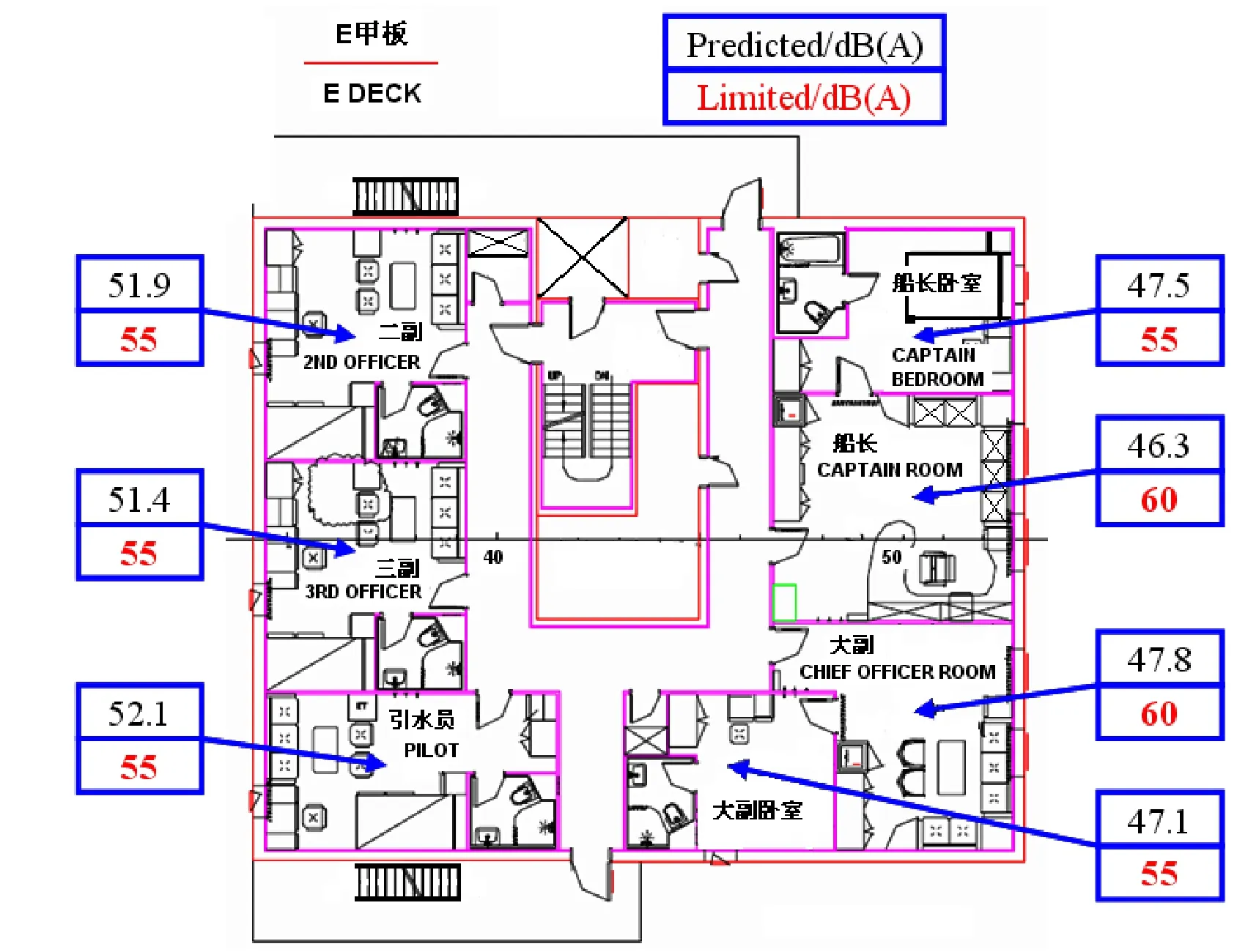
Fig.3 Predicted noise levels on deck E
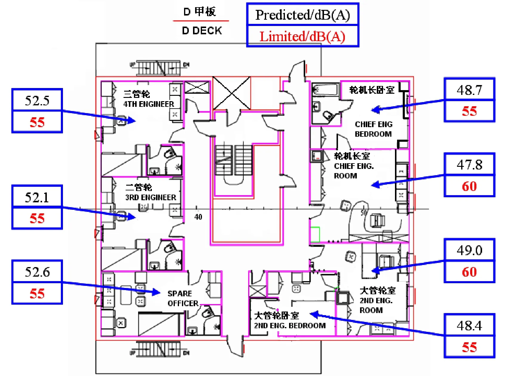
Fig.4 Predicted noise level values on deck D
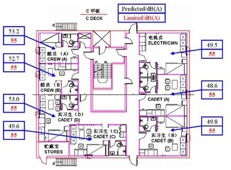
Fig.5 Predicted noise levels on deck C
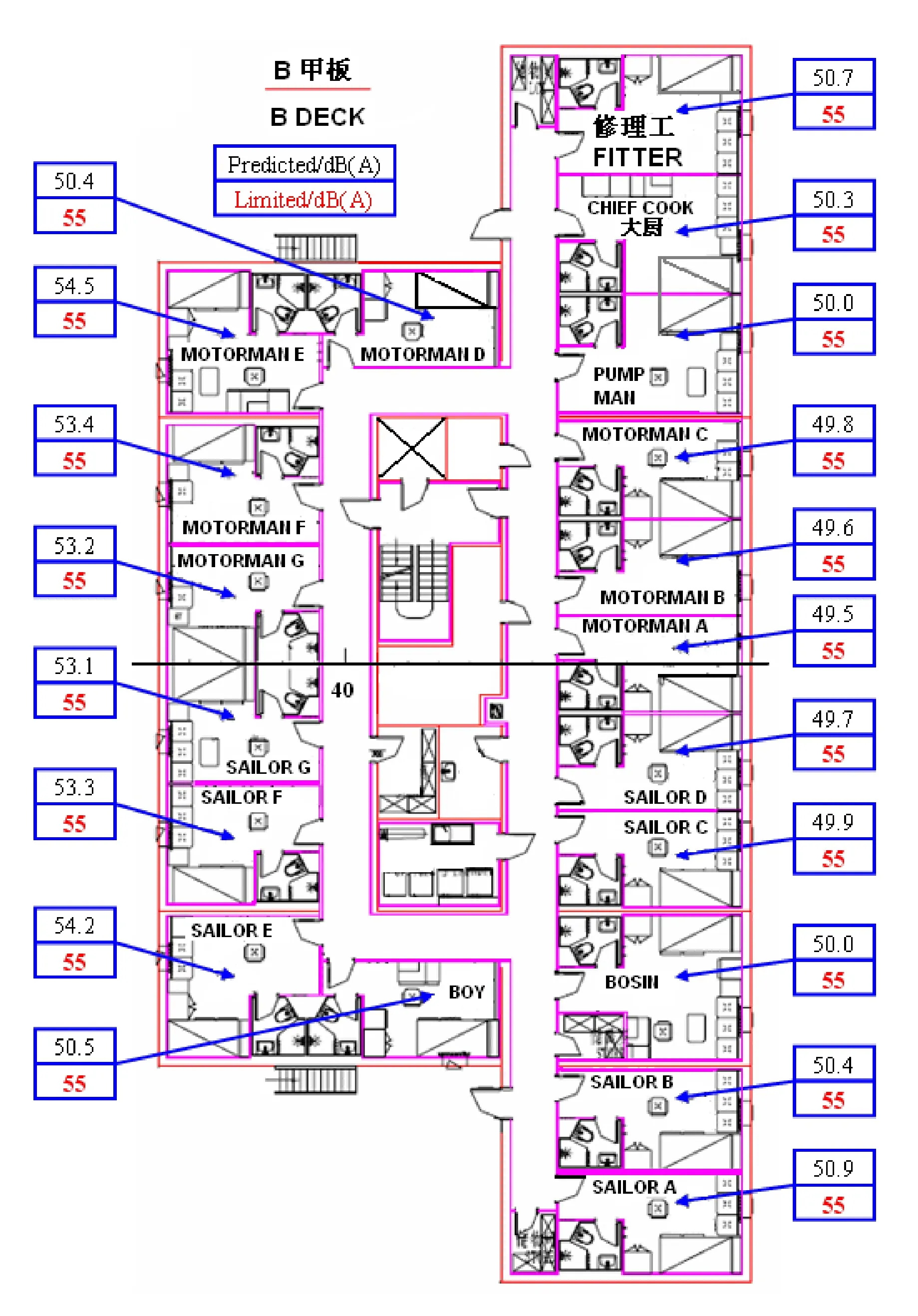
Fig.6 Predicted noise levels on deck B
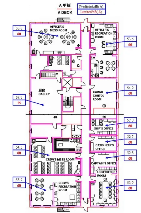
Fig.7 Noise levels on deck A
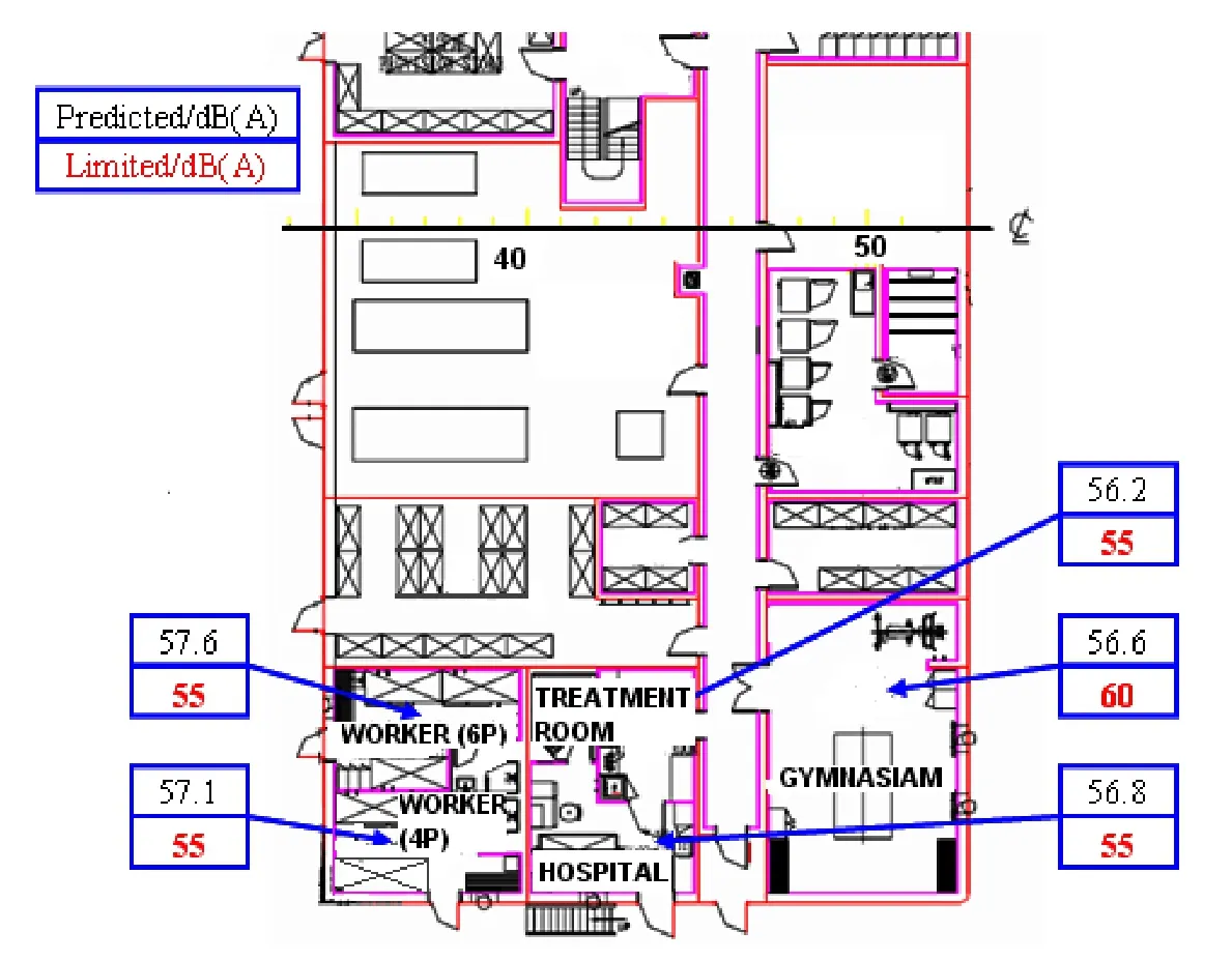
Fig.8 Noise level values on upper deck
Tab.3 Cabin noise levels after control measures
4 Conclusions
A fast modeling strategy for cabin noise based on SEA is proposed and implemented,which is tailored for acoustic engineers so that acoustic design can be performed more efficiently.In accordance to the characteristics of the major noise sources and ship structures,the cabin noise of a large oil tanker is analyzed based on SEA.Two measures are taken to suppress the noise levels of the cabins that exceed the noise level limits,which finally ensure the cabin noise meet the requirements in MSC337.This work shows that,compared to general commercial software,our cabin noise prediction platform is more efficient to help the engineers to make decisions on design modification and material selection.
[1]Noise levels on board ships:Code on noise levels[K].Technical Specification,MSC91.
[2]Layon Gilroy,David Brenna,Leo F,et al.Energy finite element analysis(EFEA)algorithms and software for ship noise[R].Technical report No.:NCE TM 05-029,2005,Noise Control Engineering INC,MA,USA.
[3]VAONE software release and Users’Guide[K].ESI INC.
- 船舶力学的其它文章
- 《船舶力学》稿约须知
- 总目次(2014年)
- A Review of Short-term Prediction Techniques for Ship Motions in Seaway
- Influence of Rotation Direction of Impeller on Noise Performance of Waterjet
- Research on the Design of Hull Crashworthiness Structure based on Sandwich Plate System
- Influence of Stress Wave on Dynamics Damage Character of Ship-build Low-carbon Steel Based on Low-velocity Taylor Impact Bar