
Influence of Rotation Direction of Impeller on Noise Performance of Waterjet
2014-03-16 08:14:18LILiuyangWANGYongshengFUJianYIWenbinWEIYingsanYANGQiongfang
船舶力学 2014年12期
LI Liu-yang,WANG Yong-sheng,FU Jian,YI Wen-bin,WEI Ying-san,YANG Qiong-fang
(College of Marine Power Engineering,Naval University of Engineering,Wuhan 430033,China)
1 Introduction
The main performance parameters of waterjet ship’s selection are fast(including speed and efficiency)and acoustic stealth(including pulse and radiated noise),the results about this have not been published yet at home.In this study,the validation numerical methods is used to provide technical support for the waterjet propulsion ship’s selection in which the fast and acoustic stealth are considered.For the actual waterjet propulsion ship,the non-uniform flow caused by the stern ramp angle and impeller interaction make a certain difference in radiated noise between the inward pump and outward pump.According to the published papers about the radiated noise of the waterjet propulsion system,abroad only SSPA Sweden company has considerable experience in radiated noise of the waterjet propulsion system.From the report:typical sound transmission for a waterjet can be:(1)Structural transmission from the rotor bearing into the hull and then emitted into the water;(2)Structural transmission of pressure pulses from the rotor blades onto the waterjet intake and then emitted into the water;(3)Direct emission of noise from the rotor into the water,which is the directly radiated noise that dominates in the whole frequency range,it is the main acoustic source[1].Most researchers engage in researching the noise of the no-propulsion pump,for example,Dong et al used the experimental method to study the effect of geometry on the flow structure and noise in a centrifugal pump.It is demonstrated that the primary sources of noise are associated with interactions of the non-uniform outflow from the impeller with the tongue[2].Reese et al compared the noise of the axial fan with the experimental data,the result shows that DES is able to predict broad band noise up to a frequency of 1 kHz and LES yields acoustic predictions which are satisfactory up to 5 kHz in test case[3].Timouchev et al analyzed the level of tone spectrum components,mainly these are blade-passing frequencies(BPF),finding there is a close link between the pressure pulsation in the pump working cavity and its vibration and noise level[4].Langthjem et al calculated the flow field and sound field of the two-dimensional centrifugal pump,finding that the sound generated in the centrifugal pump is determined mainly by the unsteady surface forces[5-6].Mou et al analyzed the main noise sources of the waterjet pump:load noise,inverse flow noise and cavitation noise[7].But there is no paper about the influence of rotation direction of impeller on noise performance of waterjet,this paper adopts the same idea and method with the Swedish SSPA company to analyze the influence of rotation direction of impeller on noise performance of waterjet.The result can provide some reference and help for the engineer.The rotation direction of impeller as shown in Fig.1.
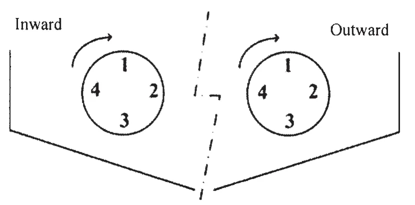
Fig.1 Rotation direction of impeller of waterjet pump
2 Principle of CFD
2.1 Governing equations
The governing equations for the turbulent incompressible flow encountered in this research are the steady-state RANS equations for the conservation of mass and momentum,given as:
where ρ is the density of the fluid,xiand xjare the coordinate components,are the mean velocity components,is the volume force,is the average pressure,μ is the molecu-lar viscosity,is the Reynolds stress[8].To correctly account for turbulence,the Reynolds stresses are modeled in order to achieve the closure of Eq.(2).The modeling is based on the Boussinesq hypothesis to relate the Reynolds stresses to the mean velocity gradients within the flow.The Reynolds stresses are given by

where μtis the turbulent viscosity and k the turbulent kinetic energy.
In order to accurately predict the waterjet pump noise,the relevant turbulent flow must be accurately described.In this paper,the interaction involving small-scale vortices between the non-uniform inflow and the impeller blades is investigated numerically.However,RANS simulation is based on time-averaged computation,which is inadequate to provide detailed fluctuating flow information.To combine the advantage of a RANS with the higher resolution of a LES,hybrid methods like DES(Detached eddy simulation)has been developed.The DES simulation improves predictions in transient flow by using LES(Large eddy simulation)to simulate separated flow and applying RANS only to treat the boundary layer.DES does not require the grid resolution in the near-wall region as fine as LES would,while it still works like LES in the region away from the wall where the large-scale structures are formed and convected.
2.2 Validating of numerical method
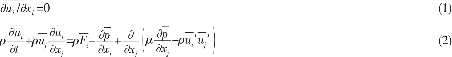
The mixed flow waterjet pump of KaMeWa71SII is used to verify the veracity of CFD and numerical model by calculating the hydraulic performance of the waterjet pump.The number of impeller blade is 6,the number of stator blade is 11,the diameter of impeller inlet is 710 mm and the diameter of nozzle is 446 mm.The computational domain is discreted by using the hexahedral block structured grids,which is shown in Fig.2.
The relative error of power between the calculated data and manufacture’s data is less than 1%,what is more,the calculation data is larger than the manufacture’s data,the reason is that the calculated data do not care about the friction loss between the pivot bearing in the hub and the thrust bearing,which is shown in Fig.3.The result directly verifies the veracity of using CFD to simulate the internal flow of waterjet pump,which is the base of calculating the dipoles source in the waterjet pump.
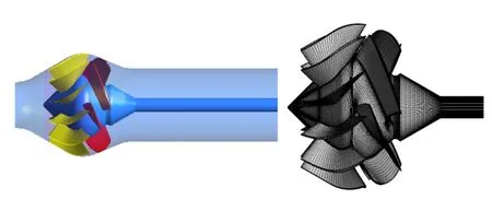
Fig.2 Geometry and mesh of waterjet pump
Fig.3 Comparison between numerical and manufacture powers
3 Calculation of the field of ‘hull+duct+waterjet’
3.1 Calculation of unsteady field of ‘hull+duct+waterjet’
The model length of monohull with double waterjet pumps is 4.067 m,the ramp angle behind the stern is larger than 7 degrees,the number of impeller blade of the axial flow waterjet pump is 7,the number of stator blade is 11,which is shown in Fig.4.
The hull and Waterjet pump are divided by the structured grid,the number of nodes of the model scale are 6.5 million,the hull is modeled as viscous surface where the first point off the wall is typically a y+distance of 30-200.The quality of the grid(Determinant>0.45,angle>9)can meet well the requirement of computation.Fig.5 show the mesh of hull and Waterjet pump.
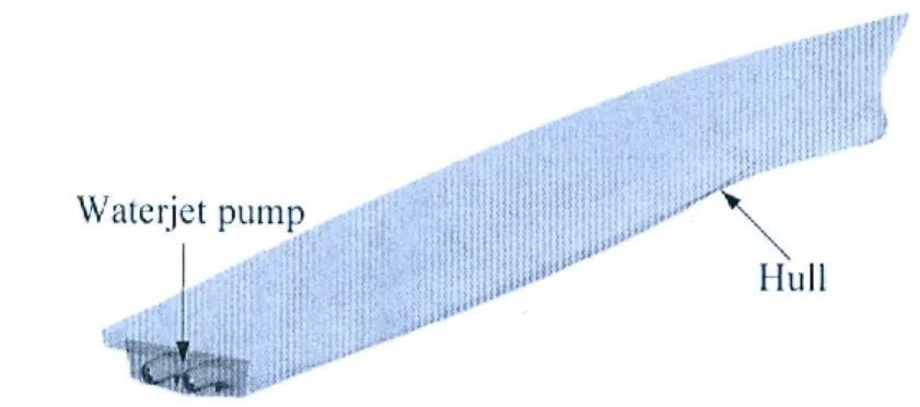
Fig.4 Geometry of waterjet pump and hull model
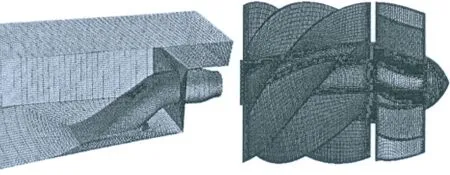
Fig.5 Hexad surface meshes of Hull and waterjet
The computational domain in this study extends 1L in front of the ship hull,3L behind the hull,1.5L to the side and 1.3L under the keel of the model.The air layer extends 0.5L above the still water surface,L is the ship length,as show in Fig.6.The volume of fluid(VOF)method is used to capture the free surface,the turbulence model is SST and the discrete of convection term uses the second order discrete[9].
3.2 Calculation of the unsteady field of waterjet
Due to the double waterjet pumps of the ship is symmetrical,so only the internal flow field of the left waterjet pump of the ship is calculated.After calculating the steady field of the‘hull+duct+waterjet’ at the speed of 5.48 knots and rotates at n=1 440.5 rpm,from which the field of the system can be gotten,the wave in the stern of the hull as show in Fig.7 and the internal streams in the pump as show in Fig.8,which is the real non-uniform initial boundary conditions for calculating the unsteady fluctuation source field of the waterjet pump.
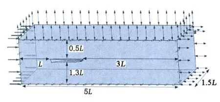
Fig.6 Computational domain of the model
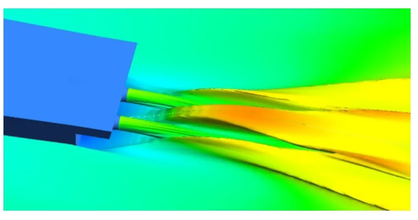
Fig.7 Wash wave of the ship
The result of the steady field is initial value for calculating the transient unsteady field,the DES turbulence model is adopted in this paper;the back pressure of the nozzle is zero;the wall of the duct is no slip wall;the boundary conditions for the duct inlet is the velocity inlet,which is the same as the boundary conditions of the ‘hull+duct+waterjet’and the time of the every calculation step equal to the time of impeller rotates 3 degrees.When the impeller rotates 3~5 periods later,the value of the monitoring points changes periodically,the pressure pulse of the Waterjet pump is exported at the next periods as the excitation source of calculating the sound field.As shown in Fig.9,eight monitor points are set in the Waterjet pump’s X=0 section,including the 1~4 points at the impeller inlet and the 5~8 points at the interaction area of the impeller and stator[10].When the periodic phenomenon of the unsteady field calculation is stable,the pressure value of the monitor points are exported during the last 2 cycles.In order to obtain the spectral characteristics of the fluctuating pressure,the pulse pressure is transformed from time domain into frequency domain through the fast-Fourier transform(FFT).Fig.10 is the graph of pressure fluctuation in frequency domain,where the abscissa represents the multiple shaft frequency.Due to the Waterjet pump with 7 blades,rotating speed is 1 440.5 rpm,so the shaft frequency is 24 Hz,the blade frequency is 168 Hz.
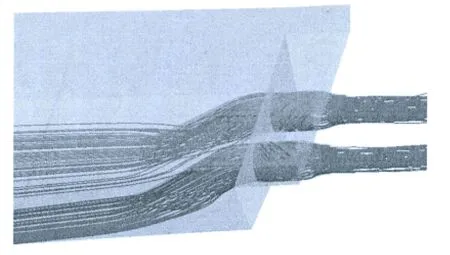
Fig.8 Flow streams in the pump
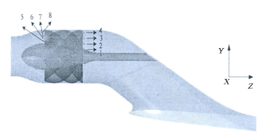
Fig.9 Position of the monitor points
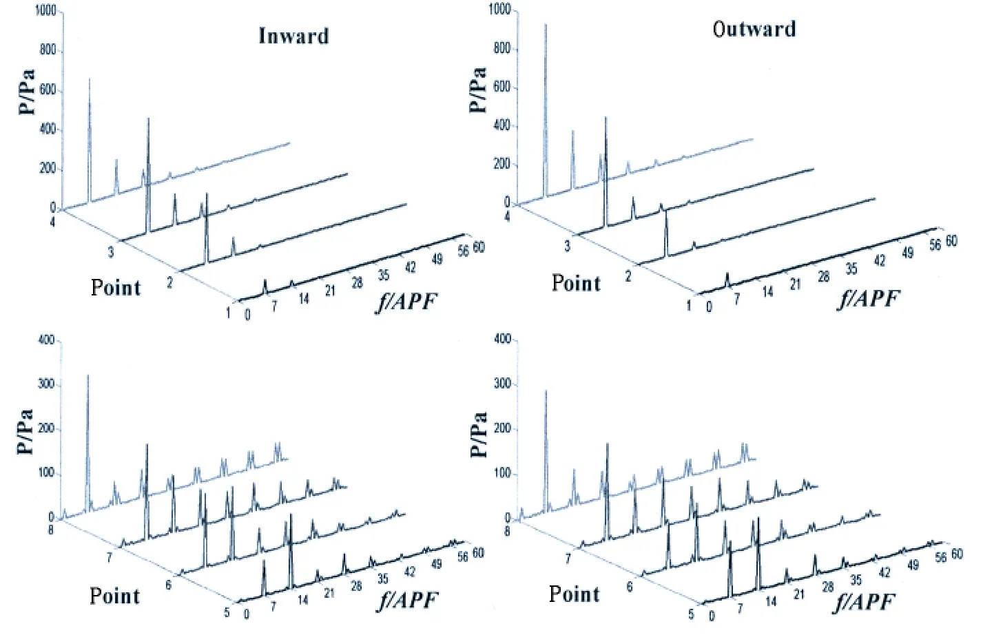
Fig.10 Pressure fluctuation of the monitor points
The main frequency of the pulse pressure of the impeller and stator interaction area and the impeller inlet is 7 times the blade frequency,which is fit in with the blade passing frequency of the impeller blade and the blades sweep process is the main reason of pressure pulsation.The amplitude of the pressure pulsation increases from the hub to shroud,and the amplitude of the pressure pulsation of the outward is larger than the inward in the impeller inlet area,but in the interaction of the impeller and stator,the amplitude of pressure pulsation of the inward is larger than in the outward.
4 Calculation of the noise of waterjet pump
4.1 Method of calculating the sound field
When the boundary element method is used to calculate the under-water radiated noise of the waterjet;firstly,the acoustic source distribution of the solid wall of the Waterjet pump should be calculated;secondly,the boundary element method is used to calculate the sound pressure distribution of the acoustic source from the waterjet pump to the impeller inlet area(including sound real and imaginary);the process is shown in Fig.11.When the sound field is calculated,the result of transient calculation by CFD is employed as boundary condition by introducing the Green function,and an arbitrary point pressure is calculated by:
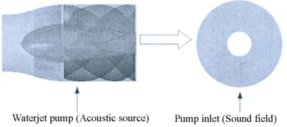
Fig.11 Calculating the radiation noise of waterjet

where Pais frequency sound pressure of the observation,is the velocity vector,→is the observation point coordinate vector,→is the sound source coordinate vector, ω is the sound frequency.G represents the Green function,which satisfies the equation:

On the solid surface,G should satisfies the equation:

4.2 Building the BEM model
The model of acoustic boundary element is built up,namely meshing the solid boundary.In order to meet the requirement of engineering calculation,a wavelength should include 6 meshes.Due to the maximum of calculation frequency has been known,so maximum length of the mesh should satisfy:

where l is the maximum length of the mesh unit,c is the speed of sound in a fluid medium,fmaxis the maximum frequency.The speed of sound in the water is 1 500 m/s,the maximum frequency is 1 000 Hz,so the maximum length of the acoustic mesh is 1.5 mm.Eventually,the number of the elements is 30 142,the number of the nodes is 29 628 in the waterjet pump and the number of the elements is 1 524,and the number of the nodes is 1 563 in the impeller inlet.Acoustic mesh as shown in Fig.12.
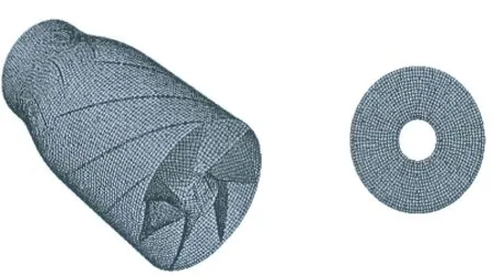
Fig.12 Acoustic mesh of waterjet pump and inlet
4.3 Calculation and analysis of the radiated noise
The main mechanism of the waterjet’s radiated noise is the pressure difference between the impeller blade back and leaf(usually called load noise)and load noise can be equivalent to a dipoles source.When the boundary element method is used to calculate the under-water radiated noise of the waterjet;the acoustic source distribution of the solid wall of the waterjet pump should be calculated;secondly,the boundary element method is used to calculate the sound pressure distribution of the waterjet pump and impeller inlet,as show in Figs.13-16.The main sound source is located at the interaction of the impeller and stator,the impeller blade tip leakage vortex region,the leading edge of the impeller and stator and the shroud of the impeller inlet area.
Due to the interaction of the impeller and stator,in the interaction area,the distribution of the sound source is stronger,and the amplitude is larger no matter the low frequency or high frequency,which is main noise source determining the level of the total noise frequency;the impeller inlet section presents seven regular high pressure area,this phenomenon disappear at a relatively high frequency and the high pressure area of the impeller inlet is close to the interaction area of the blade and shroud.
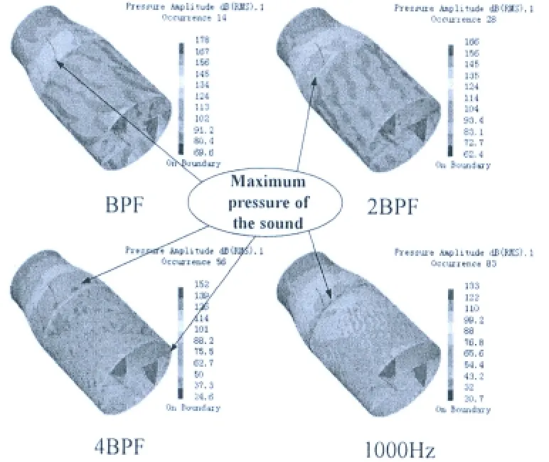
Fig.13 Acoustic strength distribution of the inward pump
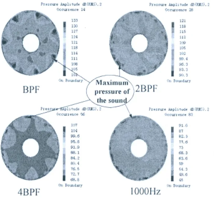
Fig.14 Acoustic strength distribution of the inward pump inlet

Fig.15 Acoustic strength distribution of the outward pump
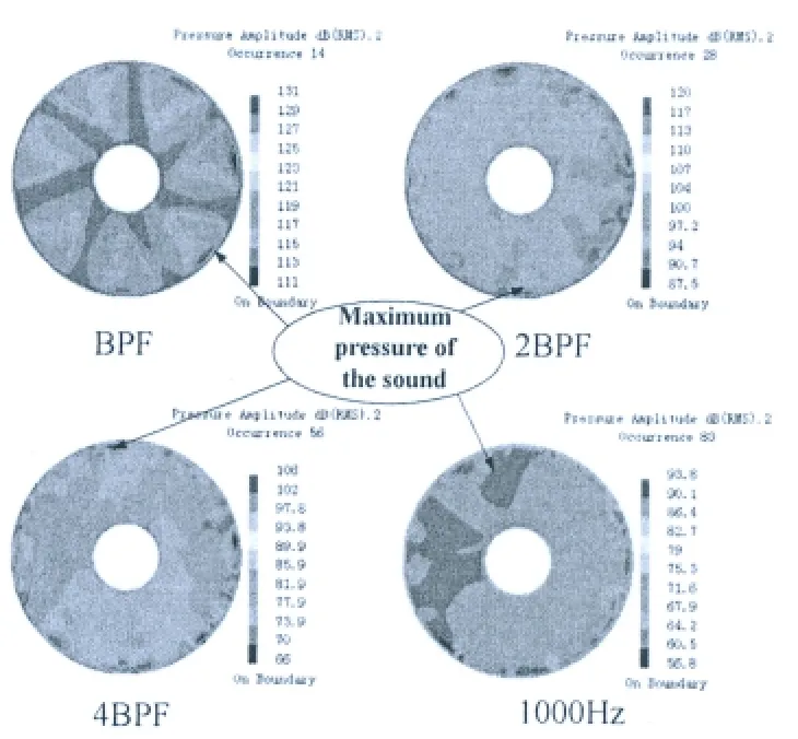
Fig.16 Acoustic strength distribution of the outward pump inlet
In order to obtain the average sound pressure level of the impeller inlet area,the sound pressure distribution of the impeller inlet area is done for the average energy,the reference pressure of the average energy is 1×10⁻⁶Pa;getting the sound pressure spectrum level curve of the impeller inlet in the 1 000 Hz,as shown in Fig.17,which shows an obvious peak vale in the BPF,2BPF,3BPF,4BPF and 5BPF,but obvious excursion appears near the 3BPF and 4BPF;the blade frequency is more obvious and good regularity.According to the formula of total sound pressure level:
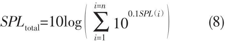
where SPL()
iis the third-octave center frequency point of sound pressure level.So the total sound pressure level of the impeller inlet area in 1 000 Hz,the inward pump is 142.6 dB and the outward pump is 140.2 dB.Due to the non-uniform flow of the stern waterjet ship and impeller’s interaction,so that the total sound pressure level of the inward pump is 2.4 dB larger than that of the outward.
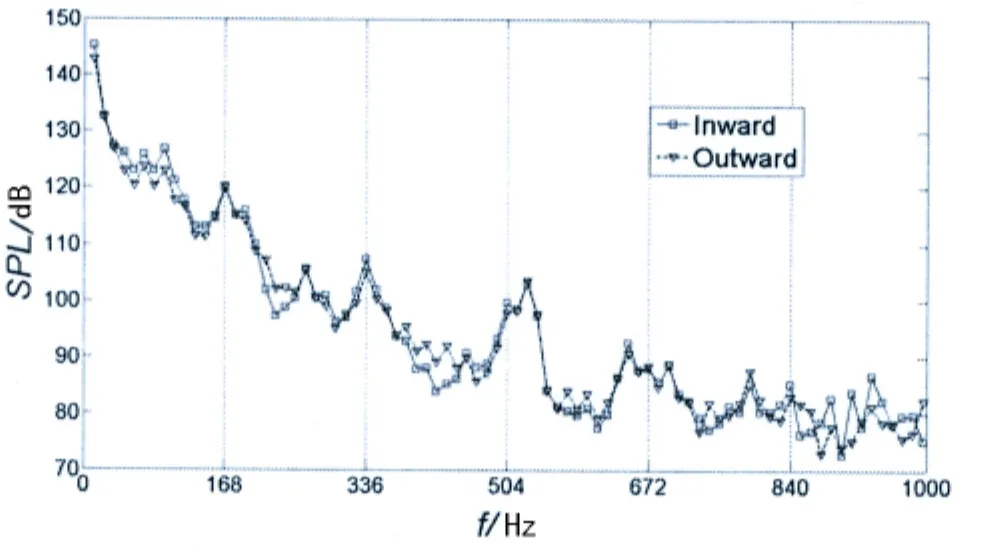
Fig.17 Acoustic pressure spectrum line of the pump inlet
5 Conclusions
Computational fluid dynamic(CFD)and direct boundary element method(DBEM)are used to calculate the influence of rotation direction of impeller on noise performance of waterjet.The double waterjet propulsion ship is analyzed,from which the dipoles of the impeller,stator,hub and the shell are obtained,the radiated noise of the waterjet pump can be obtained through the direct boundary element method(DBEM):
(1)The main frequency of the pulse pressure of the waterjet pump interior is the blade passing frequency,which appears in the area of the impeller inlet,the amplitude of the pressure pulsation increases from hub to the shroud,the amplitude of the pressure pulsation of the outward waterjet is larger than that of the inward one in the impeller inlet area,but in the interaction of the impeller and stator the pressure pulsation of the inward waterjet is larger than that of the outward one.
(2)Through DBEM analysis in 10~1 000 Hz,the interaction region of the impeller and stator is the main contribution to radiation noise,what is more,the total sound pressure level of the inward pump is 2.4 dB larger than that of the outward one.
[1]Magnus Källman,Li Daqing.Waterjet propulsion noise[C]//Waterjet Propulsion III,20 and 21 February 2001:Gotherburg,Sweden,2001.
[2]Dong R,Chu S,Katz J.Effect of modification to tongue and impeller geometry on unsteady flow,pressure fluctuations and noise in a centrifugal pump[J].ASME Journal of Fluids Engineering,1997,119:506-515.
[3]Reese H,Carolus T.Axial fan noise:Towards sound prediction based on numerical unsteady flow data-a case study[C].Acoustics 08 Paris,June29-July4,2008.
[4]Timouchev S,Tourrel J.Numical simulation of BPF pressure pulsation field in centrifugal pump[C].Proceedings of the 19th International Pump Users Symposium,2002:85-105.
[5]Langthjem M,Olhoff N.A numerical study of flow-induced noise in a two-dimensional centrifugal pump.Part I:Hydrodynamics[J].Journal of Fluids and Structures,2004,19:349-368.
[6]Langthjem M,Olhoff N.A numerical study of flow-induced noise in a two-dimensional centrifugal pump.Part II:Hydroacoustics[J].Journal of Fluids and Structures,2004,19:369-386.
[7]Mou Jiegang,Li Shihuang,Wang Leqin.Noise and noise reduction mechanism analysis of waterjet[J].China Mechanical Engineering,2003,14(18):1558-1561.
[8]Chang Shuping,Wang Yongsheng.Prediction of waterjet performances using k-ε turbulence models[J].Journal of Huazhong University of Sience and Technology(Nature Sience Edition),2012,4:88-90.
[9]Yi Wenbin.Research on waterjet/hull interaction,duct’s design and stern selection of submerged waterjet[D].Wuhan:Naval University of Engineering,2013:27-39.
[10]Jin Shuanbao,Wang Yongsheng,Chang Shuping,Su Yongsheng.Pressure fluctuation of interior flow in mixed-flow pump[J].Transactions of the Chinese Society for Agricultural Machinery,2013,44(3):64-68.
- 船舶力学的其它文章
- 《船舶力学》稿约须知
- 总目次(2014年)
- A Review of Short-term Prediction Techniques for Ship Motions in Seaway
- Cabin Noise Control on Large Oil Tankers
- Research on the Design of Hull Crashworthiness Structure based on Sandwich Plate System
- Influence of Stress Wave on Dynamics Damage Character of Ship-build Low-carbon Steel Based on Low-velocity Taylor Impact Bar