
Analysis of hydrodynamic characteristics of unmanned underwater vehicle moving close to the sea bottom
2014-03-09 11:57:08XioxuDUHunWANGChengzhiHAOXinlingLISchoolofMrineSciencendTechnologyNorthwesternPolytechniclUniversityXi710072ChinKunmingReserchInstituteofPrecisionMchineryKunming650118Chin
Defence Technology 2014年1期
Xio-xu DU*,Hun WANGCheng-zhi HAO,Xin-ling LISchool of Mrine Science nd Technology,Northwestern Polytechnicl University,Xi’n 710072,Chin Kunming Reserch Institute of Precision Mchinery,Kunming 650118,Chin
1.Introduction
Deep-sea exploration sometimes needs unmanned underwater vehicle(UUV)sailing close to sea bottom[1].It has been found that a submarine sailing close to the sea bottom can effectively reduce the probability of being detected[2].All sorts of coupling flows,which have signi fi cant in fluence on the hydrodynamics,appear in the surrounding area of UUV and the sea bottom due to the boundary effect of sea bottom[3].The coupling flows may affect the security and stability of working,therefore,a research about the hydrodynamic characteristics of UUV moving close to the sea bottom seems particularly necessary.
At present,the research on underwater sailing near the sea bottom is comparatively rare.Bystron and Anderson(1998)made a model test,and concluded that the vertical force and trimming moment show linear features obviously with the dimensionless change of distance between the hull and the sea bottom[4].Kuang Xiao-feng studied the attraction characteristics of submarine sailing close to the sea bottom[3].Zhu Xin-yao studied the hydrodynamic characteristics of UUV parking on the seabed[5].Zhu Ai-jun carried out experimental study about the relationship between the drag of underwater vehicles and the distance to the sea bottom[6].In the above literature,no comprehensive analysis of UUV moving close to sea bottom was made,and the model test lacked theoretical veri fi cation.In this paper,the hydrodynamic characteristics of UUV close to the sea bottom were studied,which we believe has signi fi cance on manipulation of UUV near the sea bottom.
Currently,there are mainly three methods to calculate hydrodynamic parameters,including empirical formula,model test and numerical simulation[7].Empirical formula method is simple and quick,but it can’t re fl ect the difference among various models,so its calculation accuracy is not high.Model test costs too much and has a long cycle,so it is usually limited by budget and schedule.The numerical simulation method is mature,in particular,development of some large commercial simulation software makes the computational fl uid dynamics(CFD)method more and more widely used[5].The numerical simulation method needs lesser time and lower cost for a new design compared to the experimental study.It is advantageous for the optimized design and has the advantages of easy-tocontrol and good repeatability.In many cases,the numerical simulationcanreachthesameaccuracyasthatofmodeltest[8].
In order to study the hydrodynamic characteristics of UUV moving close to the sea bottom,in this paper,the structured grid of the computational model is generated by Ansys ICEM.Then numerical simulation was carried out by CFX,and the relationship among drag,lift,pitching moment features and the distance to sea bottom,attack angle was studied.
2.Mathematical model
Tosolveviscous flowproblemsistosolvetheNavier-Stokes equations.In this paper,the Reynolds-averaged Navier-Stokes(RANS)equations and the shear stress transport(SST)model,namely RANS equation method,are used.The SST turbulence modelisintroducedtoconstituteaclosedequationforobtaining the turbulence elements in means[9].
2.1.Basic control equation
For steady incompressible flow,the control equations include equation of continuity and equation of motion.
Equation of Continuity[10]

Equation of Motion(N-S Equation)[11]

where U is the velocity vector,ρ is the mass density of water,p is the pressure,g is the acceleration of gravity,and μ is the fl uid dynamic viscosity coefficient.
2.2 SST k-ω model
Shear stress transport model(short for SST k-ω model)combined the advantages of the k-ω model and the k-ε model,which make it have a wider application.SST k-ω model has the following advantages:1)This model can adapt various physical phenomenon where pressure gradient changes;2)It is applicable to viscous layer,and it can precisely simulate the phenomenon of boundary layer through the application of the near-wall function without using the viscous damping function which may distort easily.During calculating,the solving procedure can call different turbulence models automatically according to the size of the Reynolds number.Namely,it uses k-ω model at low Reynolds number region and the k-ε model at high Reynolds number region[12].Therefore,SST k-ω model has good adaptability in dealing with boundary layer problem with different Reynolds numbers.So we choose SST k-ω model as the turbulence model.
2.3.Near-wall treatment
As mentioned,the turbulence model which aimed at fully developed turbulence is established.It is effective under the condition of high Reynolds number while near the solid wall,the Reynolds number turns smaller because of the molecular viscosity,which engenders turbulent flow pulsation damping.As a result,the laminar flow is presented near the wall where turbulence development is not suf ficient.Typically we use a series of semi-empirical formula to combine the variables on the wall with the corresponding physical quantities of central area,instead of directly solving the problem in view of the apparently viscous area.That is the wall function method[13].
The method for near-wall consists of the standard wall function method and the enhanced wall method.The latter one is aimed at small gap flow or low viscosity and high velocity flow,where the physical measurement changes rapidly.A high quality grid is required and the first node near the wall should be located in the viscous sub-layer,which means y+≈1[14].
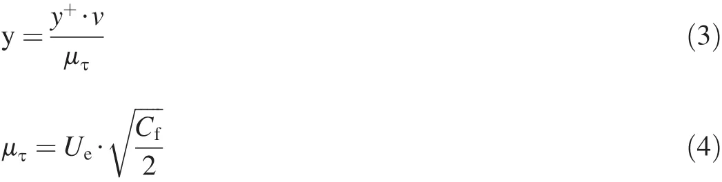
where y is the height of the first layer grid,Ueis the velocity vector,Cfis the resistance coefficient.
In this paper,we use the standard wall function method which has high computational ef ficiency and strong practicability.By adjusting the height of boundary layer gird,y+can be controlled between 30 and 60 in order to improve the accuracy of numerical calculation[15].
3.Calculation model,working condition and grid generation
3.1.Calculation model
For numerical study on flow field around the UUV,a calculation domain is typically formed by constructing virtual boundary,and the RANS equations within the domain are solved.Therefore,a boundary condition needs to be given for the spatial domain.In this paper,the hexahedral calculation domain is used for simulation,as shown in Fig.1.
The UUV which we studied has a length of 1850 mm,and its biggest diameter is 200 mm.The size of the calculation domain is 7.4 m×4 m×4 m.The distance between the head of UUV and velocity inlet(Fig.1)is 1.85 m,and the distance between tail and pressure outlet(Fig.1)is 3.7 m.The distance between the axis of UUV and the sea bottom is adjusted to represent the change of the distance between UUVand the sea bottom.
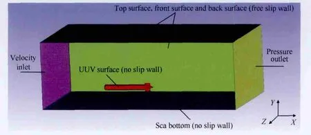
Fig.1.Calculation model of UUV moving close to sea bottom.
3.2.Working condition
The hydrodynamic characteristics of UUV moving close to sea bottom at 2 kn-5 kn is mainly studied here.The working conditions of UUV are listed in Table 1.The relationship among drag,lift,pitching moment,distance to sea bottom,and attack angle is studied.
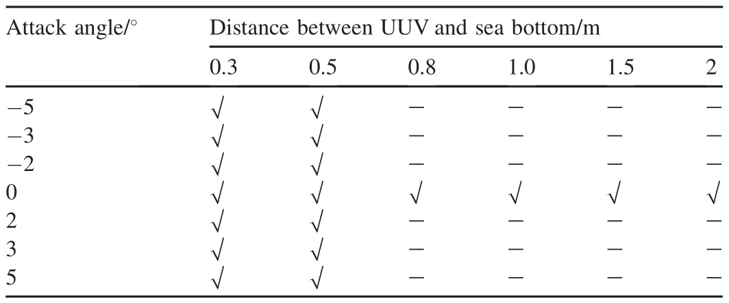
Table 1 UUV working conditions(v=2 kn,v=5 kn).
3.3.Grid generation
The quality of grid directly affects the convergence,accuracy and feasibility of numerical simulation.Structured grid is easy to adjust its density,and has less memory demand.It has advantage of solving the problem about boundary layer.It can improve the accuracy and credibility of results for the numerical simulation[12].So the hexahedral structured grid is used in this paper.
In this paper,SST k-ω model is used as the turbulence model,and the demand of grid is same as standard wall function.After calculation,0.4 mm is taken as the height of the first layer grid,the growth rate is 1.2.Finally,the whole domain are divided into 2.3 million meshes.The grid quality reaches more than 0.5,and the minimum distortion angle is 22°,it is a higher quality.Fig.2 shows the grid of UUV surrounding area when the distance between UUV and sea bottom is 1 m and the attack angle is-5°.
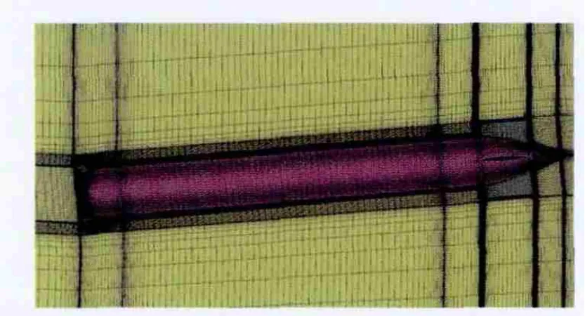
Fig.2.Grid of UUV surrounding area.
4.Calculation results and analysis
4.1.Grid independence test
In general,mesh density level largely affects the calculated error.Weneedtogetapropernumberofthegridthroughthegrid independence test.With the increase of the number of grid,the result changes in a range of allowable error,that is when we get the proper number[16].
The grid independence test is performed using the 1.8 millions,2.3 millions and 3.15 millions grid number for case when the distance is 1 m,the attack angle is 0°and the velocity is 5 kn.The drag,lift and pitching moment coefficients are treated as the validation parameters.The whole numerical calculation can be finished in a quad-core,4 g memory con fi guration,as illustrated in Table 2.
The value under condition of 2.3 millions grid number is treated as reference value,the errors of the other two cases are presented in Table 2.In the case of 1.8 millions grid number,the error is slightly larger and it may have the consequences of instability for the calculation of other conditions.In the case of 3.15 millions grid number,it needs a larger computer memory and calculation time,so it is not appropriate for the calculation of large numbers of conditions because it costs too much.In the case of 2.3 millions grid number,an appropriate computer memory is needed,and it has a satisfactory accuracy.As a result,the grid number of 2.3 millions is selected as the number of grid.

Table 2 The grid independence test results.
4.2.Drag characteristics
In order to increase the universality of the conclusion,the distance(h)between UUV and the sea bottom is transformed into nondimensional parameter e,e=h/D,where D is the biggest diameter of UUV.
4.2.1.In fluence of the distance
Fig.3 shows the relation between the drag coefficient Cxand e at two kinds of velocity.
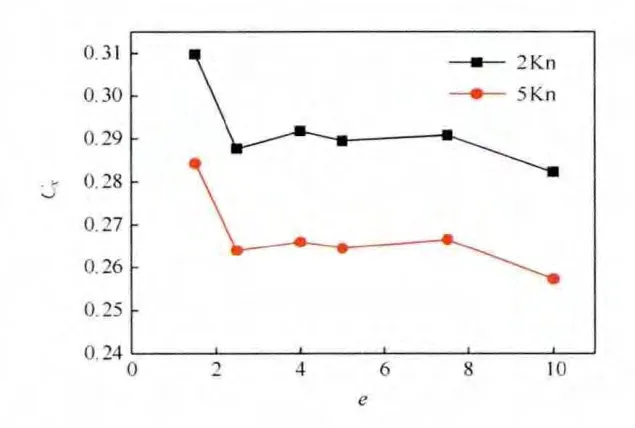
Fig.3.Relation between Cxand e.
Generally,the drag of UUV can be divided into two parts,pressure force and viscous force[17].
It is shown in Fig.3 that the sea bottom has a larger effect on drag coefficient for e≤2.5.Normally the drag coefficient increases obviously with the decrease in e.The reason is that the pressure force increases obviously while the viscous force changes little with the decrease in e.For example,when U=5 kn,e=2.5,Fv=12.5 N,Fp=15.5 N(where Fvis the viscous force,Fpisthe pressure force),while U=5 kn,e=1.5,Fv=12.0N,Fp=18.2N.When e>2.5,thechange of e affects less on drag coefficient.
4.2.2.In fluence of attack angle
Fig.4 shows the relation between the drag coefficient Cxand the attack angle α when UUV moves at 5 kn.
It can be seen from Fig.4 that the drag coefficient is related to the attack angle,When the attack angle is 0°,the minimum drag coefficient is gotten.The reason is that the area,which faces to the flow,increases when the UUV sails with an attack angle.As a result,the viscous force and the pressure force increase.We can also found that the drag coefficients under the condition of positive and negative attack angles are also different,because of the existence of fin and rudder.
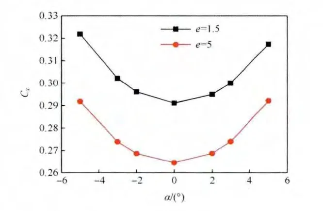
Fig.4.Relation between Cxand α.
4.3.Lift characteristics
4.3.1.In fluence of distance
In this paper,the vertical upward direction is de fined as the positive direction.Fig.5 shows the relation between the lift coefficient Cyand e at two kinds of velocity.

Fig.5.Relation between Cyand e.
It can be seen from Fig.5 that there exists attraction force from the sea bottom for e<5,and the attraction force increases rapidly with the decrease in e.The reason can be found in the velocity contour(Fig.6).The velocity distribution on the surface of UUV is not symmetrical any more due to the in fluence of the sea bottom,the velocity is higher on the lower surface.Then it can be concluded by Bernoulli equation that the pressure on lower surface decreases,and even is smaller than that at its corresponding location on the upward surface.This creates a result that UUV is subjected to a resultant force in the vertical direction,and the closer the distance from the sea bottom is,the bigger the attraction force is.
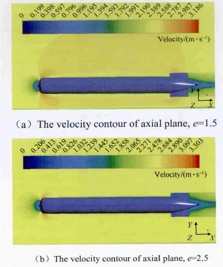
Fig.6.The velocity contours of axial plane,U=5 kn,α =0°.
4.3.2.In fluence of attack angle
Fig.7 shows the relation between the lift coefficient Cyand the attack angle α when UUV moves at 5 kn.
It can be seen from Fig.7 that the lift coefficient increases with the increase in attack angle.When α =0°,UUV is under the in fluence of attraction from sea bottom,so UUV is recommended to sail at a small positive attack angle in order to overcome the attraction.Then it can get away from the danger of touching with the bottom.On the other hand,if UUV sails at a negative attack angle,the attraction increases.It is not advantaged to the safe navigation.
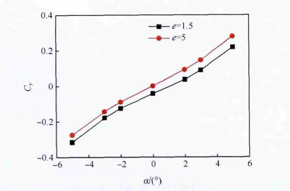
Fig.7.Relation between Cyand α.
4.4.Pitching moment characteristics
4.4.1.In fluence of distance
Fig.8 shows the relation between the pitching moment coefficient Cmzand e at two kinds of velocity.
It can be seen from Fig.8 that the variation law of pitching moment coefficient is similar to lift coefficient.The velocity contour(Fig.6)can still provide a good explanation for the variation law of pitching moment coefficient.Because the attraction force doesn’t concentrate on the centroid,the pitching moment of UUV will be produced,and the absolute value of pitching moment coefficient increases with the decrease in e.
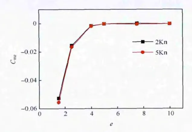
Fig.8.Relation between Cmzand e.
4.4.2.In fluence of attack angle
Fig.9 shows the relation between the pitching moment coefficient Cmzand attack angle α when the UUV moves at 5 kn.
It can be seen from Fig.9 that the pitching moment coefficient increases gradually with the increase in attack angle.The reason is that the existence of attack angle makes a certain angle be between the surface of UUV and the flow.Flow impact on its vertical surface increases,leading to the increase of the pitching moment.
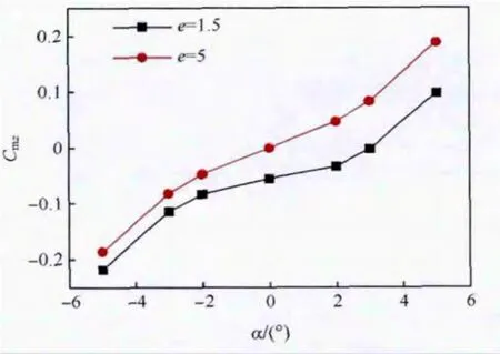
Fig.9.Relation between Cmzand α
5.Conclusions
In this paper,the mathematical model of UUV moving close to sea bottom was established based on the incompressible viscous flow.The structured grid of the computational models at different distances from the sea bottom and different attack angles was generated by Ansys ICEM.Then the numerical simulation of flow field near sea bottom was carried out by CFX,and the following conclusions were drawn through the numerical simulation.
1)For e≤2.5,the pressure force increases with the decrease in the distance from sea bottom,which causes the increase in drag coefficient.For e>2.5,the effect of the sea bottom can be ignored,and the maneuverability of UUV cannot be in fluenced.In addition,the drag coefficient increases with the increase in attack angle.
2)For e≤5,the existence of the sea bottom makes the pressure distribution of UUVunsymmetrical any more,the attraction force from the sea bottom is formed,and the attraction force increases with the decrease in e.Therefore,an additional manipulation and control scheme is required when UUV moves close to the sea bottom.Because the lift coefficient increases with the increase in attack angle,we suggest that UUV keeps a certain positive attack angle when it moves close to the sea bottom.
3)Because the attraction force doesn’t concentrate on the centroid,the pitching moment of UUV will be produced.According to the simulation result,the absolute value of pitching moment coefficient increases with the decrease in e,and increases with the increase in attack angle.
Acknowledgment
This research was sponsored by National Natural Science Foundation of China(11302176)and Research Fund for the DoctoralProgram ofHigherEducation ofChina(20126102120021)
[1]Yoerger Dana R,Jakuba Michael,Bradley Albert M.Techniques for deep sea near bottom survey using an autonomous underwater vehicle.Robotics ResearchIn Springer Tracts in Advanced Robotics,vol.28;2007.pp.416-29.
[2]Lin CY,Zhu J.Numerical computation of added mass of submarine maneuveringwithsmallclearancetosea-bottom.ShipEng2003;25(1):26-9[in Chinese].
[3]Kuang XF,Miao QM,Cheng MD.Hydrodynamic numerical study of submarine near the sea bottom.In:The ship hydrodynamic Conference Proceedings;2004.pp.140-5[in Chinese].
[4]Bystron L,Anderson R.The submarine underwater maneuvering.submarine technology research and development.In:The 5th International Conference on Submarines Selection.China Ship Scienti fi c Research Center;2000.pp.132-43.
[5]Zhu XY,Song BW,Wang P.Hydrodynamic characteristics analysis of UUV parking on seabed.Introd J China Ordnance 2012;33(8):934-43[in Chinese].
[6]Zhu AJ,Ying LM,Zheng H.Resistance test method on underwater vessel operatingclosetothebottomorthesurface.JShipMech2012;16(4):368-74[in Chinese].
[7]Zhang HX,Pan YC.Application CFD to compare submarine hull forms.J Ship Mech 2006;10(4):1-8[in Chinese].
[8]Wu JG,Chen CY,Wang SX.Hydrodynamic characteristics of wings of hybrid-driven underwater glider in glide mode.J Tianjin Univ 2010;43(1):84-9[in Chinese].
[9]Hu ZQ,Ling Y,Gu HT.On numerical computation of viscous hydrodynamics of unmanned underwater vehicle.Robot 2007;29(2):145-50[in Chinese].
[10]Jing SR,Zhang MY.Fluid mechanics.Xi’an:Xi’an Jiaotong University Press;2001[in Chinese].
[11]Anderson Jr John D.Computational fl uid dynamics.USA:McGraw-Hill Companies;1995.
[12]PanG,ShiY,DuXX.Numericalsimulationofsink-stabilityforunmanner underwater lurk vehicle.J Shanghai Jiaot Univ 2012;46(9):1493-7[in Chinese].
[13]Ji BB,Chen JP.ANSYS ICEM CFD detailed examples of meshing technology.Beijing:China:Water and Power Press;2012[in Chinese].
[14]Chen L.Hydrodynamic interactions between two bodies.Harbin:Harbin Engineering University;2006[in Chinese].
[15]ANSYS Inc.Document for ANSYS ICEM CFD 14.5.USA:ANSYS Inc;2012.
[16]Zhao PF.CFD prediction of open water and cavitation characteristic of marine propelle.Dalian:Dalian University of Technology;2011[in Chinese].
[17]Pan G,Du XX,Song BW.Torpedo mechanics.Xi’an:Shaanxi Normal University Publishing House Limited;2013[in Chinese].
- Defence Technology的其它文章
- Estimation of the kinetic parameters for thermal decomposition of HNIW and its adiabatic time-to-explosion by Kooij formula
- Effect of welding processes and consumables on fatigue crack growth behaviour of armour grade quenched and tempered steel joints
- Research on design and firing performance of Si-based detonator
- Dynamic globularization prediction during cogging process of large size TC11 titanium alloy billet with lamellar structure
- A numerical study on the disturbance of explosive reactive armors to jet penetration
- Biased retro-proportional navigation law for interception of high-speed targets with angular constraint