A numerical study on the disturbance of explosive reactive armors to jet penetration
Xiang-dong LI*,Yan-shi YANG,Sheng-tao LV
School of Mechanical Engineering,Nanjing University of Science and Technology,Nanjing 210094,China
1.Introduction
Explosive reactive armors(ERA)have been widely used as add-on-armors against shaped charge jets and long rod armor piercing projectiles.The disturbance of explosive reactive armors on jet penetration was studied in this paper.Most ERA has a sandwich con fi guration consisting of a front plate,an interlayer explosive,and a rear plate.When the interlayer explosive is penetrated by a shaped-charge jet,it explodes,accelerating the front and rear plates to move outwards in their normal directions.The moving plates and detonation products interact continuously with the jet,signi fi cantly disturbing its motion.The jet may bend,break and scatter around its original axis,resulting in a signi fi cant reduction in the penetration into the primary target behind the reactive armor[1].To increase its disturbance on the jet,which frequently strikes the target at various impact angles,V-shaped sandwich reactive armors were introduced.In a V-shaped con fi guration,two sets of fl at ERAs,consisting of its own front plate,high interlayer explosive and rear plate,are placed at a speci fi c angle[2].
A number of experimental and analytical studies have been made to investigate the disturbance mechanism of reactive armors on jet penetration.With the aid of X-ray photography,Wu and Huang measured the plate velocity of ERA detonated by a jet[3,4].Mayseless,Rototaev and Liu established the theoretical models which could predict the disturbance effect of ERA[5-8],respectively.Murr and Held have studied the effects of the thicknesses of sandwich plate and interlayer explosive on the ef ficiency of ERA[9,10].Held also investigated the in fluences of the boundary effect of an ERA[11]and the distance between ERA and the main target on the ef ficiency of ERA[12].Held found out that the reduction effect in penetration remains also more or less constant in the case of hitting the top or the bottom,where only the front and rear plates interact with the jets,in vertical directions.
Numerical approaches have been applied for simulations of high speed impact events,including the formation and penetration of shaped charge jets,for more than forty years[13].With the advance of computer technologies,several commercial hydrocodes are available for the study of the shaped-charge jet formation and penetration into various types of targets[14].Shin and Lee numerically studied the detonation behaviour of double reactive cassettes by impacts of projectiles with various nose shapes[15].Ismail[16]investigated the interaction of shaped charge jet with ERA using the AUDODYN hydrocode,and the result showed that inclination NATO angle[9]and the striking point are critical parameters.These studies demonstrated that various projectile/ERA parameters can be investigated ef ficiently,and the predictions could be compared with experimental results for better understanding of the complex phenomenon/mechanisms involved.
This paper presents a numerical study on the penetration process of a jet into an ERA with the focus on the disturbance effect of ERA on the jet.With the same set of geometry parameters and material constants,the jet formation and the disturbance interactions between the jet and the ERA target were successfully simulated using the finite element code LSDYNA[14].Numerical results of normal penetrations are compared with experimental results.The predicted plate velocities of both fl at and V-shaped ERAs are in agreement with X-ray photographic measurements.The predicted penetration depth of a steel target without ERA is close to the test results.The models which has been veri fi ed by test are then employed to study the penetration of the jet into both fl at and V-shaped ERA con fi gurations.Based on the numerically predicted results,the in fluences of the impact angle and V-shaped angle on jet performance are discussed.
2.Numerical and material models
2.1.Numerical model
The numerical model consists of a shaped-charge,a liner,an ERA,and a main target.The investigated reactive armor includes fl at and V-shaped con fi gurations.The fl at reactive armor is constructed of the front plate,rear plate and interlayer explosive,while the V-shaped con fi guration consists of two fl at reactive armor units at a particular angle.The two confi gurations are shown in Fig.1.
The shaped-charge is 56 mm in diameter and 73 mm in height.The liner(copper)is 54 mm in caliber diameter and 1 mm in thickness.The cone angle of the liner top is 60°,and the stand-off distance from the bottom of the shaped-charge to the ERA front plate is 80 mm.The thicknesses of front plate,interlayer explosive and rear plate of the sandwich layer are 3 mm,2 mm and 1 mm,respectively.
The axis-symmetric modeling techniques are used in the numerical simulations because of the structural symmetry of model.The jet formation and penetration process is a large deformation process,therefore Eulerian element formulation is employed for the liner,explosive and air.While for ERA sandwich plates and the main target,Lagrangian element formulation is used to ensure the stability of the numerical process[14].It is noted that non-re fl ection contact condition is adopted for the shaped-charge explosive/air interface.
2.2.Material models and properties
2.2.1.Liner
The responses of liner material at different pressure levels are described by both the Steinberg material model and the Gruneisen equation of state.
The Steinberg model,which accounts for the combined effects of pressure,temperature and plastic ductility,is suitable for large deformation situations at high strain rate.In this model,the shear modulus G and the yield stress σyincrease with the increase in pressure while decrease with the temperature[14,17].Both G and σyapproach to zero when the material melts.G is expressed by

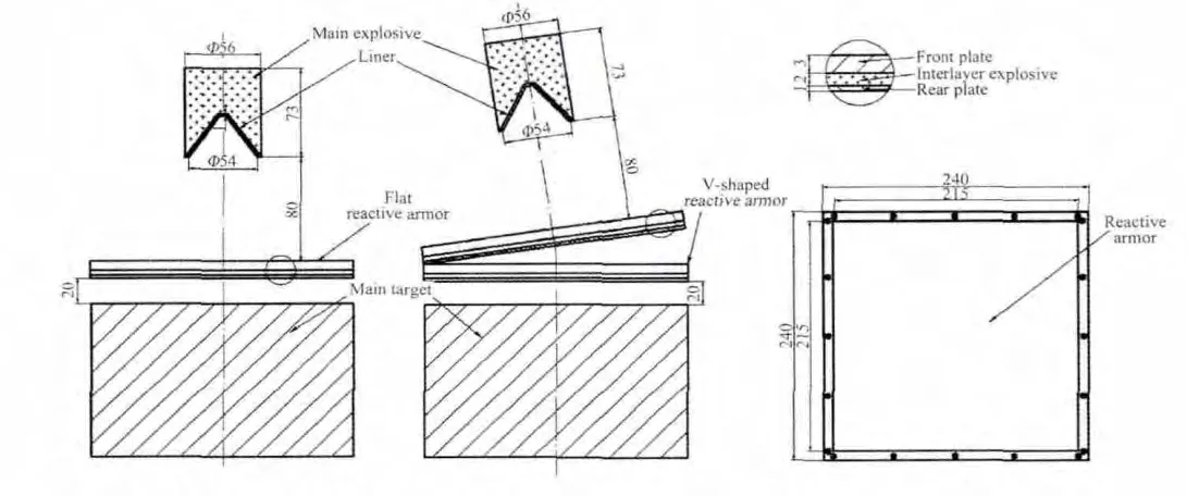
Fig.1.The shaped charge,liner,ERA and main target.

where G0,b,,,h,and f are material constants determined by experiment;p is pressure;V is relative volume;Ecis cold compression energy;Emis melting energy;Eiis speci fi c internal energy;R′=Rρ/A,R is the gas constant,ρ-density,and A-the Mole mass.
The Gruneisen equation of state expresses the pressure of compressible materials as

where ρ0is density of material;E is internal energy of initial unit volume material;C is interception at the vertical axis of the shock velocity versus particle velocity(us-up)curve;S1,S2,S3are the coefficients that determine the shape of us-upcurve;γ0is Gruneisen gamma;and a is the first order volume correction toγ0.
In addition,the relative volume μ=1/V-1 describes the compression status.The particle velocity upis related to the shock velocity usby

The pressure of the expanded material is described by

Table 1 lists the material constants of copper used in this investigation.
2.2.2.Metallic plates of ERA and main target
The materials of front and rear plates of the sandwich ERA,and the main target plate are described by the Johnson-Cook model[14].John-Cook’s formulation of the flow stress is expressed by
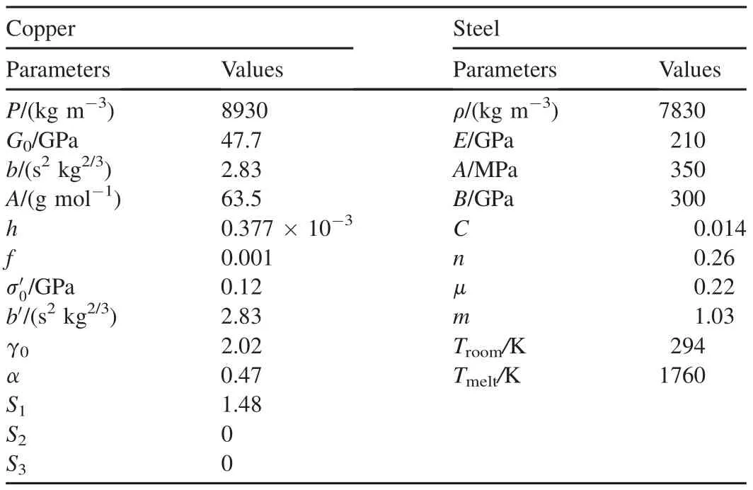
Table 1 Material constants of the liner and steel.

where A,B,C,n and M are mapterial constants;εpis the effective plastic strain;andε˙*=ε˙/ε˙0is the effective plastic strain rate,ε˙0=1s-1;and is the relative temperature given by T*=(T-Troom)/(Tmelt-Troom).
The strain at fracture is given by

where D1,D2,D3,D4and D5are material constants;σ*=σpis the ratio of pressure d1ivided by the von-Mises equivalent stress,σ=[(3/2)sijsij]2.Note that sijis the deviator stress tensor.
Fracture occurs when the damage parameter[14]D=reaches the value of 1.
The materials of the sandwich plates and the main target are 45#steel.The material property constants described in Eqs.(6)and(7)are listed in Table 1.In addition,the values of D1,D2,D3,D4and D5are taken from Ref.[18].
2.2.3.Shaped-charge explosive
The shaped-charge explosive is RDX-8701,which is described by the“Mat_High_Explosive_Burn”material option in DYNA and the JWL equation of state.The explosive burning equation describes the explosive behavior before its detonation,and controls the release of chemical energy for simulating detonation.The JWL equation describes the pressure,volume and energy of the reaction product in the process of detonation,it de fines the pressure as[14]

where A,B,R1,R2and ω are material constants;E is the initial internal energy;and V is the relative volume.Material constants in Eq.(8)are listed in Table 2,in which the detonation speed of explosive is also provided.
2.2.4.Interlayer explosive of ERA
The “ignition-and-growth-of-reaction-in-HE”equation of state is used for the interlayer explosive.This model is suitable to calculate the shock initiation and detonation wave propagation of solid high explosives.At a relatively low initial pressure(<2-3 GPa),the equation of state is used to calculate the behavior of the un-reacted high explosive with the material type 10 of DYNA[14].
The equation of state de fines the pressure in the un-reacted explosive as

and de fines the pressure in the reaction products as

where r3= ωecvr and g= ωpcvp;r1,r2,r3,r5and r6are calibration constants;Veand Vpare the relative volume of the un-reacted and detonation product,respectively;Teand Tpare the temperature of the un-reacted explosive and the detonation product,respectively.
As the chemical reaction converts un-reacted explosive to reaction products,these equations of state are used to calculate the mixture of un-reacted explosive and reaction products de fined by the fraction F(F=0 implies no reaction,F=1 implies complete reaction).The temperatures and pressures are assumed to be equal(Te=Tp,Pe=Pp),and the relative volumes are additive[14],i.e.,
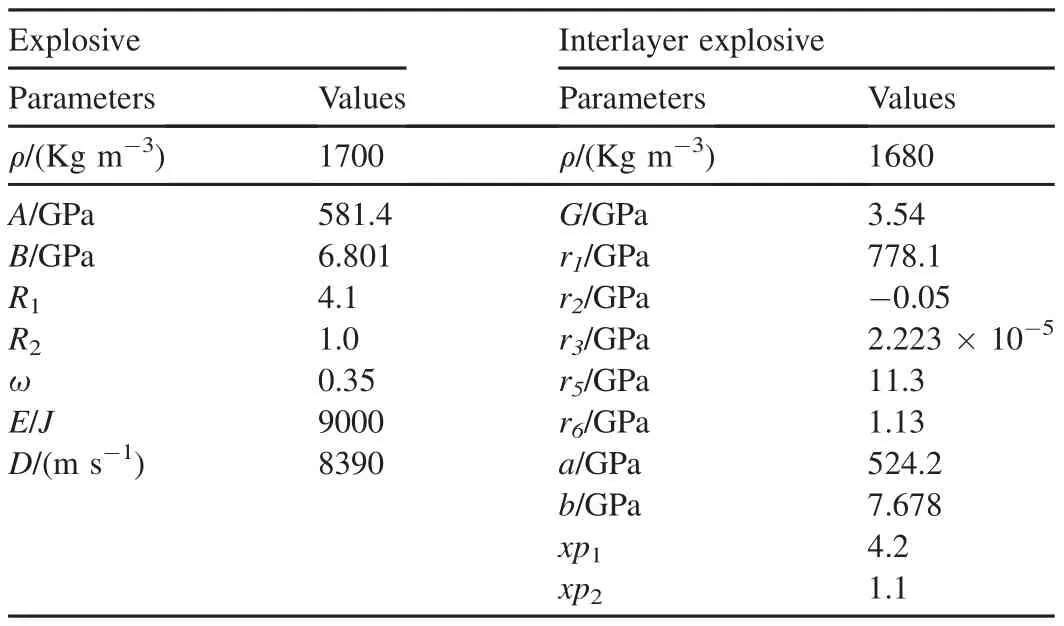
Table 2 Explosive material constants of the ERA and shaped-charge.

Material constants described in Eqs.(9)and(10)are also listed in Table 2.
3.Simulation of jet formation and motion of sandwich plates
The penetration depth of the jet into the steel main target and the motion of the front and rear plates were predicted to study the disturbance mechanism of ERA on the jet.
3.1.Jet formation and penetration capability
The formation of the jet and its normal penetration into steel target without ERA are first analyzed and compared with available experimental results to verify the proposed approach.Fig.2 shows the distribution of the jet velocity along its axis(26 μs after charge detonation)and the geometrical shape of jet predicted.The velocity of jet tip is 6500 m/s,and the diameter of the tip is 4 mm.When the jet hits the target,its tip velocity is 6520 m/s.The penetration depth is 241.2 mm for a normalpenetration into asteeltarget(withoutERA).Compared with the test results[4,18]of 220 mm,it is seen that the present numerical prediction is close to the test results.
3.2.Motion of sandwich plates
A number of jet/ERA tests were performed to validate the numerical simulation results using shaped charge,liner,ERA,and target con fi gurations and parameters similar to those of the numerical model.The velocities of the front and rear plates after the reactive armor detonation were measured.An experiment set-up is shown in Fig.3.The reactive armor is detonated by normal penetration jet with respect to the main target.Fig.3(a)shows the fl at ERA con fi guration,and Fig.3(b)shows the V-shaped ERA con fi guration.Two fl ash X-ray tubes are arranged to get two X-ray images at different times,which can be used evaluated the velocity of the plates[4].
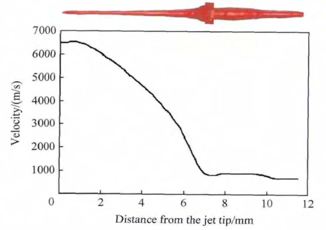
Fig.2.Velocity pro fi le and shape of jet.
X-ray and numerical simulation images of detonation reactive armors(by jet)at the time of 60 μs and 130 μs are shown in Fig.4 and Fig.5,respectively.As shown in the fi gures,after the reactive armor is initiated by the jet impact,the reaction product expands rapidly,which drive the front and rear plates move along their normal directions.
Table 3 summarizes the average velocities of the reactive armor plates measured by the test and predicted by the numerical simulations.It is observed that a fairly good agreement between the experimental and numerical results is obtained.
4.Disturbance of fl at ERA
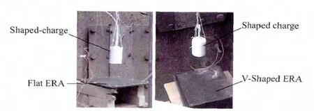
Fig.3.Measurement setup for plate velocity of ERA.
The jet penetration into the fl at ERA and the main target at impact angles of 0°,40°,50°,55°,60°,and 68°are simulated to identify how the fl at ERA disturbs the penetration behavior of jet.For the cases with and without fl at ERA,the penetration depth versus with impact angle is contrasted.
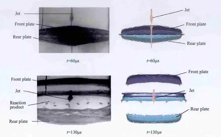
Fig.4.X-ray image and numerical results of fl at ERA.
4.1.Normal penetration
Fig.6 shows the numerical simulation results of the fl at ERA penetrated by jet.The reaction product drives the front and rear plates to move along opposite directions,as shown in Fig.6.The reaction product scatters symmetrically along the jet’s path.The front and rear plates move parallel along the direction of the jet’s path.Therefore,in this case,the transverse disturbance of the front and rear plates to the jet is quite limited.The residual penetration depth of the jet into the main target is 219.4 mm,and the penetration capability of jet reduced by 9.1%because of reactive armor protection.As the same with the Held’s research result,the disturbance of ERA to jet penetration is not very distinct in the vertical direction.
4.2.Oblique penetration
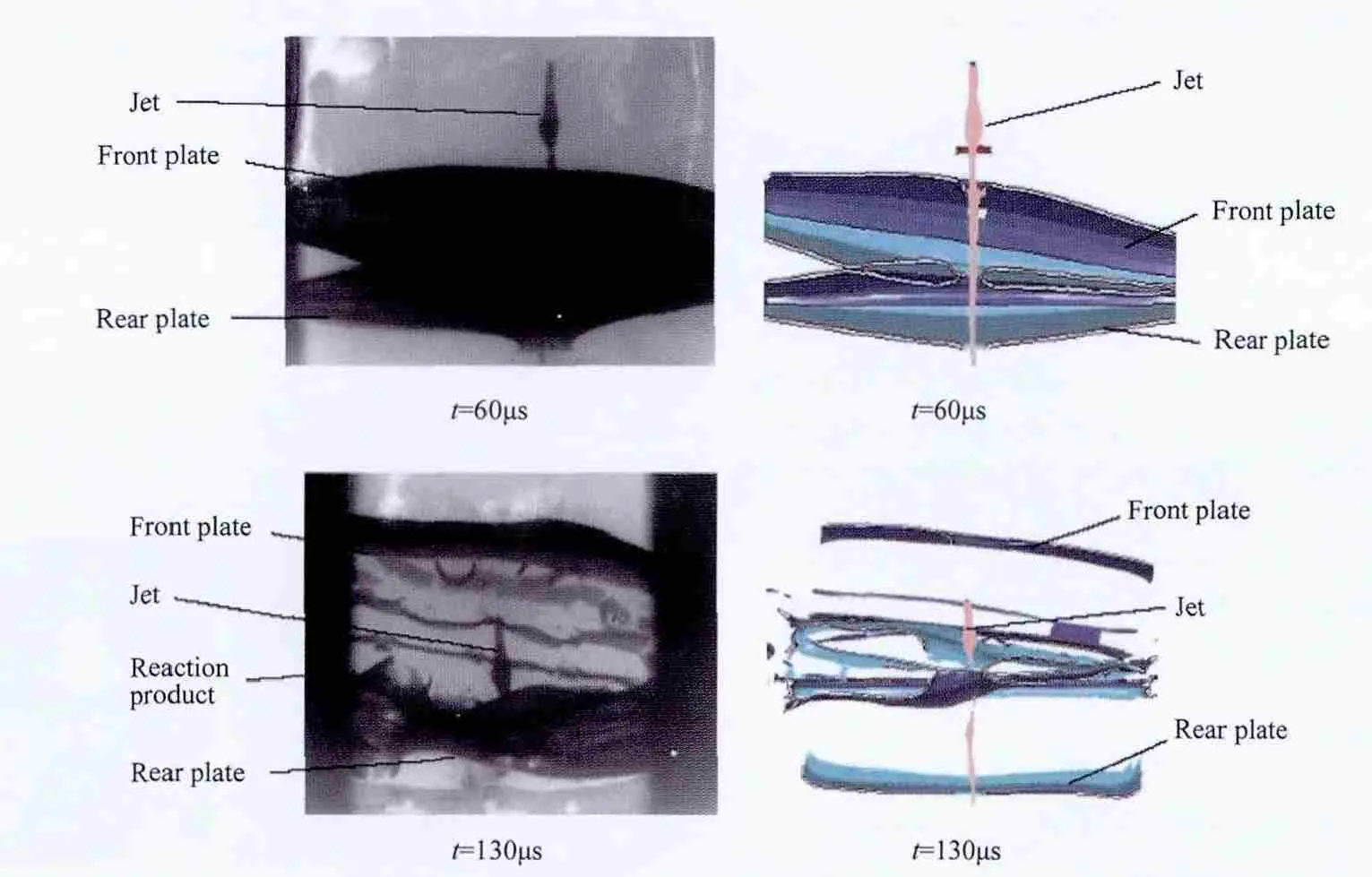
Fig.5.X-ray image and numerical results of V-shaped ERA.
The typical interaction patterns of the jet penetrating into ERA and main target at an impact angle of 68°are shown in Fig.7.Compared with the normal penetration shown in Fig.6,the reactive armor disturbs the jet more signi fi cantly during oblique impact.When the explosive of ERA is detonated,the outward movements of the plates cut the jet directly,thus severely disturbing the penetration process.With the formation of more jet segments as a result of the continuous interaction,the residual penetration capability is reduced signi fi cantly.It can be seen from Fig.7 that,when the disturbed jet penetrate into the plate at a larger impact angle,its tip slides along the surface of the rear plate,resulting in bending,breaking,and scattering the jet(segments).Thus the depth of penetration into the main target is signi fi cantly reduced.

Table 3 Experimental results and numerical predictions.
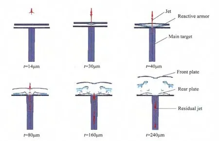
Fig.6.Predicted results of demonstrated penetration process(normal impact).
For the case of a jet penetrating into the fl at ERA,Fig.8 shows the penetrations of jet into main target at various impact angles.It is observed that the larger the impact angle is,the severer the disturbance of ERA to jet is,and the more the reduction of the penetration depth into the main target is.
It can also be seen from Fig.8 that the slant penetration path of the jet in the main target is further de fl ected with the increase in impact angle,which is caused by the bend of jet.The diameter of the penetration hole,especially at the entrance,also becomes larger with the increase in impact angle because of the scattering of the jet segments.
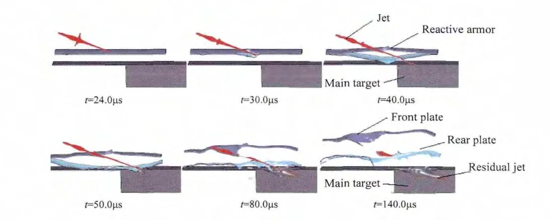
Fig.7.Predicted results of demonstrated penetration process(impact angle of 68°).

Fig.8.Simulated penetration holes of jet at different impact angles.
Fig.9 shows the predicted main target penetrations for the cases with and without fl at ERA at different impact angles.The penetration is measured normal to the surface of target.So in the case of that without fl at ERA,the penetration depth of main target is

where L0is the length of crater;and α is the impact angle.
It can be seen from Fig.9 that the greater the impact angle is,the shallower the penetration depth is.In addition,the penetration depth is reduced signi fi cantly when the impact angle is more than 45°.The penetration depth is reduced by 55%-75%in the range from 45°to 68°(impact angle)with respect to case without ERA.
5.Disturbance of V-shaped ERA
The process of jets penetrate into V-shaped ERA at the impact angles of 45°,50°,55°,60°and 68°are computed in order to investigate the effects of the impact angle and V-angle on the residual penetration depth.In the following subsections,the numerical results of the jet penetrating into 9°V-angled sandwich ERA at various impact angles and the results of penetration at 60°impact angle with V-angles of 0°,5°,9°,13°,17°and 21°are presented.
5.1.Oblique penetration
Fig.10 shows the penetration process for a V-angle of 9°and an impact angle of 60°.The entire penetration process can be qualitatively described.After the jet tip hits the reactive armor,it makes the interlayer explosive detonate.The reaction product drives the front and rear plates of the ERA upper unit to move outward in their normal directions,and then the interlayer explosive of the ERA lower unit is detonated due to the co-action of the jet and the detonation pressure and the rear plate of the upper unit.Detonated upper and lower elements of V-shaped con fi guration disturb the jet greatly.The jet bends,de fl ects and forms more broken segments,resulting in a larger entrance area on the target and reducing the penetration depth signi fi cantly.It is obvious that the protective ability of the V-shaped ERA is much better.Compared with the penetration of jet into the main target,the ability of jet penetration is greatly weakened.
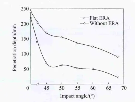
Fig.9.Penetration depths at different impact angles.
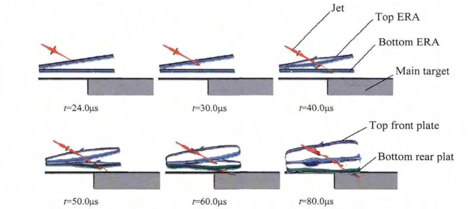
Fig.10.Predicted results of demonstrated penetration process(impact angle of 60°).
5.2.In fluence of impact angle
Fig.11 shows the predicted results of main target penetration for the cases with and without 9°V-shaped ERA at various impact angles.It can be seen from Fig.11 that the penetration capability is reduced by 60%-90%for the range of impact angles studied.Fig.12 shows the penetration holes of the disturbed jet penetrating into the main target.It is shown that the penetration path is deviated,and the de fl ection increases with the increase in impact angle.The diameter of the hole,especially at the entrance,becomes larger with the increase in impact angle.Similar to the case of fl at ERA described in Section 4.2,the former and the latter are probably caused by the bend of jet and the decentralization of jet,respectively.
5.3.Effect of V-angle
Fig.13 shows the predicted main target penetration at 60°fi xed impact angle for the cases without ERA and with V-shaped ERAs with various V-angles.For the case without ERA,the curve in Fig.13 is a straight line and represents the results of penetration at 60°impact angle.For the case with ERA,the penetration depth dose not vary monotonically with the increase in V-angle.In the process of jet penetration,the front and rear plates of ERA fl y away in the opposite direction.When the angle of V-shaped sandwich reactive armor con fi guration is small,there isn’t enough space for the rear plate to move,and the jet penetrates vertically into the main target with the increase in angle,the penetration depth increases.As the angle reaches a certain value,there is enough space for the rear plate to rotate and move,meanwhile the jet is greatly disturbed by the rear plate,which reduces the depth of penetration.It can be seen from Fig.13 that the maximum point is at a V-angle of about 13°.However,the variation of penetration depth with increase of V-angle is quite small.It is observed that the penetration depth is reduced by 85%-90%for all the studied V-angles.Therefore it is demonstrated that the reduction of the penetration depth is not sensitive to V-angles investigated in this paper.
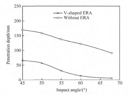
Fig.11.Comparison of the penetration results at different impact angles(V-angle of 9°).
6.Conclusions
The following conclusions are drawn from the present numerical study on the jet penetration into homogeneous target with and without reactive add-on armors.
1)The proposed approach successfully simulated the significant disturbance and cutting effects of the moving front and rear plates on the jet.In addition,the parametric studies were performed to quantify the reduction of the penetration depth due to the jet bending,breaking,and jet(segment)scattering in the various conditions of jet/ERA/target.
2)For fl at ERA con fi guration,no signi fi cant bending and cutting effects were observed for the normal impact,thus the disturbance of fl at reactive armor to jet penetration was not considerable.However,it was observed that,for

Fig.12.Simulated penetration holes at different impact angles.
oblique impact,the penetration depth was reduced by 55%~75%.
3)For V-shaped ERA con fi guration,the impact angle had a great effect on the reduction of the penetration.However,for various V-angles and at a fi xed impact angle,the reduction of penetration depth was not sensitive to V-angles studied.
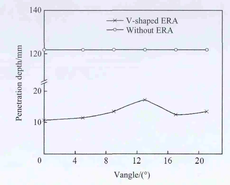
Fig.13.Comparison of the penetration results at different V-angles(impact angle of 60°).
[1]Held M,Mayseless M,Rototaev E.Explosive reactive armor.In:Proceedings of the 17th International Symposium on Ballistic.Midrand,South Africa;1998.pp.33-46.
[2]HazellPJ.Advancesin explosive reactive armor.MilTechnol 2008;6:124-33.
[3]Wu C,Jiang J.A study on the moving features of explosive reactive armor by numerical simulation and experiments.Acta Armamentarii 2002;23(1):35-8.
[4]Huang Z,Li G,Chen H.Numerical simulation and experimental study on double explosive reactive armor. J Ballist 2005;17(4):40-3.
[5]Mayseless M,Marmor E,Gov N,Kivity Y,Falcovitz J,Tzu D.In:Interaction of a shaped charge jet with reactive or passive cassettes.Proceedings of the 14th International Symposium on Ballistics.Quebec,Canada,vol.11;1993.pp.439-48.
[6]Murr LE,Staudhammer KP,Meyers MA.Modeling and simulation of interaction process of shaped charge jet and explosive reactive armor.In:Metallurgical and materials Applications of shock-wave and high-Starin-rate Phenomena.Proceedings of the 1995 International Conference on Metallurgical and materials Applications of shockwave and high-strain-rate Phenomena(EXPLOMET ’95);1995.pp.511-8.
[7]Liu H,Zhao G.Study on jet break up in explosive reactive armor(ERA)by normal penetration.Mech Eng 2007;29(4):63-6.
[8]Zeng F,Li J.A further study of the disturbance mechanism on jets caused by reactive armors.J Beijing Inst Technol 1994;14:286-91.
[9]Held M.Stopping power of ERA sandwiches as a function of explosive layerthicknessorplate velocities.Propellants,ExplosPyrotech 2006;31(3):234-8.
[10]Held M.Dynamic plate thickness of ERA sandwiches against shaped charge jets.Propellants,Explos Pyrotech 2004;29(4):244-6.
[11]Held M.Edge effects on ERA sandwiches.Propellants,Explos Pyrotech 2006;31(2):98-101.
[12]Held M.Effectiveness of an ERA-sandwich with a large distance between sandwich and target. Propellants, Explos Pyrotech 2001;26(1):33-7.
[13]Zukas JA.Introduction to hydrocodes.Studies in applied Mechanics 49.Elsevier;2004.
[14]Livermore Software Technology Corporation.LS-DYNA keyword user’s manual.Version 970.Livermore;2003.pp.2042-63.1316-1319.
[15]Shin Hyunho,Lee Woong.A numerical study on the detonation behaviour of double reactive cassettes by impacts of projectiles with different nose shapes.Int J Impact Eng 2003;28(4):349-62.
[16]Ismail MM,Rayad AM,Alwany H,Alshenawy TA.Optimization of performance of explosive reactive armors.In:Proceedings of the 21st International Symposium on Ballistics.Adelaide,Australia,vol.1;2004.pp.227-32.
[17]Toda S,Kibe S.Analysis of jet formation and penetration by conicalshaped charge with the Inhibitor.IntJ ImpactEng 1999;23(1):443-54.
[18]Dong X.Study on the disturbance mechanism of jets caused by reactive armors.Master degree thesis.Nanjing:Nanjing University of Science and Technology;2008.
- Defence Technology的其它文章
- Effect of welding processes and consumables on fatigue crack growth behaviour of armour grade quenched and tempered steel joints
- Estimation of the kinetic parameters for thermal decomposition of HNIW and its adiabatic time-to-explosion by Kooij formula
- Research on design and firing performance of Si-based detonator
- In fluence of yttrium on microstructure and properties of Ni-Al alloy coatings prepared by laser cladding
- Biased retro-proportional navigation law for interception of high-speed targets with angular constraint
- Dynamic globularization prediction during cogging process of large size TC11 titanium alloy billet with lamellar structure

