Effect of welding processes and consumables on fatigue crack growth behaviour of armour grade quenched and tempered steel joints
G.MAGUDEESWARAN*,V.BALASUBRAMANIAN,G.MADHUSUDHAN REDDYDepartment of Mehanil Engineering,PSNA College of Engineering&Tehnology,Kothandaraman Nagar,Muthanampatti,624622 Tamilnadu,India Centre for Materials Joining&Researh,Department of Manufaturing Engineering,Annamalai University,Annamalai Nagar,608002 Tamil Nadu,India Metal Joining Group,Solidi fi tion Tehnology Division,Defene Metallurgil Researh Laoratory,Kanhanagh,Hyderaad 500058,India
1.Introduction
Quenched and Tempered(Q&T)steels are used in military applications due to high hardness,high strength to weight ratio and excellent toughness[1].These grades of Q&T steels are prone to hydrogen induced cracking after welding and they exhibit heat affected zone softening leading to poor ballistic performance[2].Austenitic stainless steel(ASS)welding consumables are being used for welding Q&T steels,as they have higher solubility for hydrogen in austenitic phase,to avoid hydrogen induced cracking(HIC)[3].But use of stainless steel fi llers for a non stainless steel base metal must be avoided as ASS fi llers are much more expensive.Recent studies proved that low hydrogen ferritic steel(LHF)consumables can be used to weld Q&T steels,which can give very low hydrogen levels in the weld deposits[4-6].Q&T steel welds must be of good quality especially when used for construction of combat vehicles in military applications.The majority of armour fabrication is performed by fusion welding process and they demand for highest welding quality.Shielded metal arc welding(SMAW)and the fl ux cored arc welding(FCAW)processes are widely used in fabrication of combat vehicle construction[7,8].
Due to the heterogeneity induced from welding,base metal(BM),weld metal(WM)and heat affected zone(HAZ)have different mechanical behaviours,which makes welded joints complicated under local stress-strain conditions[9].For structural steels,the strength of the welded joints determines the strength of the whole structure.Welded joints are subjected to various forms of cyclic loading in practical applications and fatigue failure is common.Thus,welding is a major factor in the fatigue lifetime reduction of components[10].Failure analysis of the weldments indicated that fatigue alone is to be considered to account for most of the disruptive failures.Even though the fatigue properties of the weld metal is good,problems can be caused when there is an abrupt change in section caused by excess weld reinforcement,undercut,slag inclusion and lack of penetration and nearly 70%of fatigue cracking occurs in the welded joints[11].As the fatigue failure is one of the prime concerns in structural design and the butt weld is a part of many structures,its evaluation and prediction of fatigue life is very important to avoid catastrophic failure particularly in steels that are used in military applications.Thus,it is always important to enhance the service life of the structural components under cyclic loading conditions by choosing proper welding process,consumables,etc.Apart from the mechanical considerations of joint design,the welding process, fi ller material,heat input,number of weld passes etc.,will in fluence the microstructure of the weld at the joint and in turn will in fluence the extent of heat affected zone and residual stresses that will build up in the base metal.These factors will invariably affect the fatigue strength by increasing the propensity for crack nucleation and its early growth causing the ultimate failure of the joint[12,13].The use of ASS&LHF consumables and SMAW&FCAW welding processes for armour grade Q&T steel will lead to formation of distinct microstructures in their respective welds.This microstructural heterogeneity will have a drastic in fluence in their fatigue crack growth properties of the respective welds.Considering all the above facts,an investigation was carried out to evaluate the fatigue crack growth properties of armour grade Q&T steels fabricated by SMAW(manual)and FCAW(semi-automatic)processes using ASS and LHF welding consumables.The present study assumes signi fi cance as fatigue crack growth studies have not been reported in this class of armour grade Q&T steel welds fabricated by SMAW and FCAW processes using ASS and LHF consumables.
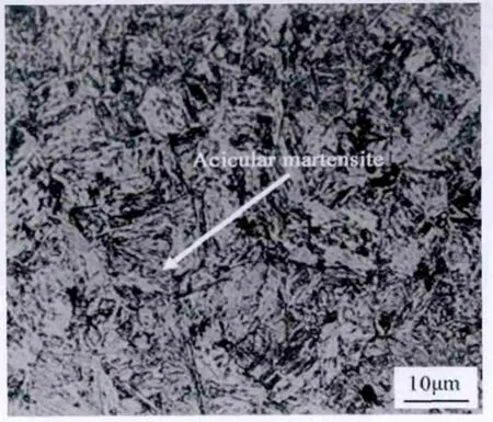
Fig.1.Microstructure of the base metal.
2.Experimental work
2.1.Joint fabrication
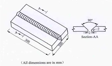
Fig.2.Joint con fi guration.
The base metal used in this investigation is a Q&T steel,closely con fi rming to AISI 4340 speci fi cation.The microstructural feature of the base metal exhibits acicular martensite(Fig.1).Rolled plates of 14 mm thick base metal were sliced into the required dimensions(300 mm×100 mm)by abrasive cutters and grinding.Single ‘V’butt joint con fi guration,as shown in Fig.2,was prepared to fabricate the joints by SMAW and FCAW processes.The initial joint con fi guration was obtained by securing the plates in position using tack welding.The direction of welding was normal to the rolling direction.All necessary care was taken to avoid joint distortion and the joints were made after clamping the plates in a welding fi xture.Austenitic stainless steel(ASS)and low hydrogen ferritic steel(LHF)consumables were used to fabricate the joints.The joints fabricated using ASS consumables are referred as SA and FA joint and the joints fabricated using LHF consumables are referred as SF and FF joint respectively by SMAW and FCAW processes.The chemical composition of the base metal and weld metals were determined using vacuum spectrometer(Model:Spectrolab)and are presented in Table 1.The process parameters used to fabricate the joints are given in Table 2.The welding procedures(process parameters)followed in this investigation was carried out as per guidelines given in the report[14]for welding of armour grade Q&T steel used for combat vehicle construction.A detailed weldability test on the armour grade Q&T steel using the fi ller metals and procedures mentioned in this investigation has been carried out by the authors and has been reported[6].From this study,it is understood,that the level of diffusible hydrogen content in all the electrodes(ASS,and LHF)is very much lower than the actual permissible level.The welds made using the above consumables were offering superior resistance against hydrogen induced cold cracking if they are fabricated with proper preheat temperature,interpass temperature,electrode baking temperature,etc.,as mentioned in Table 2.No evidence of delayed cracking after welding was found in all the welds fabricated using the above welding consumables and welding procedures[6]and the same has been adopted for welding in this investigation also.The welded joints were sliced and then machined to the required dimensions(as shown in Figs.3 and 4)for preparing various test specimens used in this investigation.

Table 1 Chemical composition of(%wt)of base metal and fi ller metals.
2.2.Fatigue crack growth testing
Centre crack tension(CCT)specimens were prepared to the dimensions as shown in Fig.3.The slices derived from the welded joints were reduced to a thickness of 10 mm by shaping and grinding processes to obtain fl at and required surface roughness.Then the sharp notch was machined in weld metal region to provide ai/W length using the wire cut electric-discharge machine(EDM).Procedures prescribed by the ASTM E 647-05 standard were followed for the preparation of the specimens.Fatigue crack growth experiments were conducted using a servohydraulic controlled(Make:INSTRON 8801),100 kN capacity fatigue testing machine with a frequency of 20 Hz and a stress ratio of 0.01(R=0.01).
Fatigue crack growth experiments were carried out at three different stress levels(100,150 and 200 MPa)and at each stress levels three specimens were tested.Before loading,the specimen surface was polished using metallographic procedures and illuminated suitably to enable the crack growth measurement.A travelling microscope(Make:MITUTOYA)with a video output was used to monitor the crack growth with an accuracy of 0.01 mm.The fatigue testing machine and the experimental set up is shown in the following section.After the specimen was gripped between the upper and lower gripping arrangement,cyclic load was applied on the specimen.
The initial 0.5 mm increment of crack length(2a)from the tip of the machined notch and corresponding number of cycles was recorded as crack initiation life(Ni)as per the crack“Initiation Criteria”.The subsequent crack propagation at each 1 mm interval and corresponding number of cycles was recorded until complete failure of the specimen.The data points measured with an accuracy of 0.01 mm were fi tted with a smooth curve crack length vs number of cycles(a vs N).At any chosen value of the crack length,two points lying on either side of the chosen point and very close to each other were fi xed and the length ‘da’was measured accurately.The corresponding number of cycles to make the crack propagate through this distance of ‘da’has been was determined so that the slope da/dN at the chosen value of the crack length ‘a’can be determined.In a similar manner,the crack growth rate,da/dN,at different chosen values of the crack length ‘a’and the corresponding applied cyclic stress were determined.ASTM standard E-647-05 guidelines were followed for all the cases to evaluate crack growth rate,da/dN.
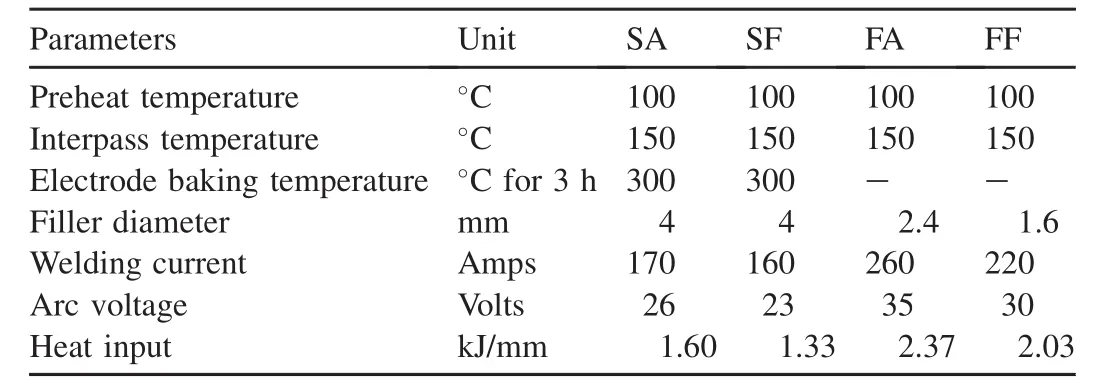
Table 2 Welding conditions.
2.3.Transverse tensile testingµhardness
Tensile specimens have been prepared as per ASTM E8M-04 speci fi cations as shown in Fig.4 to evaluate yield strength,tensile strength and joint ef ficiency in accordance with the ANSI/AWS B4.0-98 guidelines for mechanical testing of welds.Tensile test has been carried out in 100 kN,electromechanical controlled Universal Testing Machine Make:FIE-Blue Star,India;Model:94100.Vicker’s microhardness testing machine(Make:Shimadzu;Model HMV-T1)was used for measuring the hardness across the weld and in the heat affected zone regions.
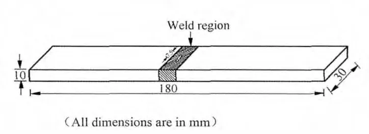
Fig.3.Centre crack tension fatigue crack growth test specimen.

Fig.4.Transverse tensile specimen.
2.4.Microstructure
The microstructure analysis of the weldments was carried out using a light optical microscope(Make:MEIJI,Japan;Model:ML7100).The Specimens were etched with 2%Nital reagent to reveal the microstructure of the weld region of low hydrogen ferritic joint,heat affected zone(HAZ)of all the joints and base metal(BM).Aquaregia was used to reveal the microstructure of the austenitic stainless steel weld metal regions.
2.5.Residual stress
To analyse the in fluence of residual stresses on fatigue crack growth behaviour of the base metal and the welded joints,the residual stress was measured in the as ground condition at the crack tip of the CCT specimens(before fatigue testing)by using X-ray stress analyzer(Make:Stresstech OY,Finland;Model:XStress 3000).
2.6.Fractography
The fractured surface of the test specimen were analysed using SEM(Make:JEOL and Model:5610LV)at high magni fi cation to study the fracture morphology and to establish the nature of the fracture.Before examining under SEM,the specimens were cleaned ultrasonically with carbon tetrachloride and acetone.
3.Results
3.1.Fatigue crack growth
Centre crack tension(CCT)specimens were used to evaluate fatigue crack growth behaviour of welded joints.The fatigue crack growth experiments were conducted at three different stress levels(Δσ)of 100,150 and 200 MPa and all the experiments were conducted under constant amplitude loading conditions(R=0.01).
The measured variations in crack length(2a)with the corresponding number of cycles(N)are plotted as shown in Fig.5a.All joints were tested in the as welded condition and the notch was located in the weld metal region.From the graphs,it can be observed that the base metal exhibits higher fatigue crack growth resistance than the welded joints.However,the crack growth is relatively slower in SF joints compared to other joints considered in this investigation.
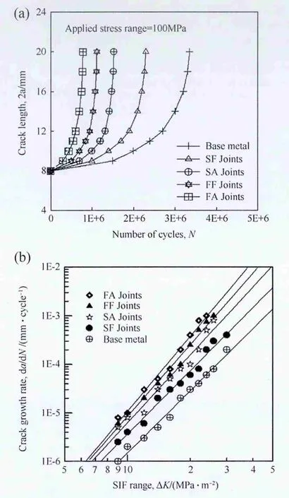
Fig.5.(a)Fatigue crack growth curves.(b)Relationship between crack growth rate and SIF range.
The fracture mechanics based Paris power equation[15]given below was used to analyse the experimental results.

where da/dN-crack growth rate,ΔK-Stress intensity factor(SIF)range,‘C’and ‘m’are constants.
The SIF value was calculated for different values of growing fatigue crack ‘2a’using the following expression[16]

However,the geometry factor ‘φ’for the CCT specimen was calculated using the expression given below[17];

where ‘a’is half crack length and ‘W’is the width of the specimen.
The crack growth rate,da/dN for the propagation stage was calculated for the steady state growth regime,at different intervals of crack length increment,against the associated number of cycles to propagation.The relationship between SIF range and the corresponding crack growth rate in terms of best fi t line is shown in Fig.5b.The data points plotted in the graph mostly correspond to the second stage of Paris sigmoidal relationship(10-6to 10-3mm/cycle).The exponent‘m’,which is the slope of the line on log-log plot and the intercept‘C’of the line,were determined and they are presented in Table 3a.
When the crack growth rate was just above 10-3mm/cycle,the unstable crack growth occured and the corresponding ΔK value was taken as critical SIF range(ΔKcr).Similarly,when the crack growth rate was just below 10-6mm/cycle,the crack growth rate is very slow and the corresponding ΔK value was taken as threshold SIF range(ΔKth).The values of ΔKcrand ΔKthfor all the joints were evaluated and presented in Table 3a.Normally,in case of steels,the threshold values are obtained to a crack growth rate of 10-8mm/cycle.Because of the specimen con fi guration and loading conditions,crack propagation rate in the region of 10-8mm/cycle could not be obtained.The fatigue crack growth (fracture mechanics)parameters of the base metal and welded joints are presented in Table 3a.
The crack growth exponent‘m’,which is derived from the relationship existing between crack growth rate(da/dN)and SIF range,is an important parameter to evaluate the fatigue crack growth behaviour of materials since it decides the fatigue crack propagation life of the materials.This exponent will be obtained from the slope of the curve drawn between da/dN and SIF range.If this exponent is lower,then slope of the curve is lower and that indicates the resistance offered by the material to the growing fatigue crack is higher and hence the fatigue life will be longer.If this exponent is larger,then slope of the curve is higher and that explains the resistance offered by the material to the growing fatigue crack is lower and hence the fatigue life will be shorter[18,19].The fatigue crack growth exponent of unwelded armour grade Q&T steel base metal is 4.04.But the fatigue crack growth exponent of SA,SF,FA and FF joints are 4.63,4.31,5.12 and 4.88.This indicates that the crack growth exponents of the welded joint are higher than the base metal.From the experimental results of fatigue crack growth results of armour grade Q&T steel joints,it is inferred that(i)the use of LHF steel consumables are found to be bene fi cial to enhance the fatigue crack growth resistance of armour grade Q&T steel joints compared to ASS consumables irrespective of the welding process used.(ii)Of the four joints,SF joints exhibited the lowest fatigue crack growth exponent value and offered superior fatigue crack growth resistance than all other joints considered in this investigation,(iii)The base metal offered better fatigue crack growth resistance than all the joints due its high strength.

Table 3aFatigue crack growth parameters of welded joints.
3.2.Residual stresses
Table 3b presents the measured residual stress values(measured by X-ray stress analyzer Make:Stresstech OY,Finland)at two different conditions:(i)In welded jointsresidual stresses are measured in the weld metal region after welding;(ii)In CCT specimens-residual stresses are measured at the notch tip of the CCT specimens before fatigue testing.From the results of residual stress measurement,it is inferred that,(i)Tensile residual stresses are predominant in weld metal region of all the joints,(ii)The ASS joints(SA and FA)have lower magnitude of residual stress in weld metal region than their LHF counterparts(SF and FF)because of difference in coefficient of thermal expansion and heat input used for welding.(iii)In the CCT specimen,the original tensile residual stress caused by welding process is relieved and subsequently,compressive stress field is generated due to the compressive load acted on the specimen during machining and grinding operations.
3.3.Transverse tensile properties
The transverse tensile properties such as yield strength,tensile strength,percentage of elongation,percentage of reduction in cross-sectional area and joint ef ficiency of welded joints were evaluated and presented in Table 4.The SF joints exhibited the superior tensile properties than SA,FA and FF joints.The FA joints showed the inferior tensile properties than other joints.However,the base metal tensile properties are superior than other joints.A joint ef ficiency of 66%in SF joint and 62%in FF joint are recorded.But the SA and FA joints showed a joint ef ficiency of 50%and 44%,respectively.The joints fabricated by using LHF consumables exhibited superior transverse tensile properties than the joints fabricated by ASS consumables irrespective of the welding process used.The transverse tensile properties of the joints fabricated using SMAW process were higher than their FCAW counterparts irrespective of the consumables used.Of all the four joints considered in this investigation SF joint fabricated using LHF consumable by SMAW process offered superior transverse tensile properties.
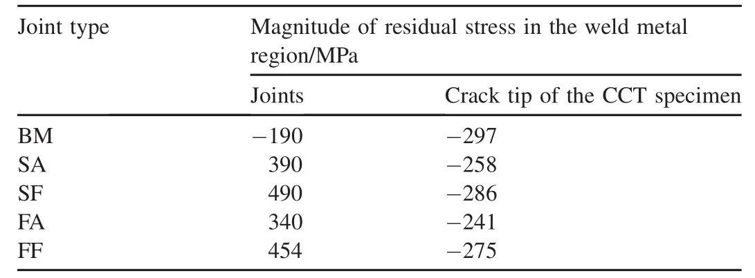
Table 3bResidual stress values before and after notching in CCT Specimen.

Table 4 Transverse tensile properties of base metal and welded joints.
3.4.Microstructure and hardness
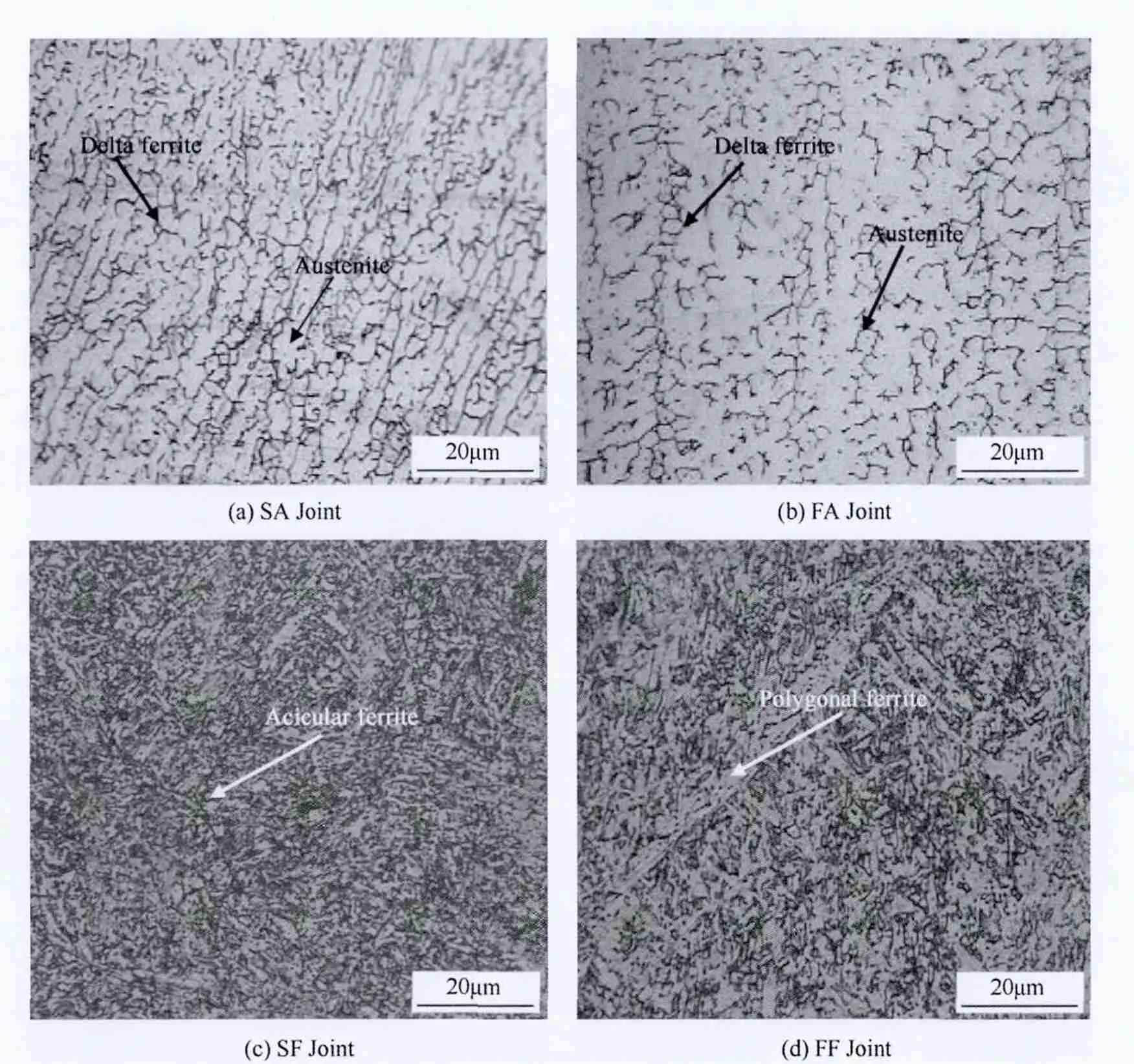
Fig.6.Optical micrographs of weld metal region.
The micrographs taken at the weld metal region and HAZ are alone displayed in Figs.6 and 7 respectively.The micrograph,taken at the weld metal region of the SA joint,exhibits a very fine skeletal delta ferrite in plain austenitic matrix(Fig.6a).The weld metal of the FA joint exhibits a much coarse skeletal network of delta ferrite in plain austenitic matrix(Fig.6b).The SF joint exhibits fully acicular ferrite morphology(Fig.6c)where as weld metal of FF joint shows polygonal ferrite matrix(Fig.6d).In all the joints,the HAZ region invariably consists of untempered martensite(Fig.7a-d).However,the degree of fineness is not similar in all cases.The HAZ region of SF weld(Fig.7c)contains very fine untempered martensite than SA weld(Fig.7a).Similarly HAZ region of FA weld(Fig.7b)shows coarser untempered martensite than that of FF weld(Fig.7d).The resultant of the microstructural heterogeneity is depicted in the hardness values of the weld region and HAZ region of all the joints presented in Table 5.The hardness of the unwelded base metal is 455 VHN.SA joint exhibits a hardness of 261 VHN in the weld metal region,while FA joint recorded 245 VHN.Similarly the weld metal hardness is found to be 311 VHN and 294 VHN for SF and FF joints,respectively.The hardness in the HAZ region for SF,SA,FF and FA welds are 443 VHN,437 VHN,427 VHN and 424 VHN respectively.Thus the joints fabricated using LHF consumables exhibited higher hardness in weld metal region and in HAZ region than the joints fabricated using ASS consumables irrespective of the process used.Also,the joints fabricated by SMAW process exhibited higher hardness in both weld metal region and in HAZ region irrespective of the consumable used.However,the SF joints fabricated using LHF consumable by SMAW process exhibited higher harness in weld region and HAZ region than all other joints considered in this investigation.
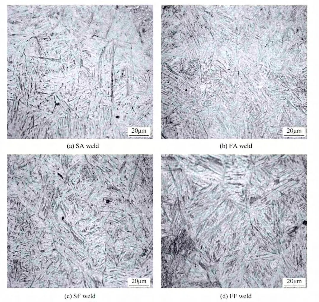
Fig.7.Optical micrographs of HAZ region.

Table 5 Microhardness(VHN)values(0.5 kg load).
3.5.Fractographs
The fatigue fracture surface appearance corresponding to crack initiation,crack propagation and the final failure regions of all the joints,as observed under the Scanning Electron Microscope(SEM)is displayed in Figs.8-10.Here,the fatigue crack initiation region(FCI)is corresponding to 1 mm from the tip of the machined notch;fatigue crack propagation(FCP)region is referred to 1-6 mm; final failure(FF)region is referred to 6 mm away from the crack initiation region.In all the joints,the crack initiations sites are clearly visible in FCI region and it can be observed from the fractographs that the fatigue cracks have initiated from multiple sites.FCP regions(where steady state crack growth occurs)of all the joints,invariably contain the micro-level striations but and the spacing between the striations varies appreciably.Even though unstable crack growth occurs in the final failure region,the final fracture is still in the ductile mode and it is evident from the presence of dimples.But the shape and size of the dimples are different in all the joints and it is in fluenced by the microstructure of the weld metal region.From the fractographs displayed in Figs.8-10,the following observations can be made.The number of crack initiation sites is relatively lower in LHF joints compared to ASS counterparts(Fig.8).The spacing between micro-level striations is much lower(closely spaced)in LHF joints compared to ASS joints(Fig.9).The final failure region of LHF joints exhibit finer dimples compared to ASS joints(Fig.10).
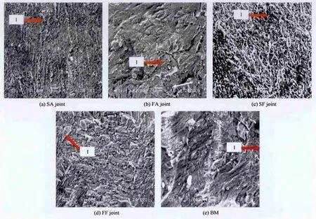
Fig.8.Fractographs of the crack initiation region.I:Crack initiation sites.
4.Discussion
The experimental results obtained from the fatigue crack growth tests indicate that the base metal offered superior resistance for the growing fatigue cracks than all other joints.However,the joints fabricated using LHF consumables exhibited superior fatigue crack growth resistance than other joints,irrespective of the welding processes used.Also,the joints fabricated using SMAW process offered better fatigue crack growth resistance than the joints fabricated using FCAW process irrespective of consumables used.Of the fi ve joints,the SF joints(joints fabricated using LHF steel consumable by SMAW process)offered superior fatigue crack growth resistance.The main factors that are responsible for better fatigue crack growth resistance are explained below.
4.1.Preferable microstructure
4.1.1.Effect of welding consumables on fatigue life
The use of ASS and LHF consumables for welding armour grade Q&T steel led to formation of distinct microstructures in their respective welds and in HAZ region.This microstructural heterogeneity have a drastic in fluence on the hardness of weld region,hardness of HAZ region tensile strength and thereby fatigue crack growth resistance of the joints.The Four joints joints,namely,SA,SF,FA and FF are characterized by different weld region microstructural features as shown in Fig.6.This inherent inhomogeneity in weld metal microstructure is due to the difference in the weld metal chemistry and weld thermal cycle.The microstructure of weld metal region in SF(Fig.6c)joint is more of acicular ferrite.A good combination of strength and toughness of low-carbon steel welds is achieved by so called acicular ferrite microstructure,consisting of small interweaving ferrite plates formed within austenite grains and it is the most desired structure in low carbon steels.Acicular ferrite is a phase most commonly observed as austenite transforms during the cooling of low alloy steel weld deposits.It is of considerable commercial importance because it provides a relatively tough and strong microstructure[20].It is generally believed that microstructure that contains predominantly acicular ferrite displays an optimum weld metal strength and toughness properties when compared with other forms of ferrite microstructures.This is attributed to its fine grain size(typically 1-3 μm)in which each lath is separated by high angle boundaries[21]and resulting in higher hardness values(311 VHN)compared to all other joints.
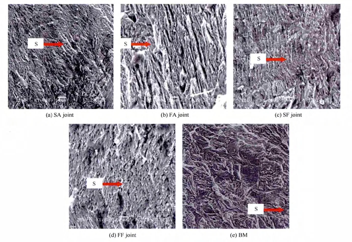
Fig.9.Fractographs of the crack propagation region.S:Striations.
The weld metal chemistry of SA and FA joints show 9.18(wt%)and 8.36(wt%)of nickel content respectively.Being an austenite stabilizer,it in fluences the formation of austenitic phase in the SA and FA weld metal regions.Microstructure of weld metal region of SA joint has a very fine skeletal delta ferrite(Fig.6a)in a plain austenitic matrix.It is well known that nickel in weld metal plays an important role in microstructural control.It has been reported that the weld metal toughness can be increased signi fi cantly by an increase of Ni content[22].But Ni reduces the transverse tensile strength and weld metal hardness of SA joints(261 VHN)which are much lower than that of the SF(311 VHN)joints due to the presence of rich austenitic phase.Thus,the SA joint has inferior transverse tensile properties and hardness values than SF joint because austenitic phase in the weld metal microstructure.Similarly the FA joint fabricated using austenitic stainless steel fl ux cored wire has lower transverse tensile strength and weld metal hardness(245 VHN)due to the presence of rich austenitic phase and a coarse delta ferrite morphology(Fig.6b)in microstructure of weld metal region than of FF joint fabricated using low hydrogen ferritic fl ux cored wire is because of the presence of polygonal ferrite microstructure(Fig.6d)and higher hardness values(294 VHN).Moreover it is evident from the HAZ microstructure(Fig.7),all the joints,the HAZ region invariably consists of untempered martensite.However,thejointfabricated using LHF consumables exhibited higher hardness values than the joints fabricated using ASS consumables and their HAZ microstructures are finer(Fig.7c and d)in the HAZ region.Hence,the joints fabricated using low hydrogen ferritic steel consumables exhibited superior transverse tensile properties and fatigue crack growth resistance than their austenitic stainless steel counterparts irrespective of the process used.Welds with acicular ferrite type of morphology have higher hardness and yield strength.The SF joint exhibits superior fatigue crack growth resistance due to the presence of acicular ferrite morphology in the weld metal region.An acicular ferrite microstructure has the potential of combining high strength and high toughness[23].The acicular ferrite in the weld metal regions caused repeated de fl ection and branching of the propagating fatigue crack,thereby reducing the effective stress intensity conditions at the crack tip and retarding crack growth rates in these regions[24,25].Hence,the fatigue crack growth resistance of the SF joints are greater compared to other joints.
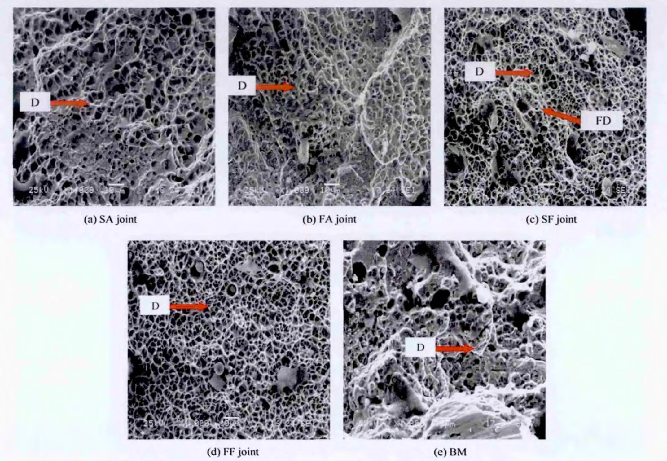
Fig.10.Fractographs of the final failure region.D:Dimples;FD:Fine dimples.
4.1.2.Effect of welding processes on fatigue life
It is a common practice to correlate the various weld metal properties with heat input.The difference in the ferrite morphology in high strength steel welds is due to the difference in heat input.The formation of acicular ferrite is controlled by weld heat input.Thus if the heat input is higher the content of the acicular ferrite will be very less and vice versa.On the other hand higher heat input will enhance the formation of coarse pro-eutectoid ferrite or polygonal ferrite in the weld metal region[26,27].Weld cooling rate plays the decisive role in determining weld microstructure in high strength steels.The general effect of increasing the cooling rate is to lower transformation temperatures.When cooled at suf ficiently low rates,the microstructure predominantly tends to become polygonal ferrite[28,29].In the present investigation,heat input of 1.22 kJ/mm was recorded during the fabrication of SF joint and 2.03 kJ/mm was recorded during fabrication of FF joint.The microstructure of the weld metal region of SF joint reveals acicular ferrite(Fig.6c)while the weld metal region of FF joint reveal polygonal ferrite structure(Fig.6d).An acicular ferrite microstructure has the potential of combining high strength and high toughness.Also,the HAZ microstructure of the SF joints exhibited much finer untempered martensite(Fig.7c)compared to FF joint(Fig.7d).This imparted higher hardness(in both weld metal region and HAZ region)and superior transverse tensile properties to SF joints compared to FF joints.Hence,the SF joints exhibited superior fatigue crack growth resistance than the FF joints under the action of fatigue loading.
The subject of delta in ASS welds is much of importance to a greater extent.Delta ferrite in weld metal cannot be accurately predicted from chemical composition.Delta ferrite is not homogenous in chemical composition and is not uniformly distributed and has preferred orientations when very finely distributed.Delta ferrite in welds depends on chemistry,and thermal history of the deposit.The microstructure of the weld deposits depends on the quantity of the ferrite which exist soon after the solidi fi cation which in turn on the relative proportions of the austenite and ferrite forming elements.The delta ferrite in weld metal is in fluenced by the cooling rate of the molten metal;cooling rate depends upon the heat input and thickness of the base metal.Heat input and cooling rates associated with SMAW process and FCAW process have been identi fi ed to be the factors responsible for resulting features of delta ferrite morphology in the austenitic stainless steel weld metal.Coarseness of the delta ferrite distribution is attributed to substructure size,which in turn is governed by relative weld energy heat-input utilized[30].Variation in amount and distribution of the ferrite phase is due to the inherent heterogeneity of the weld-metal solidi fi cation process. The microstructures and mechanical properties of stainless steel were studied using a directional solidi fi cation technique and it is found that the cooling rates associated with weld deposits have a strong in fluence on the characteristics yielding different microstructures and showing a marked difference in mechanical behaviour.Heat input and cooling rate affected the morphology:size,shape and distribution of ferrite.Ferrite becomes finer as the welding energy is decreased and as the cooling rate is decreased.The solidi fi cation behaviour and subsequent solid state transformations are in fluenced by cooling rates associated with welding[31].The cooling rates associated with SA and FA joints in the present study are not quanti fi ed.However,FCAW process which is characteristic of higher deposition rate with relatively higher heat input(2.37 kJ/mm)as compared with the SMAW process that has lower heat input(1.60 kJ/mm)seems to have altered the cooling rates in the FA joint weld metal resulting differences in the primary austenitic phase and secondary delta ferrite phase respectively.This resulted in the higher hardness(in both weld metal region and HAZ region)and superior transverse tensile properties of SA joint compared to FA joints.Thus,SA joints exhibited superior fatigue crack growth resistance than FA joints.From the above discussion,it is very clear that welding processes and consumables have a signi ficant role on the weld metal microstructures and their morphologies.This has a direct in fluence on the tensile properties and toughness which has a direct effect on fatigue crack growth resistance of the armour grade Q&T steel joints.Thus the joints fabricated using SMAW process exhibited better fatigue resistance than their FCAW counterparts irrespective of the consumables used.
4.2.Superior mechanical properties
High cycle fatigue is stress-controlled process and as the applied stress range is always below the yield strength of the material.If the yield strength of the material is higher,then the fatigue limit of the material will be higher.Hence,the higher yield strength materials will endure higher number of cycles under the action of fatigue loading.Further,higher yield strength material will have higher internal energy(area under the curve is large in elastic region)and that will be bene fi cial to resist a growing crack.In the CCT specimen,the notch is machined in the weld metal region of welded joints by wire cut EDM(electric discharge machining)process to evaluate the crack growth behaviour of the weld metal under fatigue loading.The fatigue crack initiates from the tip of the machined notch and it grows in the weld metal until final failure takes place and hence the weld metal microstructure will have an in fluence on fatigue performance of the joints.The presence of larger proportion of austenitic phase in the weld metal region and a coarse HAZ microstructure of the joints fabricated using ASS consumables resulted in lower hardness and hence lower tensile strength than their LHF counterparts irrespective of the welding process used.Thus tensile properties(yield strength,tensile strength and elongation)of joints fabricated using LHF consumables are superior as compared to their ASS counterparts(see Table 4).Higher yield strength and tensile strength of the LHF joints are greatly used to enhance the endurance limit of the joints and hence the fatigue crack initiation is delayed.Larger elongation(higher ductility)of the LHF joints also imparts greater resistance to fatigue crack propagation and hence fatigue failure is delayed.The combined effect of higher yield strength and higher ductility of the LHF joints offers enhanced resistance to crack initiation and crack propagation and hence the fatigue performance of the joints is superior as compared to their ASS counterparts irrespective of the welding process used.
In the lower strength weld metal,as in the case of joints(SA and FA)fabricated using ASS consumables,since the deformation and the yielding are mainly concentrated in the weld metal zone,the extension of the plastic zone is limited within the weld metal.As soon as the plastic zone reaches the fusion line,plasticity keeps on developing along the interface between the parent material and the weld metal[32].The triaxial state of stress is high in the weld metal and the relaxation of this stress is poor.The crack driving force needed for crack extension is small.So,the fracture toughness of the lower strength weld metal is not high.On the other hand,if strength of the weld metal is higher,the plastic zone can easily extend into the parent material because the deformation and yielding occur in both weld metal and the base metal.The stress relaxation can easily take place in the crack tip region.So more crack driving force is needed for crack extension and the fracture resistance of the higher strength weld metal is greater than the lower strength weld metal[33-36].This is also one of the reasons for better fatigue resistance of the LHF joints compared to ASS joints irrespective of the welding process used.
Of all the four joints,the SF joint fabricated using LHF consumable by SMAW process exhibited superior fatigue crack growth resistance.As already stated the weld metal region of the SF joints is revealed by the presence of most preferable microstructure namely acicular ferrite(Fig.7c).As described by Liv and Olson[28]acicular ferrite is formed intragranularly,resulting in a randomly oriented short ferrite needles with basket-weave feature and hence the hardness is higher.This interlocking nature together with its fine grain size,provides maximum resistance to crack propagation by cleavage.Moreover,acicular ferrite is characterized by high angle boundaries between ferrite grains.The acicular ferrite in the weld metal regions caused repeated de fl ection and branching of the propagating fatigue crack,thereby reducing the effective stress intensity conditions at the crack tip and retard crack growth rates in these regions[37].This is also one good reason for the superior fatigue crack growth resistance offered by SF joint than all other joints.Also,the mechanical properties(yield strength,tensile strength and elongation)of SF joints are superior as compared to other joints(Table 5)Higher yield strength and tensile strength of the SF joint is greatly used to enhance the endurance limit of the SF joints and hence the fatigue crack initiation is delayed.Larger elongation(higher ductility)of the SF joints also imparts greater resistance to fatigue crack propagation and hence fatigue crack growth rate is comparatively slower.Hence,SF joints exhibits superior fatigue crack growth resistance than all other joints considered in this investigation.
4.3.Favourable residual stresses
During heating cycle,the expansion of weld metal is resisted by the surrounding base metal but during cooling cycle,the contraction of weld metal is also resisted by the surrounding base metal.Due to the restraint offered by the base metal during expansion and contraction of weld metal,a tensile residual stress field is generated in the weld metal region If the yield strength of the base metal is higher than the weld metal,then the restraint offered by the base metal will be higher and consequently the magnitude of tensile residual stress will be greater.Hence,in this study the residual stresses are higher in weld metal region of all the joints compared to the base metal.Table 3b shows the measured residual stress values(measured by X-ray stress analyzer Make:Stresstech OY,Finland).In the CCT specimens,the measured residual stress values are compressive and this is mainly due to the reason that after welding the joints were sliced,machined and ground to obtain the required dimensions of CCT specimen.Because of the above mentioned machining operations,the original tensile residual stresses caused by welding operation are relieved and subsequently,compressive stress fields are generated due to the compressive load acted on the specimen during grinding operation.
Residual stresses,which arise in welded joints as a consequence of incompatible thermal strains caused by heating and cooling cycles,also have signi fi cant effect on the fatigue life of welded structures[37].When a fatigue crack is propagating through a residual stress field in welded plate,the stress intensity at the crack front is in fluenced by the combined effect of local residual stress and the stress resulted from externally applied stress.It means that the effective stress intensity factor of the crack front is sum of stress intensity factor due to residual stresses and the stress intensity factor due to external loading.In the presence of residual stresses,the CTOD(crack tip opening displacement)for a crack in weld metal was always larger than the value for a crack in homogeneous plate at the same load[38].
Even though the compressive load acts on the specimen during grinding is uniform,the resultant residual stress values are different and this may be due to the differences existed in the original(welded condition)residual stress values.From the measured residual stress values(Table 3b)can be inferred that the magnitude of resultant compressive stress field in SF joint is relatively higher than the other joints.This may be also one of the reasons for slower fatigue crack growth rate observed in SF joints compared to other joints,since compressive residual stresses usually retard the rate of fatigue crack growth[9].
The formation of a favourable compressive residual stresspattern at the surface is probably the most effective method of increasing fatigue performance.For many purposes residual stresses can be considered identical to the stresses produced by an external force.Thus,an addition of a compressive residual stress,which exists at a point on the surface,to an externally applied tensile stress on that surface decreases the likelihood of fatigue failure at that point[39,40]and hence,a higher compressive stress at the crack tip of the CCT specimen of the SF joints contributes for a higher fatigue crack growth resistance than other joints.
5.Conclusions
In this paper,the effect welding consumables and welding processes on fatigue crack growth behaviour of armour grade Q&T steel joints was analysed in detail.From the above illustrations,the following conclusions are derived:
1)The use of low hydrogen ferritic steel consumables is found to be bene fi cial to enhance the fatigue crack growth resistance of armour grade Q&T steel joints than the joints fabricated by conventional ASS consumables.
2)The joints fabricated by SMAW process offered superior fatigue crack growth resistance compared to FCAW counterparts irrespective of the consumables used.
3)The superior mechanical properties(higher yield strength and toughness),preferable microstructures (acicular ferrite)in the weld metal region and bene fi cial residual stress field(compressive residual stress)of the weld region are the reasons for better fatigue crack growth resistance of the SF joints.
4)From this investigation,it is found that the joints fabricated using low hydrogen ferritic fi llers showed preferable ferrite microstructure in the weld metal region along with higher tensile strength,greater weld metal hardness,and superior fatigue crack growth resistance than other joints.Hence,it is recommended that low hydrogen ferritic consumables can also be used for welding armour grade Q&T steels.
Acknowledgements
The authors are thankful to M/s Combat Vehicle Research Development Establishment(CVRDE),Avadi,Chennai for providing base material and extending fabrication facility for joint fabrication,M/s Defence Metallurgical Research Laboratory(DMRL),Hyderabad for providing characterization facility and DepartmentofManufacturing Engineering,Annamalai University for providing testing facility for this investigation.The authors are also thankful to Armament Research Board(ARMREB),New Delhi for funding this project work(Project No MAA/03/41).
[1]Ade F.Ballistic quali fi cation of armour steel weldments.Weld J 1991;70:53-4.
[2]Coe FR.Welding steels without hydrogen cracking.Cambridge:Abington Publishing;1973.
[3]Madhusudhan Reddy G,Mohandas T,Tagore GRN.Weldability studies on high-strength low-alloy steel using austenitic stainless steel fi ller.J Mat Proc Tech 1995;49:213-28.
[4]Deb P,Challenger KD,Clark DR.Transmission electron microscopy characterizations of preheated and non-preheated shielded metal arc weldments of HY-80 steel.Mater Sci Eng 1988;77:155-67.
[5]Cary HB.Modern welding technology.3rd ed.London:Prentice-Hall,Inc.;1994.
[6]Magudeeswaran G,Balsubramanian V,Madhusudhnan Reddy G.Hydrogen induced cold cracking studies on armour grade quenched and tempered steel weldments.Int J Hydrogen Energy 2008;33:1897-908.
[7]Alkemade SJ.The weld cracking susceptibility of high hardness armour steel.Australia:Defense Science and Technology Organization;1996.pp.1-17.AR No 009-659.
[8]Wilson J.The development of welding techniques for British fi ghting vehicles.U.K:Crown Copyright;1978.
[9]Radaj D,Sonsino CM,Flade D.Prediction of service fatigue strength of a welded tubular joint on the basis of the notch strain approach.Int J Fat 1998;20:471-80.
[10]Teng TL,Fung CP,Chang PH.Effect of residual stresses on the fatigue of butt joints using thermal elasto-plastic and multiaxial fatigue theory.Eng Fail Anal 2003;10:131-51.
[11]Taylor D,Barrett N,Lucano G.Some new methods for predicting fatigue in welded joints.Int J Fat 2002;24:509-18.
[12]Yakubovski VV,Valteris II.Geometrical parameters of butt and fi llet welds and their in fluence on the welded joint fatigue life.Int Int Weld;1989:1326-69.Doc XIII.
[13]Gupta B.Indian armour steel-a review.Technical report.Chennai,India:Combat Vehicle Research Development;1974.pp.2-30.
[14]Paris PC,Erdogan F.Basic engineering.Trans ASTM J;1963:528-34.[15]Knott JF.Fundamentals of fracture mechanics.London:Butterworths Press;1973.
[16]Hellan K.Introduction to fracture mechanics.2nded.New York:McGraw Hill Book Company;1984.
[17]Meyers,Chawla.Mechanical behaviour of materials.New Jersey:Prentice-Hall,Inc;1984.
[18]Guha B.A new fracture mechanics method to predict the fatigue life of welded cruciform joints.Eng Fract Mech 1995;52:215-29.
[19]Barbaro FJ,Krauklis P,Easterling KE.Formation of acicular ferrite at oxide particles in steels.Mat Sci Tech 1989;5:1057-68.
[20]Parmar RS.Welding engineering and technology.2nd ed.New Delhi:Khanna Publishers;2003.
[21]Rao EJ.Studies on fatigue crack growth behaviour of welded cruciform and butt joints of a low alloy(Q&T)high strength steel with austenitic and ferritic fi llers.Ph.D Thesis.India:IIT-Madras;1997.
[22]Bhadeshia HKDH.Some phase transformations in steels.Mat Sci Tech 1999;5:22-30.
[23]Brat PE,Braglia BL,Hertzberg RW.Fatigue behaviour of HSLA steel and associated weldments.In:Proc of the 5th Bolton Landing conference,USA;1978.pp.271-84.
[24]Bhadeshia HKD,Svensson LE,Gretoft B.A model for the development of microstructure in low-alloy steel(Fe-Mn-Si-C)weld deposits.Acta Met 1985;33:1271-83.
[25]Wang J,Li YJ.Microstructure characterization in the weld metals of HQ130+QJ63 high strength steels.Bull Mat Sci 2003;36:35-9.
[26]Dixon B,Hakansson K.Effect of welding parameters on weld zone toughness and hardness in 690 MPa steel.Weld J 1995;64:122s-4s.
[27]Liv S,Olson DL.The role of inclusions in controlling HSLA steel weld microstructures.Weld J 1986;65:139s-49s.
[28]Harrison P,Farrar R.Microstructure and toughness of C-Mn and CMn-Ni weld metal-part I.Met Const 1987;7:392R-9R.
[29]Bhadeshia HKDH,Svensson LE.Strong and tough welds.In:Proc mathematical modeling of weld phenomena-VI.London:Institute of Materials;1993.pp.109-82.
[30]Elmer JM,Allen SM,Eager TW.The in fluence of cooling rate on the ferrite content of stainless steel alloys.In:Proc of international conference(ASME)on recent trends in welding science and technology,USA;1999.pp.147-53.
[31]David SA,Broski DN,Goodwin GM.Solidi fi cation behaviour of austenitic stainless steel fi ller metal.Weld J 1979;58:330s-6s.
[32]Eripret C,Hornet P.Prediction of overmatching effects on the fracture of stainless steel cracked welds.In:Mis-matching of welds,ESIS 17.London:Mechanical Engineering Publications;1994.pp.685-708.
[33]Tang W,Shi YW.In fluence of strength matching and crack depth on the fracture parameters of welded joints.In:ESIS 17,mis-matching welds.London:Mechanical Engineering Publications;1994.pp.433-43.
[34]Maddox SJ.Fatigue strength of welded structures.3rd ed.London:Cambridge University Press;1991.
[35]Mayer H,Papakyriacou M,Pippen R,Stanzl-Tschegg S.In fluence of loading frequency on the high cycle fatigue properties of Al-Zn-Mg-Cu 1.5 aluminium alloy.Mat Sci Eng-A 2001;314:48-54.[36]Balasubramanian V,Ravisankar V,Madhusudhan Reddy G.In fluences of pulsedcurrentweldingandpostweldagingtreatmentonfatiguecrackgrowth behaviour of AA7075 aluminium alloy joints.Int J Fat 2008;30:405-16.
[37]Howell RA,Barritte GS.The nature of acicular ferrite in HSLA steel weld metals.J Mat Sci 1985;17:732-40.
[38]Smith SD,Pisaraski HG,Leggast RH.In fluences of residual stresses on crack driving force for weld metal with under and over matching yield strength.Mis-matching of welds.London:Mechanical Engineering Publications;1994.pp.573-87.
[39]Nguyen T,Ninh,Wahab MA.The effect of residual stresses and weld geometry on the improvement of fatigue life.J Mat Proc Tech 1995;48:581-8.
[40]Dieter GE.Mechanical metallurgy.New York:Tata McGraw Hill;1988.
- Defence Technology的其它文章
- Estimation of the kinetic parameters for thermal decomposition of HNIW and its adiabatic time-to-explosion by Kooij formula
- Research on design and firing performance of Si-based detonator
- Analysis of hydrodynamic characteristics of unmanned underwater vehicle moving close to the sea bottom
- Dynamic globularization prediction during cogging process of large size TC11 titanium alloy billet with lamellar structure
- A numerical study on the disturbance of explosive reactive armors to jet penetration
- Biased retro-proportional navigation law for interception of high-speed targets with angular constraint

