
Disassemblability Modeling Technology of Configurable Product Based on Disassembly Constraint Relation Weighted Design Structure Matrix(DSM)
2014-03-01 01:48QIULemiaoLIUXiaojianZHANGShuyouandSUNLiangfeng
QIU Lemiao , LIU Xiaojian, ZHANG Shuyou, and SUN Liangfeng
The State Key Lab of Fluid Power Transmission and Control, Zhejiang University, Hangzhou 310027, China
1 Introduction
According to predefined component sets and the constraint relations between them, product configuration design can quickly generate customized products satisfying individual demands of customers. Configuration modeling is the core technology to achieve product configuration design, and experts and scholars have done a lot of research on it. WANG, et al[1], proposed an case-based product configuration model(CPCM), which is to search similar design cases in case base, to use the constraint relations in the found cases as the initial values of restraint variables in new problems, and to use constraint satisfaction problem(CSP) to modify cases. For configuration problems of mass customization with modular characteristics, ZHU, et al[2],put forward a generalized product configuration model,which is based on virtual modules and driven by customer requirements. On the basis of characteristics of configurable product, WANG, et al[3], proposed a product configuration model using generic Bill-of-Materials(GBOM) as a product family. SOININEN, et al[4–6],established a constraint-based configuration model, in which the constraints of product function and structure are extracted, so the configuration problem is solved as a constraint satisfaction problem, and the problem description and problem solving are divided into two separate components. Parameters, components and interfaces of configuration design are defined as variables,and parameters relation, components selection and other technical requirements are expressed by constraints.HUANG, et al[7], proposed a new approach by means of characteristic state space is presented to improve the efficiency of the configuration selection for reconfigurable manufacturing systems. WEI, et al[8], studied the multistage rhombus evolution mode of configuration knowledge. The product model based on configuration knowledge is put forward in different levels to achieve the models dynamic evolvement and automatic upgrading. The evolving configuration knowledge drives the product model to evolve directly according to the rule of up-layer evolvement.
Product lifecycle oriented product design requires taking product repair and recycling issues into consideration in the design stage, and product disassemblability evaluation and disassembly sequence planning are the foundation of design for disassembly. MOK, et al[9], proposed criteria and evaluation indicators for design for disassembly, and a scoring method is used for quantitative evaluation of product disassemblability. SODHI, et al[10–12], used disassembly force, tool positioning accuracy, disassembly accessibility and materials of components to be disassembled, as well as disassembling methods as evaluation indicators, and used time to quantify these indicators to evaluate product disassemblability. GARCÌA,et al[13], proposed a disassembly sequence optimization method based on deep-first graphic searching to solve problems of batch disassembly of components and accessibility of tools for dismantling fasteners. CHUNG, et al[14], proposed an integrated and selectivity disassembly method, to get the target components by finding subassembly containing target components. SRINIVASAN,et al[15], proposed a selectivity disassembly sequence planning method based on disassembly wave propagation(DWP), in which component arrangements associated with the target components are defined as disassembly waves,and the converge of waves is used to get a set of selectivity disassembly sequences. ZHANG, et al[16], constructed a disassembly hybrid graph model(DHGM) for describing the mating contact and non-contact priority relationships among constituting product components. a novel method is presented to generate cooperative disassembly hierarchical tree(CDHT) from the DHGM based on branch-and-bound algorithm in which two user-defined variables are introduced to control the size of the CDHT. SMITH, et al[17], introduced a new disassembly sequence structure graph(DSSG) model for multiple-target selective disassembly sequence planning, an approach for creating DSSGs, and methods for searching DSSGs. The DSSG model contains a minimum set of parts that must be removed to remove selected targets, with an order and direction for removing each part. The approach uses expert rules to choose parts, part order, and part disassembly directions, based upon physical constraints. The searching methods use rules to remove all parts, in order, from the DSSG. BEHDAD, et al[18], presented a method for addressing these tradeoffs, as well as the uncertainty associated with them. A procedure for identifying the best sequence of disassembly operations for maintenance component upgrade is presented. It considers both disassembly and reassembly costs and uncertainties.Graph-based integer linear programming combined with multi-attribute utility analysis is employed to identify the best set of tradeoffs.
The above researches have made significant progress in product configuration design and product disassembly and have been applied in practice. However, there are few studies on disassemblability of configurable product. In this paper, product disassembly is taken into consideration in configuration modeling stage, and disassembly entropy is used to quantify the disassemblability of configurable product, and matrix decomposition and tearing operations are used to construct product disassemblability configuration models, to give configurable product with good maintenance, recovery and reuse properties.
2 Disassemblability of Configurable Product
2.1 Analysis on disassemblability of configurable product
To construct disassemblability configuration models, it is required to analyze the disassembly relations between configurable product components. The disassembly process of configurable product can be considered as a process to remove assembly constraints between components, and the disassemblability is reflected by the complexity of constraint release. Major factors affecting the disassemblability of configurable product include the following.
(1) Joint type. A variety of assembly joints are used between assemblies, and diverse joint types correspond to different disassembly methods and require different tools for dismantling, which influence the disassemblability and disassembly efficiency of configurable product greatly.
(2) Joint quantity. The disassembly of products mainly includes disassembling fastener joints and removal of subassemblies. The joint quantity has great influence on the disassemblability of configurable product. In disassembly,the joint quantity should be as little as possible, so that disassembly is easy and saves time and effort.
(3) Disassembly path. The path to remove subassemblies from products. The disassemblability of configurable product is directly related to the disassembly path,especially for assembly relations constituted by geometric constraints.
(4) Disassembly direction. Under assembly constraints,the available direction of movement of subassemblies, also called as disassemblability direction. The disassembly of configurable product is mainly to remove joint constraints,so the disassembly direction is directly related to disassembly efficiency.
(5) Disassembly level. The disassembly level reflects the relative position between subassemblies. Deeper subassembly requires a more complex disassembly process,so product disassembly levels should be minimized in product design.
(6) Disassembly accessibility. When disassembling a product, the operator can observe the components to be disassembled and tools for dismantling can reach the disassembly site. Disassembly accessibility is directly related to complexity of tools for dismantling and disassembly costs.
(7) Material compatibility. The materials of the components dissembled have the same way of recycling. If the materials of all components of a subassembly have compatibility, the entirely subassembly can be recycled without dismantling.
The disassembly of configurable product also involves disassembly tools, disassembly force, disassembly costs,disassembly time, and many other factors, which together determine the disassemblability of products.
2.2 Disassembly entropy of configurable product
Five major factors affecting product disassemblability are selected: joint type, joint quantity, disassembly path,disassembly accessibility and material compatibility. In this paper, disassembly entropy introduced by SUGA, et al[19–20]is expanded. The disassembly complexity of configurable product is quantitatively assessed using disassembly entropy. The smaller the disassembly entropy is, the better disassemblability between assemblies is.
(1) Disassembly entropy of joint type:

where Nmiindicates the total number of subassembly joints in the configurable product and Nmjis assembly joint number of type j.
(2) Disassembly entropy of joint quantity:

where Nqiindicates the total number of subassembly joints in the configurable product; Nqjis the number of components included in the subassembly.
(3) Disassembly entropy of disassembly path:

where Npiindicates the total number of disassembly paths of components of the subassembly of the configurable product; Npjis the number of disassembly paths in direction j.
(4) Disassembly entropy of accessibility:

where Naiindicates the total number of components in the subassembly of the configurable product; Najis the number of components of good accessibility.
(5) Disassembly entropy of material compatibility:

where Nriindicates the total number of assembly joints in the subassembly of the configurable product; Nrjis the number of joints with good compatibility.
3 DSM for Disassemblability Configuration Modeling
3.1 Design structure matrix
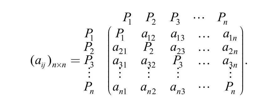
The design structure matrix(DSM) is an n×n square matrix, representing the disassembly constraint relations between components of the configurable product. The rows and columns of the matrix correspond to a group of components with the same sequence, that is Pi(i=1, 2, 3,…,n). The matrix elements represent the disassembly constraint relations between components. The element aijof the matrix may be “0” or “1”, where “0” indicates that there is no disassembly constraint relation between components Piand Pj, and “1” indicates that there is a disassembly constraint relation between components Piand Pj; the diagonal elements of the DSM are the components themselves. The form of DSM is shown below:
3.2 Disassembling degree between components of a configurable product
Major factors affecting configurable product disassemblability include joint type, joint quantity, disassembly path,disassembly accessibility and material compatibility. An integrated indicator-disassembling degree reflecting the disassemblability of a configurable product can be calculated by weighting the disassembly entropies of these aspects, with the following computation formula:
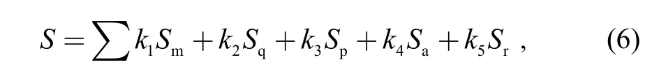
where ki(i=1, 2,…, 5; k1+k2+k3+k4+k5=1) is the weight of the disassembly entropy, and its value is determined by the degree of influence on the disassemblability of the configurable product. The disassembling degree fairly comprehensively reflects the disassemblability between components of a configurable product, and is the foundation of construct disassemblability configuration models.
3.3 Disassembly constraint relation weighted DSM
The design structure matrix can describe whether there is a disassembly constraint relation between components of configurable product but cannot reflect the strength of the disassembly constraint relation between components.Therefore, the components of strong disassembly constraint relations cannot be aggregated into a module through the transformation of the design structure matrix. Therefore,the design structure matrix is improved, a disassembly constraint relation weighted DSM based on disassembling degree is constructed. The main steps are as follows.
Step 1: Sorting of design structure matrix elements
Analyze the component composition of the configurable product, and create a component sequence Pi(i=1, 2, 3,…,n), which is used as the arrangement order of the design structure matrix elements.
Step 2: Determination of the design structure matrix elements
According to whether there is a disassembly relation between component Piand component Pj, let the matrix elementbe “0” or “1” to get the design structure matrix( aij)n×n.
Step 3: Calculation of disassembly entropies of components of the configurable product
Calculate the disassembly entropies of joint type, joint quantity, disassembly path, disassembly accessibility and material compatibility of any two components of the configurable product, denoted as: Sm, Sq, Sp, Sa, and Sr.
Step 4: Calculation of the disassemblability between components of the configurable product
With the disassembly entropies between components of the configurable product obtained in step 3, the disassembling degreei=1, 2, 3,…, n; j=1, 2, 3,…,n) between components of the configurable product is calculated according to Eq. (6); and the disassembling degree matrix of the configurable product( Sij)n×nis organized.
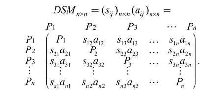
Step 5: Construction of the disassembly constraint relation weighted DSM
Taking the disassembling degree matrix of the configurable product( Sij)n×nas the weight matrix, the disassembly constraint relation weighted DSM is. Its form is as follows:
4 Configurable Product Disassemblability Modeling Based DSM
4.1 Modeling principles of disassemblability configuration
The traditional configuration modeling technology mainly constructs product configuration models through modules and constraint relations between modules, and the planning of the disassemblability between modules and components of modules is deficient. The disassembling degree can be obtained by calculating the disassembly entropies between components of the configurable product,and the configuration model can be reconstructed according to the principle of strong coupling of disassembly constraint inside modules and weak coupling of disassembly constraint between modules, so the disassembly of the configurable product only requires the release of weak disassembly constraints between modules,to achieve disassemblability modeling of configurable product. Shown in Fig.1, in the constructed disassemblability configuration model, the disassembly constraint ωibetween internal components of the configuration module(such as component aiin module A) is strong coupling and the disassembly constraint δibetween modules(such as configuration module A and configuration module B,reflected by the disassembly constraint between components a4and b1) is weak coupling.

Fig. 1. Disassemblability model of configurable product
4.2 Disassemblability modeling approach based on DSM transformation
Disassemblability modeling of configurable product requires to reduce the coupling strength of disassembly constraints between modules and to improve inter-module disassemblability. The basic method is to reconstruct the configuration module by matrix decomposition and tearing algorithm, turning the disassembly constraint inside the module into strong coupling and the disassembly constraint between modules into weak coupling.
(1) Decomposition of disassembly constraint relation weighted DSM
We observed rows and columns in the DSM, if all the elements of a row are zero, which means there is no other component inputting disassembly constraint, so the component can be arranged in the front of the matrix; if all the elements of a column are zero, which means that the component does not output disassembly constraint to other components, so the component can be arranged in the back of the matrix. Remove the arranged components and repeat the operation, until there is no empty row and column. To identify coupling strength of disassembly constraints,module intensity indicator(MII)[21]is defined, MII=MIIi–MIIo, where MIIirepresents the mean of disassembly constraint coupling between components inside the configuration module, and MIIorepresents the mean of disassembly constraint coupling between components inside the module and all external components.

where wijis the disassembling degree between components,r is the row(column) number of the first component of the configuration module, s is the row(column) number of the last component in DSM, and n is the total number of components in the configurable product. By solving MII,all possible disassembly constraint coupling component sets can be obtained. By setting threshold values, a configuration module can be constructed based on disassembly constraint coupling component sets.
(2) Tearing of disassembly constraint coupling component sets.
A disassembly constraint coupling component set is a matrix block of the DSM, representing to a configuration module. When disassembling a configurable product, it is required to consider disassembly sequence inside the module, and tearing operation can be conducted to the matrix block corresponding to a disassembly constraint coupling component set. Using the sensitivity algorithm[22],the disassembly constraint coupling strength of components inside the module can be calculated, based on which the internal disassembly sequence of the module can be generated. Let C be a disassembly constraint coupling component set, SIiand SOiare the input and output disassembly constraint coupling strengths of component i(i∈C), and then, Wi= SIi/ SOi.
By decomposition of weighted DSM and tearing of coupling matrix block, the internal disassembly constraints in configuration modules turn into strong coupling, and the external constraints turns into weak coupling, and the disassembly execution sequence inside the module has also been optimized.
5 Case Study of Disassemblability Configuration Modeling
For hydraulic forging presses produced by a certain company, the disassemblability configuration modeling process of the products is analyzed. The main structures of a hydraulic forging press include a left column, a right column, an upper beam, a lower beam, embedded blots, a top tank, a lower tank, tubing, etc. as shown in Table 1.

Table 1. Main components of hydraulic forging press
5.1 Construction of disassembly constraint relation weighted DSM of hydraulic forging press
(1) According to the structural composition of the hydraulic forging press, construct a disassembly constraint relation DSM
The main diagonal elements of the matrix are components sequence of the hydraulic forging press {P1,P2,…, P26}, the elements of a value of “1” in the row where component Pi(1≤i≤26) is located indicate that another element Pj(1≤j≤26, j≠i) has a disassembly constraint input relation to the component, and the elements of a value of “1” in the column where component Piis located indicate that the component has a disassembly constraint output relation to another element Pj(1≤j≤26,j ≠i). The DSM reflecting the disassembly constraint relations of main structures of the hydraulic forging press is shown in Fig. 2.
(2) Calculate inter-component disassembling degrees to obtain the disassembly constraint relation weighted DSM of the hydraulic forging press.
According to the joint type, joint quantity, disassembly path, disassembly accessibility and material compatibility of the hydraulic forging press, the disassembly entropies Sm,Sq, Sp, Sa, and Srare calculated; according to Eq. (6), the disassembling degree between any two components Sij(i≠j;i=1, 2, 3,…, 26; j=1, 2, 3,…, 26)is calculated; a set of thresholds are set, so the disassembling degrees between components are divided into five levels, i.e., easy to disassemble, ordinary to disassemble, not easy to disassemble, difficult to disassemble, and not requiring disassembly and the values of these disassembling degrees are defined as 0.2, 0.4, 0.6, 0.8, and 1, to construct a weight matrixthrough matrix multiplication, the disassembly constraint relation weighted DSM of the hydraulic forging press is obtained, shown in Fig. 3.
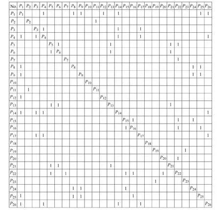
Fig. 2. Disassembly constraint relation DSM of hydraulic forging press

Fig. 3. Disassembly constraint relation weighted DSM of hydraulic forging press
5.2 Decomposition of the disassembly constraint relation weighted DSM of the hydraulic forging press
To construct a disassemblability configuration model for the hydraulic forging press, it is required to decompose the disassembly constraint relation weighted DSM, to form hydraulic forging press configuration modules with external weak coupling and strong internal coupling. The decomposition method provided in section 4.2 (1) is used to decompose DSM completely, to determine configuration modules Q1–Q11represented by coupling matrix blocks, as shown in Fig. 4.
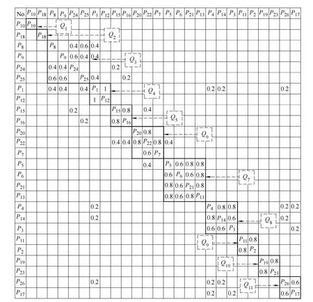
Fig. 4. Decomposition of the disassembly constraint relation weighted DSM of hydraulic forging press
5.3 Tearing of disassembly constraint relation weighted DSM coupling matrix block of hydraulic forging press
Coupling matrix blocks of the disassembly constraint relation weighted DSM of the hydraulic forging press represent modules of the configuration model, and decomposition of DSM makes inter-module disassembly constraint be weak coupling, but the disassembly constraints between components inside modules are strong coupling. The method of in section 4.2(2) is used for tearing operation of coupling matrix blocks to optimize disassembly sequence of components in modules. Taking the matrix blocks Q8in Fig. 4 as an example, the disassembly sensitivity between components are calculated,and the results are shown in Table 2.
The components with a minimum disassembly constraint input and a maximum disassembly constraint output are put to the front rows of the coupling matrix block, so the disassembly sequence of components in Q8should be adjusted to: P3→P14→P4. The disassembly sequence optimization can be achieved through matrix transformation. Similarly, tearing operation is conducted to other coupling matrix blocks. The reorganized disassembly constraint relation weighted DSM of the hydraulic forging press is shown in Fig. 5.

Table 2. Disassembly sensitivity of components in coupling matrix blocks
In the configuration modeling stage of the hydraulic forging press, taking disassemblability between components into consideration, the configuration model is reconstructed by DSM decomposition and tearing, the decomposed weak coupling components P10and P18are used as configuration modules alone, components with a strong coupling are aggregated into configuration modules,existing in the form of matrix blocks(Q3–Q11in Fig. 4), and the disassembly sequence of components inside configuration modules is optimized by tearing operationin Fig. 5), which makes the modules of the configuration model weakly coupled and components in configuration modules strongly coupled, so a disassemblability configuration model of the hydraulic forging press is constructed.

Fig. 5. Tearing of disassembly constraint relation weighted DSM coupling matrix block of hydraulic forging press
6 Conclusions
(1) By analyzing the disassemblability of configurable product, disassembly entropies such as joint type, joint quantity, disassembly path, disassembly accessibility and material compatibility between components are calculated,and an integrated indicator-disassembling degree reflecting the disassemblability of the configurable product is calculated by weighting, based on which, the disassembly constraint relation weighted DSM of the configurable product is constructed.
(2) Through matrix decomposition and tearing operation of the disassembly constraint relation weighted DSM of the configurable product, disassembly constraint relation coupling matrix blocks are formed, and there are strong coupling constraint relations inside blocks and weak coupling constraint relations between blocks, and configuration modules are constructed based on the matrix blocks.
(3) The product disassemblability configuration modeling technology based on disassembly constraint relationship weighted DSM is studied, and the modeling process of disassemblability configuration is analyzed taking the construction of a configuration model of the hydraulic forging press.
[1] WANG Shiwei, TAN jianrong, ZHANG Shuyou, et al. Case-based product configuration and reuse in mass customization[J]. Chinese Journal of Mechanical Engineering, 2004, 17(2): 233–236.
[2] ZHU Yun, CHEN Xinzhao, ZHANG Li, et al. Study on generalized product configuration model based on customer-driven[J]. Chinese Journal of Mechanical Engineering, 2005, 16(13): 1175–1180.
[3] WANG Shiwei, TAN jianrong, ZHANG Shuyou, et al. Product configuration based on generic bill of material[J]. Journal of Computer-aided Design & Computer Graphics, 2004, 16(5): 655–659.
[4] SOININEN T, GELLE E. Dynamic constraint satisfaction in configuration[C]//Proceedings of the AAAI’99 Workshop on Configuration, 1999: 95–100.
[5] SOININEN T, NIEMELA I, TIIHONEN J, et al. Unified configuration knowledge representation using weight constraint rules[C]//Workshop Notes of the ECAI'2000 Configuration Workshop, pages 79–84, Berlin, Germany, August 2000.
[6] SOININEN T, NIEMELA I, TIIHONEN J, et al. Representing configuration knowledge with weight constraint rules[C]//Proceedings of the AAAI Spring 2001 Symposium on Answer Set Programming, pages 195–201, Stanford, USA, March 2001, AAAI Press.
[7] HUANG Liang, GAO Yuan, QIAN Feng, et al. Configuration selection for reconfigurable manufacturing systems by means of characteristic state space[J]. Chinese Journal of Mechanical Engineering, 2011, 24(1): 23–32.
[8] WEI Wei, FENG Yixiong, TAN Jianrong. Product model evolvement and configuration knowledge reuse method[J]. Chinese Journal of Mechanical Engineering, 2009, 22(6): 856–861.
[9] MOK H S, KIM H J, MOON K S. Disassemblability of mechanical parts in automobiles for recycling[J]. Computers and Industrial Engineering, 1996, 33(3–4): 621–624.
[10] DESAI A, MITAL A. Evaluation of disassemblability to enable design for disassembly in mass production[J]. International Journal of Industrial Ergonomics, 2003, 32(4): 265–281.
[11] SODHI R, SONNENBERG M, DAS S. Evaluating the unfastening effort in design for disassembly and service-ability[J]. Journal of Engineering Design, 2004, 15(1): 69–90.
[12] YI H C, PARK Y C, LEE K S. A study on the method of disassembly time evaluation of a product using work factor method[C]//Systems, Man and Cybernetics, 2003. IEEE International Conference on IEEE, 2003, 2: 1753–1759.
[13] GARCÌA MA, LARRÈ A, LÒPEZ B, et al. Reducing the complexity of geometric selective disassembly[C]//Intelligent Robots and Systems, 2000(IROS 2000), Proceedings 2000 IEEE/RSJ International Conference on IEEE, 2000, 2: 1474–1479.
[14] CHUNG C, PENG Q. An integrated approach to selective disassembly sequence planning[J]. Robotics and Computer Integrated Manufacturing, 2005, 21(4–5): 475–485.
[15] SRINIVASAN H, GADH R. A geometric algorithm for single selective disassembly using the wave propagation abstraction[J].Computer Aided Design, 1998, 30(8): 603–613.
[16] ZHANG Xiufen, ZHANG Shuyou. Product cooperative disassembly sequence planning based on branch-and-bound algorithm[J].International Journal of Advanced Manufacturing Technology, 2010,51(9–12): 1139–1147.
[17] SMITH S, SMITH G, CHEN W H, et al. Disassembly sequence structure graphs: An optimal approach for multiple-target selective disassembly sequence planning[J]. Advanced Engineering Informatics, 2012, 26(2): 306–316.
[18] BEHDAD S, THURSTON D. Disassembly and reassembly sequence planning tradeoffs under uncertainty for product maintenance[J]. Journal of Mechanical Design, 2012, 134(4):041011.
[19] SUGA T, SANESHIGE K, FIUJIMOTO J. Quantitative disassembly evaluation[C]//Proceedings of the 1996 IEEE International Symposium on Electronics and the Environment, Dallas, 6–8 May,1996: 19–24.
[20] SUGA T, HOSODA N. Active disassembly and reversible interconnection[C]//Proceedings of the 2000 IEEE International Symposium on Electronics and the Environment, San Francisco, CA,8–10 May, 2000: 330–334.
[21] SMITH J. A multiple viewpoint modular design methodology[D].Glasgow, UK: University of Strathclyde, 2002.
[22] YASSINE A, FALKENBUEG D, CHELST K. Engineering design management: an information structure approach[J]. International Journal of Product ion Research, 1999, 37(13): 2957–2975.
 Chinese Journal of Mechanical Engineering2014年3期
- Chinese Journal of Mechanical Engineering的其它文章
- Theoretical Analysis and Experimental Verification on Valve-less Piezoelectric Pump with Hemisphere-segment Bluff-body
- Carbody Structural Lightweighting Based on Implicit Parameterized Model
- Prediction-based Manufacturing Center Self-adaptive Demand Side Energy Optimization in Cyber Physical Systems
- Effectiveness of a Passive-active Vibration Isolation System with Actuator Constraints
- Numerical Simulation and Analysis of Power Consumption and Metzner-Otto Constant for Impeller of 6PBT
- Proceeding of Human Exoskeleton Technology and Discussions on Future Research