Analysis of parameter estimation using the sampling-type algorithm of discrete fractional Fourier transform
Bing DENG*,Jun-bao LUAN,Shi-qi CUI
Department of Electronic and Information Engineering,Naval Aeronautical and Astronautical University,Yantai 264001,Shandong,China
Analysis of parameter estimation using the sampling-type algorithm of discrete fractional Fourier transform
Bing DENG*,Jun-bao LUAN,Shi-qi CUI
Department of Electronic and Information Engineering,Naval Aeronautical and Astronautical University,Yantai 264001,Shandong,China
Parameter estimation is analyzed using two kinds of common sampling-type DFRFT(discrete fractional Fourier transform)algorithm.A model of parameter estimation is established.The factors which infuence estimation accuracy are analyzed.And the simulation is made to verify the conclusions.From the theoretic analysis and simulation verifcation,it can be drawn that,for the estimation of chirp-rate and initial frequency,Pei's method[10]is more suitable if the absolute value of chirp-rate is small relatively;Ozaktas'method[9]is more suitable if the absolute value of chirp-rate is large relatively;and the two methods are both workable if the absolute value of chirp-rate is moderate.The scope of moderate chirp-rate can be approximately determined as[40 Hz/s,110 Hz/s].
Parameter estimation;Chirp signal;Sampling-type DFRFT
1.Introduction
With the development of some related research,fractional Fourier transform(FRFT)has been widely used for signal analysis and reconstruction,signal detection and parameter estimation,flter in the transform-domain,voice analysis, image processing,neural network,mode recognition,array signal processing and radar,communication,sonar[1-7].The key factor that promotes the application of FRFT is the appearance of fast algorithm which computation burden is as considerable as FFT[8].
Now,there are three kinds of algorithm for discrete fractional Fourier transform(DFRFT),namely sampling-type DFRFT algorithm,eigen-decomposition DFRFT algorithm, and linear-weighting DFRFT algorithm.The sampling-type DFRFT algorithm becomes the most popular algorithm by mapping N sampling values of the original function to N sampling values of its FRFT,which not only provides a perfect value accuracy in approaching continuous FRFT but also its calculation complexity is decreased to O(N log N).The sampling-type DFRFTalgorithm includes two algorithms with mostly same performance,namely Ozaktas'method[9]and Pei's method[10].Ozaktas'method has been used widely,but it requires dimensional normalization to simplify deduction. Compared with Ozaktas'method,Pei's method takes sample input and output values directly,keeping the transformation reversible by limiting input-output sample interval so that the method is more understandable[10].How to choose the two methods in practical application?Since FRFT can be regarded as chirp decomposition,and it can be used to process chirp signals,the two methods are theoretically analyzed and some simulations are made using parameter estimation of chirp signal in the paper.//dx.doi.org/10.1016/j.dt.2014.06.011
2214-9147/Copyright©2014,China Ordnance Society.Production and hosting by Elsevier B.V.All rights reserved.
2.FRFT
2.1.Defnition
The FRFT is defned as

where α represents the transform angle;Kα(t,u)represents the transform kernel;andndemotesan integer.(In this paper,α≠nπ).
2.2.Discrete algorithm
2.2.1.Ozaktas'method
Ozaktas'method is frstly to decompose the complex integral transformation of FRFT into several simple calculation processes;a discrete convolution expression can be got after two steps of discretization,so that FFT can be used to calculate FRFT.Therefore,this method is as fast as FFT. However,the originalsignalrequiresthe dimensional normalization in this method.
2.2.1.1.Dimensional normalization.It is assumed that a signal is compact in both time domain and frequency domain, thus it is limited between[-Δt/2,Δt/2]in the time domain, and between [-Δf/2,Δf/2]in the frequency domain. Dimensional normalization is the method that makes both the time and frequency domains dimensionless.
Firstly,the scaling factorSis defned with time unit.Secondly,a new scaling coordinates is defned:w=t/S,v=f·S.the new coordinate system(w,v)is dimensionless.Ifthe region lengthsdomains equal the dimensionless quantityThat is to say,the two regions are both normalized to[-Δx/2,Δx/2].Finally,the normalized signal is sampled according to the sampling theorem,and the sampling interval is 1/Δx.This means that FRFT derivedfromtheOzaktas'methodistheresultafterdimensional normalization.However,the signal is not normalized in fact,so the result should be revised in the applications.
2.2.1.2.Algorithm.According to Eq.(1),FRFT can be divided into the three steps


Becausex(t)is the signal after dimensional normalization, its width in all fractional Fourier domains is limited between[-Δx/2,Δx/2].When the transform angle is limited in π/4≤|α|≤3π/4, the highest frequency ofg(t) is 0.5(1+|cot α|)Δx≤Δx,so the sampling interval is determined as 1/(2Δx).After deduction,we can conclude that the whole process can be expressed as

where XαrepresentsN×1 column vector of discrete sample fromXα(u);x representsN×1 column vector of discrete sample fromx(t);Fα=DKαJ,D represents double interpolation matrix and J represents double decimation matrix [9],

Although the deduction above can be established only when π/4≤|α|≤3π/4,the angle range can be extended to 0≤|α|≤π/4 or 3π/4≤|α|≤π if the rotating additivity of FRFT is used.
2.2.2.Pei's method
Unlike Ozaktas'method,Pei's method samples the input variable and output variable directly,which keeps the transform reversibility by limiting the input and output sample intervals.This method is simple and fast,for its need of only twice chirp product and one FFT.However,its disadvantage is complacency with rotating additivity partially.
From variable substitution,Eq.(1)can be expressed as

Firstly,the input functionx(t)with the sample interval Δtand the output functionXα(u)with the sample interval Δuare sampled,respectively.We obtain

Substituting Eq.(7)into Eq.(8),we have

After deduction,the conclusion can be drawn that (1)for sin α>0

(2)for sin α<0
AndM≥Nand Δt·Δu=should be satisfed.

3.Theoretical analysis
3.1.Analysis of parameter estimation model
According to the algorithms in Section 1,Ozaktas'method is to divide FRFT into three steps,and uses dimensional normalization and double interpolation operation to realize dimension unifcation and meet Shannon sampling theorem.In contrast, Pei'smethoddiscretizestheinputandoutputsignalsdirectlyand determines thesamplinginterval based on reversibility to obtain DFRFT.In the discrete computation,Ozaktas'method only needstheinputsignalandthetransformanglewhilePei'smethod needs the sampling interval and the sample number of input and output signals in addition.It leads to some differences in parameter estimation accuracy of chirp signals.
The basic idea of chirp signal detection and parameter estimation using FRFT is as follows[11,12]:since chirp signals present different energy concentration performances in different fractional Fourier domains,the FRFT of observed signal versus the transform angle α is calculated to obtain twodimensional distribution of signal energy on the plane(α,u); then two-dimensional search of peak values proceeds according to the determined threshold.
Let the chirp signals(t)be

After sampling,it becomes

wheren=1,2,…,N,(N-1)Ts=Td;Tdis the sampling duration;andTsis the sampling period.We proceed DFRFT with the transform angle step αsin[-π/2,π/2]to form twodimensional distribution of signal energy on the plane(α,u). The peak coordinatescan be determined as(︿k,︿m),︿m∈[1,N],︿k∈[1,Nα],Nα=[π/αs]floor+1 after the twodimensional search of peak values.The symbol[·]floorindicates round-off,and(︿m,︿k)depends on the parameters μ andf0.
Next,we take the chirp-rate μ and the initial frequencyf0for example to analyze the difference between these two methods.According to the dimensional normalization factor referred in Refs.[13,14],the estimation of μ andf0in Ozaktas' method is as follows.
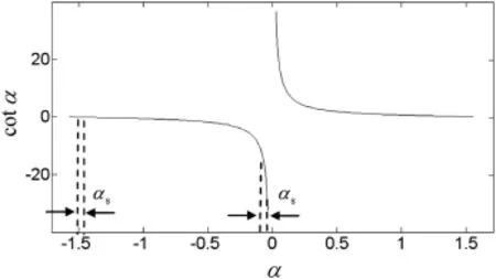
Fig.1.Peak searching with the determined step.

wherefs=1/Ts,

Pei's method can be used to obtain the peak coordinates)in the same way and the estimation of μ andf0is as follows:

where︿α is defned by Eq.(15),

From Eqs.(1)and(7),we can fnd that Ozaktas'method uses frequency as the dimension unit while Pei's method uses angular frequency,so there is the additional product factor 1/ 2π in Eq.(16).
3.2.Analysis of parameter estimation accuracy
Comparing Eqs.(14)and(16),we can fnd that the peak position obtained by Ozaktas'method has some relations not only with μ andf0which determine︿mand︿k,but also with the dimensional normalization factorfs/Td.
3.2.1.Estimation accuracy of chirp-rate
For the estimation of chirp-rate μ,the two methods both search the peak versus the transform angle α with the determined step αs.In fact,they both search the peak versus cot α,as shown in Fig.1.It can be seen from Fig.1 that the change of cot α is slow when the peak appears about α=±π/2 while the change is cliffy when the peak appears about α=0.
In other words,with the determined step αsthe search of chirp-rate is fne around α=±π/2 but rough around α=0. This means that the estimation accuracy of chirp-rate when the peak appears about α=±π/2 is higher than that it appears about α=0.
According to the relationship of FRFT and time-frequency distribution[15],we can fnd that the transform angle for the peak is more close to±π/2 when the absolute value of chirprate to be estimated is relatively small.
For the search versus cot α,Ozaktas'method uses revised chirp-rate,μ⌒=μ·Td/fs,while the real chirp-rate μ is used in Pei's method.Then we can draw the conclusion as follows:
1)Pei's method is more suitable if the absolute value of chirprate is relatively small;
2)Ozaktas'method is more suitable if the absolute value of chirp-rate is relatively large,andfsandTdcan be changed to improve the estimation accuracy.
Further,the relations between them are analyzed in three kinds of cases.
We know that Pei's method is more suitable in this case from the above analysis.However,If the absolute value of revised chirp-rate is decreased by changingfsandTd,Ozaktas' method is superior to Pei's method.According to the sampling theory,there certainly existsfsandTdthat meetfs>Td,which could leads to μ⌒<μ.That is to say,Ozaktas'method seems superior to Pei's method through the choice offsandTdeven if|is small enough.
In order to makefs>Td,we need to reduceTdor raisefs. Due to the resolution of chirp-rate being proportionate to the square ofTd,the decrease inTdprobably leads to the sampled signal segment similar to the single frequency signal segment for smallIn other words,this case maybe results in that|μ|is too small to be resolved,which goes against parameter estimation.There is no relation between the chirp-rate resolution andfs,thus the chirp-rate resolution will| no|t be affected whenfsis increased.However,due to smallthe search scope of transform angle lies in the region where the change of cot α is slow.The beneft is negligible if the peak moves towards-π/2,which brings the increase of data amount and the damage of real-time requirement.Simulation 1 in Section 4 verifes the above-mentioned analysis.
According to the conventional Shannon sampling theorem, the sampling frequency has to be satisfed as follows

Let μ>0 andf0=0,we can obtain
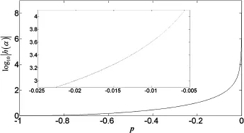
Fig.2.The logarithmic curve of|h(α)|.
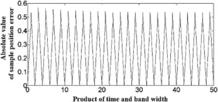
Fig.3.The curve of the absolute value of peak position error with the optimal transform angle(fs=1 KHz,Td=1 s).

Since the peak search via cot α corresponds to the peak search versus μ⌒=μ·Td/fsfor Ozaktas'method,and

namely,

obviously we can obtain

Eq.(22)shows that αmlies in the slowly changing section near-π/2.
The analysis above is done with the condition of μ>0, however the same conclusion can be drawn for μ<0.Thus the transform angle of FRFT,which corresponds to the revised chirp-rate,can be adjusted within the fat interval to keep the satisfying accuracy through dimensional normalization when|is large.
In this case,it is suitable for either Ozaktas'method or Pei's method.Then how do we determine the scope of this intermediate interval?
From Fig.1,we can fnd that cot α changes slowly within some certain interval near-π/2.In other words,the estimation accuracy of parameter is higher in this interval.However, cot α changes sharply when α is beyond this interval.Thus, this interval can be used as the symbol to determine whetheris large enough.The derivative of cot α is

The logarithm curve of|h(α)|is shown in Fig.2,where the horizontal coordinate expressesp=α/
It is obvious that the curve changes slowly when|h(α)|is less than 103,and increases sharply when it is larger than 104. So we can determine the intermediate interval based on the above-mentioned phenomenon.For log10|h(α)|=3,pis about -0.02,and for log10|h(α)|=4,pis about-0.006.Since

the intermediate interval can be determined as[40 Hz/s, 110 Hz/s].
According to the symmetry of cot α,we can draw the same conclusion for α∈(0,π/2).Thus,the repeated analysis is omitted.
3.2.2.Estimation accuracy of initial frequency
Now,the estimation of the initial frequencyf0is analyzed. Substituting︿uinto Eq.(14),we can get

Substituting︿upinto Eq.(16),we have

When︿mis changed by a unit interval,from Eq.(25)the estimation value is changed by

and from Eq.(26)the estimation value correspondingly is changed by


Table 1The estimation errors of chirp-rate in simulation 1.
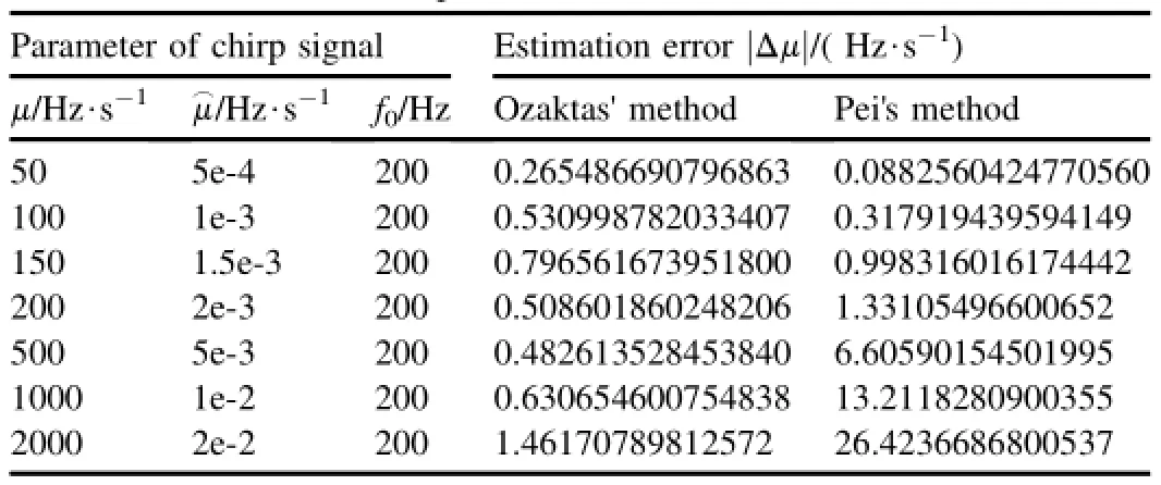
Table 2The estimation errors of chirp-rate in simulation 2.
2.2.3.Fractional Fourier spectral leakage
Since DFRFT is the discrete sampling of continuous FRFT spectrum,the peak position,resulted from the search of DFRFT,probably is not the theoretical peak position of continuous FRFT spectrum,which is called the fractional Fourier spectral leakage[16,17].The above-mentioned factor will bring the estimation error.
The search accuracy of FRFT angle is related with the search step,for the fxed step for searching.Assuming that the correct FRFT angle αTjust right lies in the searching set of FRFT angle,then it can be assured that the peak position resulted from searching DFRFT is just the peak position of continuous FRFT spectrum as long as the following formula holds.


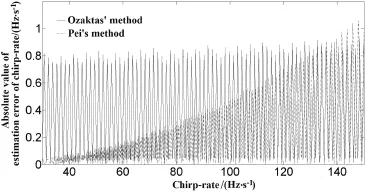
Fig.4.The estimation error of chirp-rate in Simulation 3.
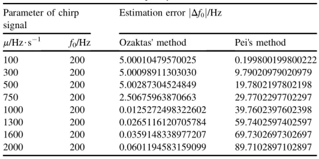
Table 3The estimation errors of initial frequency in simulation 4.
For the parameter estimation of chirp signal,the estimation accuracy will fuctuate with the different products of time and band width due to the change of sampling position of the peak in the condition of the same fs,Tdand search step.
4.Simulation
4.1.Simulation 1
Set fs=100 Hz,Td=1 s,αs=0.00001×π/2,f0=0 Hz, μ∈{0.5 Hz/s,1 Hz/s,5 Hz/s},and fsis increased to 1 KHz or Tdis decreased to 0.1 s.The simulation results are listed in Table 1.The conclusion can be drawn as follows:a)For Ozaktas'method,what we search is the revised chirp-rate so that Tdis too small to distinguish and the estimated value of chirp-rate is approximately 0.Increasing fscan not improve the performance effectively;b)Pei's method is almost not affected by Tdand fs,and its estimation accuracy is obviously superior to that of Ozaktas'method.
4.2.Simulation 2
Set fs=10 kHz,Td=0.1 s,αs=0.00001× π/2, f0=200 Hz,and μ is changed from 50 Hz/s to 2 KHz/s.The simulation results are listed in Table 2.We can draw the conclusion that,in Pei's method,the larger the chirp-rate is,the higher the estimate error is;on the contrary,in Ozaktas' method,the error is relatively stable and smaller than that from Pei's method.
4.3.Simulation 3
Set fs=10 KHz,Td=0.1 s,αs=0.00001× π/2, f0=100 Hz,and μ is changed from 30 Hz/s to 150 Hz/s with the step of 0.1 Hz/s.The simulation results are shown in Fig.4. The conclusion can be drawn as follows:a)at the beginning, Pei's method is more accurate than Ozaktas'method;as the chirp-rate raise,the estimation errors of two methods are approximately identical,and Ozaktas'method is better than Pei's method in accuracy when the chirp-rate is beyond 130 Hz/s;b)the estimation accuracy of both the two methods presents fuctuation due to the fractional Fourier spectral leakage.
4.4.Simulation 4
Set fs=10 KHz,Td=0.1 s,αs=0.000001× π/2, f0=200 Hz,and μ is changed from 100 Hz/s to 2 KHz/s.The estimation results of initial frequency are listed in Table 3.We can fnd that:a)Pei's method is better than Ozaktas'method when the chirp-rate estimation accuracy of the former is near to or better than the latter;b)the estimation error of chirp-rate of Pei's method rises with the increase in chirp-rate,which leads to the increase in the estimation error of initial frequency.This means that Pei's method is worse than Ozaktas' method with the gradual increase in chirp-rate.
5.Conclusions
In this paper,two kinds of sampling-type DFRFT are analyzed through parameter estimation,and the conclusions are drawn as follows:
1)|μ|∈[40 Hz/s,110 Hz/s]can be determined as the inter
mediate interval.In this range,Pei's method has the same parameter estimation accuracy as Ozaktas'method.The usageofthesetwomethodsshouldbechosenbysomeother factors,such as computation burden,not only the accuracy.
2)When|μ|is small(smaller than 40 Hz/s),it is better to use Pei's method.Furthermore,Ozaktas'method can not increase its accuracy by increasing fsor decreasing Td. About the two operations,increasing fsgains little beneft with the cost of the increase of data mount;decreasing Tdmaybe leads to the lose of resolution.
3)When|μ|is large enough(larger than 110 Hz/s),Ozaktas'
method can obtain higher accuracy through dimensional normalization.And the estimation accuracy of Ozaktas' method can be kept high only if the sampling theory is met.
4)Theoretically Pei's method is better than Ozaktas'method for estimation of initial frequency,but the increase in estimation error of chirp-rate will bring the synchronized magnifcation of estimation error of initial frequency. Thus,Ozaktas'method is more suitable for the united estimation of chirp-rate and initial frequency when|μ|is large enough.
Acknowledgment
The authors would like to thank the National Natural Science Foundation of China(60902054);China Postdoctoral Science Foundation(201003758,20090460114)and“Taishan Scholars”Special Foundation of Shandong Province for the support.
[1]Sejdic E,Djurovic I,Stankovic L.Fractional Fourier transform as a signal processing tool:an overview of recent developments.Signal Process 2011;91:1351-69.
[2]Tao Ran,Deng Bing,Wang Yue.Research progress of the fractional fourier transform in signal processing.Sci China Ser F Info Sci 2006;49(1):1-25.
[3]Narayanan VA,Prabhu KMM.The fractional Fourier transform:theory, implementation and error analysis.Microprocess Microsystems 2003;27:511-21.
[4]Ozaktas HM,Kutay MA,Zalevsky Z.The fractional Fourier transform with applications in optics and signal processing.New York,NY:John Wiley&Sons;2001.
[5]Tao Ran,Deng Bing,Wang Yue.Fractional Fourier transform and its applications.Beijing:Tsinghua University Press;2009.
[6]Xuemei Li.Research on estimation of time delay based on the fractional Fourier transform.Beijing:Beijing Institute of Technology;2010.
[7]El-Mashed MG,Dessouky MI,El-Kordy M,Zahran O,Abd El-Samie FE.Target image enhancement in radar imaging using fractional Fourier transform.Sens Imaging Int J 2012;13(1):37-53.
[8]Tao Ran,Zhang Feng,Wang Yue.Research progress on discretization of fractional Fourier transform. Sci China Ser F Info Sci 2008;51(7):859-80.
[9]Ozaktas HM,Arikan O,Kutay MA,Bozdagt G.Digital computation of the fractional Fourier transform.IEEE Trans SignalProcess 1996;44(9):2141-50.
[10]Pei Soo-Chang,Ding Jian-Jiun.Closed-form discrete fractional and affne Fourier transform. IEEE Trans Signal Process 2000;48(5):1338-53.
[11]Lin Qi,Tao Ran,Si-Yong Zhou,Wang Yue.Detection and parameter estimation of multicomponent LFM signal based on the fractional Fourier transform.Sci China Ser F Info Sci 2004;47(2):184-98.
[12]Hongkai Wei,Pingbo Wang,Zhiming Cai,Wanjun Yao.Study of algorithm for extremum seeking in the fractional Fourier transform.Acta Electron Sin 2010;38(12):2949-52.
[13]Zhao Xing-hao,Deng Bing,Tao Ran.Dimensional normalization in the digital computation of the fractional Fourier transform.Trans Beijing Inst Technol 2005;25(4):360-4.
[14]Liu Feng,Xu Hui-fa,Tao Ran.Selection of dimensional normalization parameters in fractionalFouriertransform.SystEng Electron 2011;33(2):237-41.
[15]Pei Soo-Chang,Ding Jian-Jiun.Relations between gabor transforms and fractional Fourier transforms and their applications for signal processing. IEEE Trans Signal Process 2007;55(10):4839-50.
[16]Deng Bing,Tao Ran,Qu Chang-wen.Analysis of the shading between multicomponent chirp signals in the fractional Fourier domain.Acta Electron Sin 2007;35(6):1094-8.
[17]Hongzhong Zhao,Qiang Fu.Performance analysis of acceleration resolution for radar signal. Sci China Ser E Technol Sci 2003;33(7):638-46.
Received 1 March 2014;revised 24 June 2014;accepted 25 June 2014 Available online 24 July 2014
*Corresponding author.
E-mail address:dengbing@bit.edu.cn(B.DENG).
Peer review under responsibility of China Ordnance Society.
http:
Copyright©2014,China Ordnance Society.Production and hosting by Elsevier B.V.All rights reserved.
- Defence Technology的其它文章
- Nitrogen analogs of TEX-A computational study
- Neural network modeling to evaluate the dynamic fow stress of high strength armor steels under high strain rate compression
- Scale-up synthesis and characterization of 2,6-diamino-3,5-dinitropyrazine-1-oxide
- Experiment and simulation of launching process of a small-diameter steel cartridge case
- Reliability sensitivity analysis based on multi-hyperplane combination method
- Feasibility of surface-coated friction stir welding tools to join AISI 304 grade austenitic stainless steel

