Experiment and simulation of launching process of a small-diameter steel cartridge case
Han-dong ZHAO,Jia-qing XIE*,Zhi-peng LI,Hui-suo ZHANG
North University of China,Taiyuan 030051,Shanxi,China
Experiment and simulation of launching process of a small-diameter steel cartridge case
Han-dong ZHAO,Jia-qing XIE*,Zhi-peng LI,Hui-suo ZHANG
North University of China,Taiyuan 030051,Shanxi,China
In order to explore the rules of the deformation force during the launching of a small-diameter steel cartridge,the semi-closed bomb test method is used to test the greatest strains on chamber outer wall under the different chamber pressures.The pressure curves of cartridge chamber are measured in experiment,and the tensile test data of cartridge are loaded into the numerical calculation to compare with the experimental data.The conclusion was obtained that the calculated results match better with the experimental results by considering strain rate bilinear kinematic hardening material constitutive model.The forces on the various parts of the cartridge during launching and their deformation rules are achieved,in which the equivalent plastic strain decreases and the cylinder ring withstands the maximum equivalent stress when the cartridge case clings to the bore from the mouth to the bottom.
Steel cartridge case;Semi-closed bomb;Numerical calculation;Constitutive model
1.Introduction
Since the deformation of each part of cartridge case during the fring process is very complex,it is usually diffcult to reproduce the interaction between cartridge case and chamber.The semi-closed bomb test is an important means to study the problem.However,because of technical limitations,the method does not intuitively obtain the forces and deformations of various parts of the cartridge in the chamber.A feasible method is to calculate indirectly the deformation of cartridge case by testing the deformation of chamber outer wall.In recent years,a lot of work has been done for the study of cartridge launching process.Sun et al. [2]proposed an experimental platform for the mechanism research on the gun launching dynamics and formulated a dynamics model of the simulated gun recoil based on the processes of hydraulic buffering and pressure discharge reduction and the interior ballistics equations.Nassehi et al. [1]established a fnite-element model of combined free/ porous fow regimes to simulate fow through pleated cartridge flters.It has been demonstrated that the model presents a cost effective,robust and reliable design tool to enable engineers to appraise the operation of such flters.Shi et al.[3]proposed an inverse method to determine material parameters.The method uses a fnite element model and measures the resonance frequencies as a non-destructive technique to characterize the materials.
Based on the above analysis,this paper used a combination of experiment and computer numerical simulation.The chamber pressure curve of cartridge bore and the tensile test data of steel cartridge case were both used in numerical calculation.The best way was determined to characterize the stress-strain conditions of cartridge case in the launching process of gun by comparing the numerical calculation and test results of the cartridge outer wall deformation.
2.Deformation of cartridge case in chamber
With the change of pressure in the chamber,the cartridge case is deformed and displaced.The changing process of pressure is described in terms of the following four stages.The frst stage is to start from the radial deformation of cartridge chamber to the elimination of initial clearance,which is characterized by the deformation of the cartridge case.With the increase in pressure in the chamber,the elastic deformation begins.When the force exceeds the elastic limit,the cartridge case is plastically deformed and its material is strengthened. The results of radial expansion and deformation of the cartridge case are to eliminate the initial radial clearance so that the cartridge case wall contacts the chamber wall,which plays a role in sealing the powder gas.The second stage is from the elimination of initial clearance to the appearance of maximum pressure in cartridge chamber.The maximum tangential deformations of cylinder case and chamber result from the maximum chamber pressure.Cartridge chamber is elastically deformed,and the cartridge case is elastically and plastically deformed.In this stage,the cartridge case is subjected to a complex force.In particular,the stress state of the cartridge case base is extremely complex.The third stage is from the drop in bore pressure to the ceasing of residual effect.In the stage,with the drop in bore pressure,the chamber wall is restored to its initial position.Due to the plastic and elastic deformations of cartridge case,it can't be restored to its original position.At the end of the launch,a clearance may exist between the cartridge case and the chamber,it may still be in the interference condition.The fourth stage is the ceasing of residual effect to the bore pressure dropping to atmospheric pressure.For general-purpose artillery,the ejection of cartridge case is carried out during this period.At that time,the chamber wall returns to the initial position,the elastic recovery of the cartridge case wall is ended,and the residual deformation due to plastic deformation keeps it from returning to the initial position[1].
3.Launch test of cartridge case in bore
3.1.Principle of test setup
The test setup consists of fring mechanism,chamber, pressure gage,outgassing device,strain measuring device, pressure relief faps,plug and so on.Before the test,a cartridge case flled with a certain amount of charge is loaded into the cartridge chamber,and the fring mechanism is screwed on. Make sure that the surface of the cartridge case base is coincided with the front face of fring mechanism,and the mouth of the cartridge case is coincided with the neck bush of chamber.The detailed assemblage of the test setup is shown in Fig.1.After the commissioning of test setup,the fring device is pulled,and the cartridge case primers ignite the gunpowder. A mass of gas is instantaneously released when the gunpowder burns,and the in-bore pressure rises rapidly.The pressure breaks through the aluminum slice when it exceeds the maximum shear stress of aluminum slice.At this time,the inbore pressure is decreased to atmospheric pressure.The pressure measuring device is used to record the change process of pressure in the bore.The strain measuring device which are affxed to the outer wall of the chamber are used to record the strain changes at that point.Fig.2 shows the installed physical test setup.
3.2.Test result
Single-base powder 6/7 was chosen as a propellant,and three launch tests of cartridge cases with different charge masses were carried out.Table 1 shows the maximum chamber pressure and the surface strain data of chamber.Fig.3 shows the measured in-bore pressure curves.The curves will be used for subsequent numerical calculations.
4.Numerical calculation
The numerical calculation model is established based on the following basic assumptions.
(1)The shape of cartridge case is ideally axisymmetric cylindrical.
(2)The material is homogeneously and isotropically distributed.
(3)The chamber pressure which the interior wall of cartridge casewithstandsatthesametimeisconstantanduniform[4].4.1.Selection of material constitutive modelANSYS/LS-DYNA dynamics analysis software was used in calculation.LS-DYNA has more than 150 kinds of material constructive models.The material parameters are quite different.As mentioned before,the elastic model was chosen to simulate the actual launching process of chamber only atthe stage of elastic deformation.Therefore,the software itself provides an isotropic hardening bilinear kinematic constitutive model to simulate the launching process of cartridge in chamber.The model is a mixed isotropic and kinematic hardening model,which selects isotropic or kinematic hardening by adjusting the hardening parameter β between 0 (only kinematic hardening)and 1 (only isotropic hardening).

Fig.1.Assembly diagram of test setup for fring the cartridge case in bore.
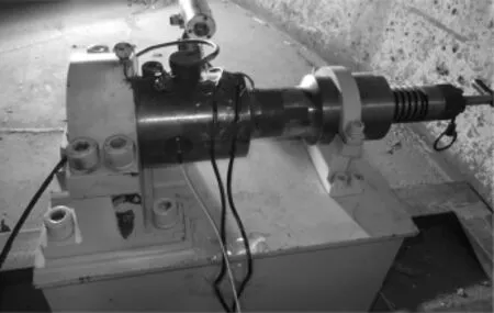
Fig.2.Physical photo of test setup for fring the cartridge case in bore.
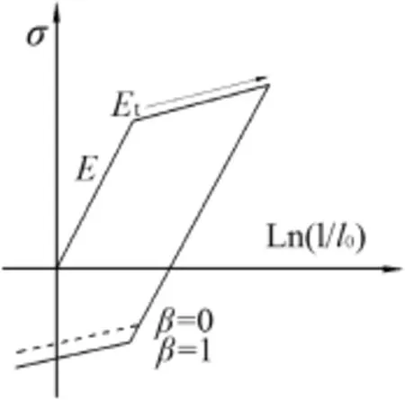
Fig.4.PLASTIC_KINEMATIC model.


Table 1Test results.
The yield stress was set before the simulation by considering the damage of structural elements,the failure strain was set by considering whether the failure element quits working, and the Cowper-Symonds model was used for the effect of strain rate.A factor associated with the strain rate represents the yield stress.As shown in Fig.4,the default means that the effect of strain rate is not considered in calculation.In Eq.(1), the default strain rate and strain rate are considered.In calculation,the strain effect parametersCandpare taken as 40.5 and 5,respectively[5].
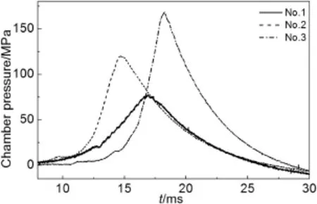
Fig.3.Chamber pressure curves measured in the case of different charge mass.
where σ0is the initial yield stress;Epis plastic hardening modulusEp=EtanE/E-Etan,whereEis the elastic modulus,Etanis the tangent modulus;andCandpare the strain effect parameters.
4.2.Mechanical properties of materials
The material of launching device is gun-steel,the elastic modulus is 210 GPa,and Poisson's ratio is 0.3.The parameters of mechanical properties of parts in the cartridge case are listed in Table 2.
5.Result analysis
5.1.Effect of strain rate on numerical results
The chamber pressures were calculated without and with considering the strain rate of material,respectively.The calculated chamber pressure results are compared with the test data,as shown in Fig.5.The numerical calculation results which were obtained at low chamber pressure are in good agreement with test data.With the increase in chamber pressure,the numerical calculation result has a great deviation relative to the test result without considering the strain rate, and with the further increase in chamber pressure,the trend is more obvious.
The reason for this is that the relative charge density of propellant is low at low test chamber pressure,and the burning speed of gunpowder is slow,too.A delayed yield due tomaterial rate is not too obvious,therefore,the results are not very different from each other.With the increase in charge,the bore pressure curve rises rapidly,the strain rate increases in the launching process of cartridge,and the effect of material rate is obvious[6].The result shows that the failure model considering the effect of material rate can be used accurately to simulate the launching process of cartridge case in bore,and the effect of material rate in the launching process should not be ignored.
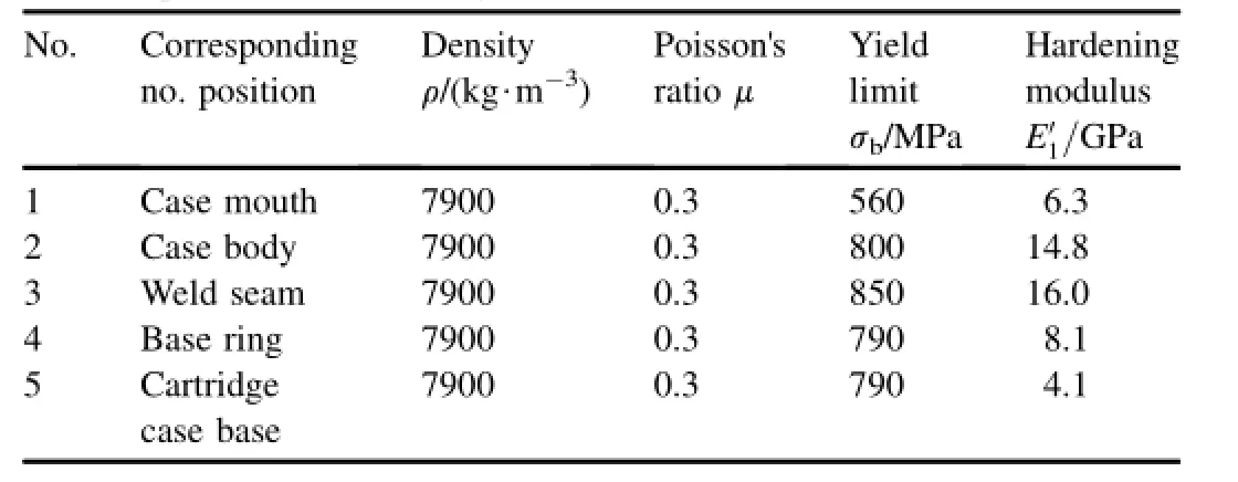
Table 2Material parameters of cartridge case.
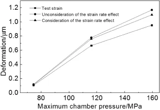
Fig.5.The comparison of different material models.
5.2.Analysis of cartridge deformation
The launching process of cartridge case in bore,which considers the effect of material rate,was analyzed.Since the chamber pressure of cartridge case is high,the numerical result of maximum chamber pressure(174.9 MPa)is closer to the actual chamber pressure.Table 3 lists the forces applied on various parts and the deformation of cartridge case during launch,with the maximum chamber pressure of 174.9 MPa.It can be seen from Table 3 that the force in the axial direction of cartridge case is mainly applied on the ring of cartridge base, followed by the occurrence of the cylinder is connected to the bottom ring section of a ring weld.It follows that the base is the most damageable component of the cartridge case.The tensile strength of welds should be enhanced to prevent them cracking.
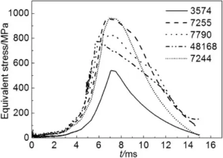
Fig.6.Unit stress curves of different numbers.
Because of the initial gap between the interior wall of chamber wall and the outer wall of cartridge case,the maximum plastic deformation of the cartridge case occurs before the maximum pressure in chamber is reached,and the equivalent stress increases rapidly.When the radial deformation of the cartridge case is bigger than the initial gap, the cartridge case clings to the interior wall of cartridge chamber.After slinging,the cartridge case and the cartridge chamber tend to radially expand,cartridges achieve maximum stress.Then the stress of the cartridge case begins to slowly reduce,and declines rapidly at the maximum chamber pressure point[7].
It can be seen from Fig.6 that the stress on each part of cartridge case increases rapidly with the increase in cartridge chamber pressure.The cartridge case undergoes a rapid and large deformation due to the presence of initial gap.As the chamber pressure continues to rise,the radial deformation continues after the cartridge case clings to the chamber tightly. At this time,the deformation of cartridge case is dominated by the plastic strain,and a recoverable elastic deformation occurs in the chamber.With the increase in stress,the plastic hardening and elastic deformation of chamber lead to the maximum equivalent stress.After the maximum bore pressure is achieved,the reverse loading takes place on the outer wall of the cartridge case,which from the elastic recovery strain of chamber.In Fig.6,the reverse loading can be refected by the short smooth transition sections on the descending parts of equivalent stress curves of Unit 48,168,7790 and 7255.
As shown in Fig.7,the change tendency of the cartridge equivalent plastic strain is that it decreases from the mouth to the base.The biggest plastic deformation occurs at the month to insure a good obturating role,reducing the erosion on the cartridge chamber by gunpowder gases and extending barrel life.However,in order to make the full combustion of gunpowder by improving the bore pressure,it needs to have a certain bullet pull strength,which in turn requires the mouthwith certain strength.The actual production optimization goals need to weigh this contradiction[8].

Table 3The cartridge unit dynamic data in each part.
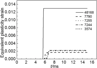
Fig.7.Equivalent plastic strains.
6.Conclusions
Semi-closed bomb tests and computer numerical calculation method were both used in this paper.A reasonable material constitutive model was chosen,and the launching process at the chamber pressure of 174.9 MPa was analyzed. The conclusions have been drawn as follows.
1)The kinematic hardening constitutive model,which considers the effect of linear material rate,in LS-DYNA explicit dynamic analysis software can be used to refect the stresses and deformations of cartridge parts during launch more reasonably.
2)The cartridge case clings to the bore from the mouth to the base and the equivalent plastic strain decreases gradually during launch.The cartridge material should not only have good ductility but also have certain strength to achieve the desired bullet pull strength.
[1]Nassehi V,Hanspal NS,Waghode AN,Ruziwa WR,Wakeman RJ.Finiteelement modelling of combined free/porous fow regimes:simulation of fow through pleated cartridge flters. Chem Eng Sci 2005;60(4):995-1006.
[2]Sun Quan-zhao,Yang Guo-lai,Yi Qun-zhi,Yuan Ren-shu,Ge Jian-li. Dynamics of gun simulated recoil system with semi-closed bomb.J Nanjing Univ Sci Technol 2013;37(5):687-91.
[3]Yin-ming Shi,Hugo Sol,Hong Xing-hua.Material parameter identifcation ofsandwich beamsby an inverse method.JSound Vib 2006;290(3):1234-55.
[4]Cul Yan-hua,Zhao Han-dong,Zhang Hui-suo,Xin Chun-hong.Variation law of extraction force of cannon cartridge cases with tangent modulus of materials.Foundry Technol 2012;33(7):777-9.
[5]Hernandez C,Maranon A,Ashcroft IA,Casas-Rodriguez JP.A computational determination of the Cowper-Symonds parameters from a single Taylor test.Appl Math Model 2013;37(7):4698-708.
[6]Zhuo-ming LI.Deformation analysis of light cartridge in the conditions of high temperature and high pressure.Nanjing:Nanjing University of Science&Technology;2008.
[7]Sakarya U,Topcu O,Leloqlu UM,Soysal M,Tunali E.Automated region segmentation on cartridge case base. Forensic Sci Int 2012;222(1-3):277-87.
[8]Hollis Bruce W.Assay of circulating 1,25-dihydroxyvitamin D involving a novel single-cartridge extraction and purifcation procedure.Clin Chem 1986;32(11):2060-3.
Received 5 December 2013;revised 29 June 2014;accepted 3 July 2014 Available online 29 August 2014
*Corresponding author.
E-mail addresses:nhn206@sina.com,jiaqingnuli@163.com(J.Q.XIE).
Peer review under responsibility of China Ordnance Society.
http://dx.doi.org/10.1016/j.dt.2014.07.009
2214-9147/Copyright©2014,China Ordnance Society.Production and hosting by Elsevier B.V.All rights reserved.
Copyright©2014,China Ordnance Society.Production and hosting by Elsevier B.V.All rights reserved.
- Defence Technology的其它文章
- Analysis of parameter estimation using the sampling-type algorithm of discrete fractional Fourier transform
- Nitrogen analogs of TEX-A computational study
- Neural network modeling to evaluate the dynamic fow stress of high strength armor steels under high strain rate compression
- Scale-up synthesis and characterization of 2,6-diamino-3,5-dinitropyrazine-1-oxide
- Reliability sensitivity analysis based on multi-hyperplane combination method
- Feasibility of surface-coated friction stir welding tools to join AISI 304 grade austenitic stainless steel

