Combined proportional navigation law for interception of high-speed targets
Yun LI,Ling YAN,Ji-gung ZHAO,*,Fn LIU,To WANG
aAcademy of Equipment,Beijing 101416,China
bAir Force Xi'an Flight Academy,Xi'an 710300,China
cUnit 95881 PLA,Beijing 100095,China
Combined proportional navigation law for interception of high-speed targets
Yuan LIa,Liang YANa,Ji-guang ZHAOa,*,Fan LIUb,Tao WANGc
aAcademy of Equipment,Beijing 101416,China
bAir Force Xi'an Flight Academy,Xi'an 710300,China
cUnit 95881 PLA,Beijing 100095,China
A new proportional navigation(PN)guidance law,called combined proportional navigation(CPN),is proposed.The guidance law is designed to intercept high-speed targets,which is a common case for ballistic targets.The range of target-to-interceptor speed ratio during target interception is derived when guidance laws are applied in high-speed targets interception,and the effectiveness of negative navigation ratio in the PN-based guidance law is proven analytically in some lemmas.Based on the lemmas,the lateral acceleration command of CPN is defned,and the solution to the appearance of singularity in time-varying navigation ratio is given.The simulation results show that CPN can determine headon engagement(as PN)or tail-chase engagement(as RPN)through initial path angle compared with PN and retro proportional navigation (RPN),and can adjust the value of navigation ratio for head-on engagement or tail-chase engagement.Therefore,the capture region of CPN is larger than that of other guidance laws using PN-based methods.
Combined proportional navigation;Proportional navigation;High-speed target;Capture region;Interception
1.Introduction
Interception of high-speed exoatmospheric targets is a challenging task when the speed of target is higher than that of interceptor.When guidance laws are used for intercepting the high-speed targets,they can be classifed as two cases[1]: head-on and tail-chase engagements.The closing speed of tailchase engagement is lower than that of head-on engagement, but the fight time of tail-chase engagement is longer.
In the case of head-on engagement,three-dimensional pure PN(PPN)guidance law[2]is used for engaging the highspeed targets,and a capture region is obtained.In the case of tail-chase engagement,the retro-PN(RPN)guidance law [3]for interception of high-speed targets without angular constraint uses a negative navigation constant.Prasanna et al. [3]indicated that the capture region of RPN is larger than that of PN for interception of high speed target,and reported that it is valuable to incorporate the useful features of PN and the RPN guidance laws in the future work.Hence,this paper proposed a guidance law,called combined proportional navigation(CPN).CPN guidance law can determine head-on engagement(PN)or tail-chase engagement(RPN)through initial path angle,which results in larger capture region of CPN than that of PN or RPN.
In addition,some points about PN-based guidance laws need to be discussed further.Firstly,the range of target-tointerceptor speed ratio should be determined when guidance laws are used to engage the high-speed targets.Secondly,the value of navigation ratio of PN-based guidance law is set as a positive value commonly[4-8].Recently,Prasanna,et al. proposed the RPN guidance law of which navigation ratio is a negative constant,but did not give the analytical explanation about it.
In the paper,Section 2 presents the equations of motion and some lemmas,Section 3 defnes the lateral acceleration,andSection 4 presents the simulation results(trajectories,navigation ratio variations and capture regions,etc)compared with those of PN and RPN.Section 5 concludes with a discussion on possible generalizations of this approach.
2.Equations of motion and some lemmas
In this work,planar motion of interceptor and target is considered.In order to facilitate the whole analysis,some general assumptions are introduced as follows:
1)The interceptor and the target are considered as geometric points moving in a plane.
2)The target is assumed to be nonmaneuvering,which is a common case for ballistic targets.
3)Gravitational effects are neglected.
Under the above assumptions,a planar engagement geometry in Fig.1 can be represented by the following nonlinear differential equations.The rotation rate of the line of sight (LOS)at any time is given by the following equation

The velocity component along the line of sight is given by the following equation

where R is the range between interceptor and target;Vmis the velocity of interceptor missile;Vtis the level velocity of target; λ is the LOS angle;and γ is the missile fight path(or heading) angle.
The rotation rate of the interceptor heading is defned as[9]

where N is the navigation constant;and˙λ is the LOS rate.
Lemma 1:for a given value of β,β=Vt/Vm,it should be ensured that β∈(1,1/sinλ)(λ≠nπ,n=0,±1,±2,…)during the interception of high-speed targets in this engagement geometry(Fig.1).
Proof:Note that the target speed is higher than the interceptor speed,so β>1.For the case of the interceptor being encountered with a target on a collision course,from Eq.(1), we can derive
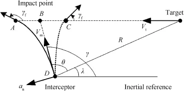
Fig.1.Planar engagement geometry.

Apparently,for θ=90°,the maximum of β=1/sinλ (λ≠nπ,n=0,±1,±2,…).Therefore,it should be ensured that β∈(1,1/sinλ)(λ≠nπ,n=0,±1,±2,…)during the acting interception for any guidance in this engagement geometry.
Lemma 2:when an interceptor is guided by PNS guidance law,the navigation ratio N can uses a negative value or a positive value,but should satisfy Eq.(5).

Substituting Eq.(2)and Eq.(3)into Eq.(6),we have

In order for˙λ to approximate the zero line,˙λ and¨λ must have different signs.Thus,

Since the defnition ˙R≅-Vc,Vc>0(Vcis the closing velocity of interceptor).The navigation ratio as Eq.(5)is obtained From Eq.(8).
Remark:In the classical PN guidance law,the navigation ratio N is a positive value,and should satisfy Eq.(5a).The interception path is shown in Fig.1(path DC).If the navigation ratio N is a negative value,it should satisfy Eq.(5b). The interception path is shown in Fig.1(path DA).
3.Interceptor lateral acceleration
The classical PN lateral commanded acceleration is defned as[10]

where N is a constant,and represents navigation ratio.
The effective navigation ratio can be obtained by Eq.(10) proposed in Ref.[8]

Where N′is effective navigation ratio,N′>2.
If N′is set as a constant,from Eq.(10),N should be a timevarying navigation ratio,and can be derived from Eq.(10),

In the above derivation,we adopt the equation system consisted of Eq.(9)and Eq.(11),which constitutes the CPN guidance in plane.
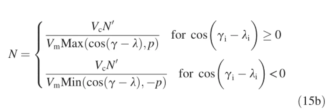
The advantage of time-varying navigation ratio is that,in Eq.(11),N′>2,Vc>0,Vm>0,the sign of navigation ratiocan be determined by cos(γ - λ).Note that,for cos(γ-λ)≥0,N>0,the guidance law is called CPN+,and the interception path is shown in Fig.1(path DC).For cos(γ-λ)<0,the guidance law is called CPN-,and the interception path is shown in Fig.1(path DA).Hence,when CPN is implemented in terminal guidance,it can be determined as CPN+or CPN-by the relation of path angle and LOS angle.CPN+with positive N can be used to intercept the low-speed targets,and CPN-with negative N is used to intercept the high-speed targets.Also,CPN can be used to intercept the stationary targets.Moreover,the capture region of CPN without considering the impact angular constraint is larger than that of PN or RPN with regard to the capture region defned in Ref.[7].
Note that,for cos(γm-λ)→0,N→±∞,an→±∞.The next section will discuss how to avoid this condition.
3.1.Threshold value of time-varying navigation ratio
In order to avoid the condition:cos(γ-λ)→0,N→±∞, an→±∞,a threshold value p of cos(γ-λ)should be set.
Thus,we try to use the required overload to determine the threshold value p.From Eq.(9),the required overload aiis defned as

where˙λiis the initial LOS rate;Vc,iis the initial closing velocity of interceptor;and λiis the initial LOS angle.
For varied threshold value p,the initial acceleration changing from 0 to π with initial path angle is depicted in Fig.2(initial conditions and constants are shown in Section 4).
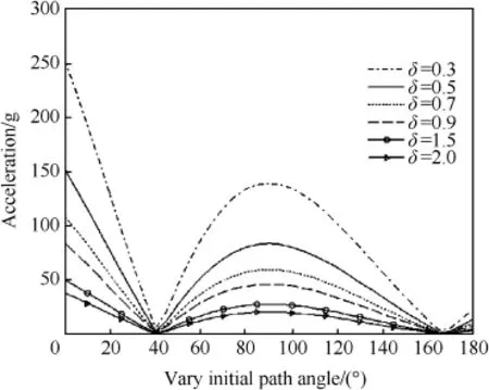
Fig.2.Initial acceleration variations.
From Fig.2,it can be seen that the acceleration at initial time is larger when the initial path angle is near 0°and 90°, and the acceleration decreases as the threshold value p increases.Hence,the threshold value p is determined by the required overload and the initial path angle.Note that,a)for the initial path angle being near 0°or 90°,the required overload at initial time is the largest during fight time;b)in order to intercept high speed target in this engagement geometry (Fig.1),the initial path angle should not be near 0°,which could cause larger required overload.For instance,if the required overload is equal to 50 g,the threshold value p should be set between 0.4 and 0.7.It needs to be explained that the threshold value p can be larger than 1 if the required overload is smaller.
3.2.Defnition of time-varying navigation ratio
Two boundary cases must be considered for computing the navigation ratio N,as shown in Fig.3.
Case I:γi-λi<90°
For γi-λi<90°,the value of γ-λ tends to a value,which is near γi-λiand less than 90°.Thus,the value of N should be defned as

Case II:γi-λi≥90°
For γi-λi≥90°,the value of γ-λ tends to a value, which is near γi-λiand larger than 90°.Thus,the value of N should be defned as

Therefore,the interceptor lateral acceleration can be derived as

where
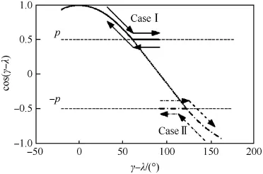
Fig.3.Two boundary cases of navigation ratio.
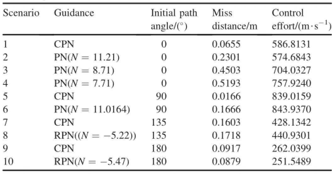
Table 1Scenario parameters.
Note that,for cos(γi-λi)≥0,the guidance law is called CPN+,and the interception path is shown in Fig.1(path DC). For cos(γi-λi)<0,the guidance law is called CPN-,and the interception path is shown in Fig.1(path DA).
4.Simulation results
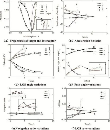
Fig.4.Simulation results for CPN,PN and RPN.
Simulations are run in a MATLAB environment where they are terminated for Vc<0.The range value Rfat this fnalinstant is taken as the miss distance.The target speed Vtis 1500 m/s with(Xt,Yt)=(10,000 m,10,000 m).The interceptor speed Vmis 600 m/s,and the initial range Riis 10,000 m.The interceptor initial position can be calculated through Riand initial LOS angle λi.The seeker model is of a perfect seeker (without noise)with a suffciently large feld of view,but it is assumed to be unable to track the target and the guidance command maintains its last value when the range is below 30 m[11].The simulations are carried out in a planar engagement scenario.
4.1.Simulation with varied initial angles
Because CPN+and CPN-are similar with PN and RPN for intercepting high speed target,we consider the guidance scheme,RPN and PN proposed in Ref.[3]to demonstrate the basic properties of the proposed guidance law.The initial LOS angle λiis 10°,the effective navigation ratio N'is 3,the acceleration saturation asis 30.61 g,and the threshold value p=0.7.Because the navigation ratio is time-varying,we set the mean navigation ratio of CPN as the navigation ratio of PN and RPN for comparison.
The frst two columns in Table 1 indicate the number of scenarios and the guidance schemes used,respectively.The next three columns present the performance variables consisted of the initial path angle,the miss distance and the total control effort.Fig.4 shows the simulation results,where the number of scenarios is indicated in the legend or on each curve.
It can be known from Table 1 and Fig.4 that:
1)Scenarios 2,3,4,6,8and 10 are included for comparison. Scenarios 2,3,4 and 6are presented for comparison with Scenarios 1 and 5.Scenarios 8 and 10 are presented for comparison with Scenarios 7 and 9.Table 1 and Fig.4 indicate that PN and RPN are similar with CPN+and CPN-in performance,respectively.Miss distance of CPN is less than those of PN or RPN,but its control effort is greater than them.It is because that the navigation value of guidance laws cannot be the same.For PN and RPN,the navigation value is fxed.For CPN,the navigation value is time-varying.
2)In Fig.4(e),the navigation ratio N tends to be a fxed value Nfx,which should satisfy Lemma 2.Also note that a certain phase of the curve is an approximate straight-line,where cos(γ-λ)=p or cos(γ-λ)=-p(note from Eq.(15).
3)CPN can adjust the value of navigation ratio according to initial path angle in order to ft head-on engagement or tail-chase engagement.It can be noted from Scenarios 2, 6,8 and 10 that,for the effective navigation ratio N'=3, the absolute value of mean navigation ratio of CPN+is larger than that of CPN-.This is just the advantage of CPN.It is because that,in order for˙λ to approximate the zero line,the required navigation ratio is larger than that of engagement incos(γi-λi)<0,which can be observed from Scenarios 2,3 and 4 in Fig.4(b)and(f)as PN-based guidance laws engage in cos(γi-λi)≥0.When thenavigation ratio decreases from 11.21 to 7.71,˙λ cannot tend to 0,and the lateral acceleration increases abruptly during the fnal phase.This brings about performance degradation manifesting its increased miss distance and control effort(note from scenario 2,3 and 4 of Table 1).
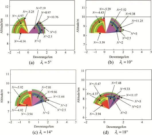
Fig.5.Capture regions for CPN,PN and RPN.
4.2.Capture region for CPN
Fig.5 shows the comparison of the guidance laws(CPN, PN and RPN)for varied values of N by determining all those initial interceptor fight directions and impact angles for which capture is possible.Capture region[12,13]is defned as all those initial interceptor fight directions for which capture is possible.For comparison,PN and RPN capture regions are also shown in Fig.5.
Four cases,with different positions of the interceptor defned through initial LOS angles λitaken as 5°,10°,14°and 18°,are shown.The simulations are performed for 36 varied desired impact angles from 0°to 180°and for 36 different initial path angles from 0°to 180°.Miss distance Rfis less than 0.5 m,the acceleration saturationasis 15.31 g,and threshold value p is 2.0.The mean navigation ratio of CPN is set as the navigation ratio of PN or RPN for comparison also.The green region with same radius represents CPN result with same effective navigation ratio N′.Other color region represents PN results on the left side,and RPN results on the right side.
From Fig.5,the following observations can be made.
1)Capture region of CPN is larger than that of PN or RPN.
2)Capture region shrinks as the value of N decreases,and frst ascends and then descends as the value of λiincreases from 5°to 18°.
Finally,when the CPN guidance law is implemented in a practical system,the requirements for a seeker-based homing interceptorwouldbeaseekerwithaverylargefeldofview,and the seeker axis can be directed along the relative LOS with respecttothemissilebodyaxis[3].Iftheinterceptorisusedina command guided mode,then this requirement may be avoided.
5.Conclusions
In this paper,a new guidance law called the CPN guidance law is developed for interception of high-speed targets,which is a common case for ballistic targets.The guidance law provides the valuable features.Firstly,CPN can incorporate the useful features of both PN and RPN,and determine headon engagement(PN)or tail-chase engagement(RPN)through initial path angle.Secondly,CPN use a time-varying navigation ratio and can adjust the value of navigation ratio according to initial path angle in order to ft head-on engagement or tail-chase engagement.Therefore,the capture region of CPN is larger than those of other guidance laws using PN-based methods.Simulation results are shown to support these claims.
[1]Tal S,Golan OM.Head pursuit guidance.J Guid Control Dyn 2007;30:1437-44.
[2]Lin YP,Lin CL,Li YH.Development of 3-D modifed proportional navigation guidance law against high-speed targets.IEEE Trans Aerosp Electron Syst 2013;49:677-87.
[3]Prasanna HM,Ghose D.Retro-proportional-navigation:a new guidance law for interception of high-speed targets.J Guid Control,Dyn 2012;35:377-86.
[4]Erer KS,Merttopcuoglu O.Indirect impact-angle-control against stationary targets using biased pure proportional navigation.J Guid Control Dyn 2012;35:700-3.
[5]Ratnoo A,Ghose D.Impact angle constrained interception of stationary targets.J Guid Control Dyn 2008;31:1816-21.
[6]Ratnoo A,Ghose D.Impact angle constrained guidance against nonstationary nonmaneuvering targets.J Guid Control Dyn 2010;33:269-75.
[7]Ratnoo A,Ghosey D.Satisfying terminal angular constraint using proportional navigation.In:AIAA Guidance,Navigation,and Control Conference and Exhibit,August 10,2009-August 13,2009.Chicago,IL, United states:American Institute of Aeronautics and Astronautics Inc.; 2009.
[8]Ravindra Babu K,Sarma IG,Swamy KN.Switched bias proportional navigation for homing guidance against highly maneuvering targets.J Guid Control Dyn 1994;17:1357-63.
[9]Zarchan P.Tactical and strategic missile guidance.6th ed.15.American Institute of Aeronautics and Astronautics;2002.p.11-28.
[10]Siouris GM.Missile guidance and control systems.Springer;2004. p.113-95.
[11]Byung Soo K,Jang Gyu L,Hyung Seok H.Biased PNG law for impact with angular constraint. IEEE Trans Aerosp Electron Syst 1998;34:277-88.
[12]Ghawghawe SN,Ghose D.Pure proportional navigation against timevarying targetmaneuvers.IEEE Trans Aerosp Electron Syst 1996;32:1336-47.
[13]Yan L,Zhao JG,Shen HR,Li Y.Biased retro-proportional navigation law for interception of high-speed targets with angular constraint.Def Technol 2014;10:60-5.
Received 9 December 2013;revised 29 January 2014;accepted 20 March 2014 Available online 31 July 2014
*Corresponding author.
E-mail address:haofangshi@163.com(J.G.ZHAO).
Peer review under responsibility of China Ordnance Society.
http://dx.doi.org/10.1016/j.dt.2014.07.004 2214-9147/Copyright©2014,China Ordnance Society.Production and hosting by Elsevier B.V.All rights reserved.
Copyright©2014,China Ordnance Society.Production and hosting by Elsevier B.V.All rights reserved.
- Defence Technology的其它文章
- Optimization of process parameters of the activated tungsten inert gas welding for aspect ratio of UNS S32205 duplex stainless steel welds
- Investigation on the foaming behaviors of NC-based gun propellants
- Indirect robust control of agile missile via Theta-D technique
- Numerical simulation of base fow with hot base bleed for two jet models
- Analysis on the resistive force in penetration of a rigid projectile
- Numerical simulation of detonation of an explosive atmosphere of liquefed petroleum gas in a confned space

