Analysis on the resistive force in penetration of a rigid projectile
Xiao-wei CHEN*,Ji-cheng LI
Institute of Systems Engineering,China Academy of Engineering Physics,Mianyang 919416,China
Analysis on the resistive force in penetration of a rigid projectile
Xiao-wei CHEN*,Ji-cheng LI
Institute of Systems Engineering,China Academy of Engineering Physics,Mianyang 919416,China
According to the dimensionless formulae of DOP(depth of penetration)of a rigid projectile into different targets,the resistive force which a target exerts on the projectile during the penetration of rigid projectile is theoretically analyzed.In particular,the threshold Vcof impact velocity applicable for the assumption of constant resistive force is formulated through impulse analysis.The various values of Vccorresponding to different pairs of projectile-target are calculated,and the consistency of the relative test data and numerical results is observed.
Rigid projectile;Constant resistive force;Impact velocity
1.Introduction
The penetration of a rigid projectile into thick target (metals,concrete,etc.)has been an intense research topic for many decades.The analysis of resistive force which a target exerts on the projectile during penetration is the basis of all relative problems.Usually the resistive force is obtained from the dynamic cavity expansion model.
The resistive force obtained from the dynamic cavity expansion model is usually expressed as the following form[1].

where d is the diameter of projectile shank;σyand ρ are yield stress and density of target material,respectively;A and B are dimensionless material constants[2-5];V is the rigid-body velocity of projectile during penetration;N1and N2are the dimensionless parameters related to the nose shape of projectile and the friction coeffcient μ[1].In general,if the nose shape can be represented by the nose shape function y=y(x)for an arbitrary nose shape,then the nose factors are defned as
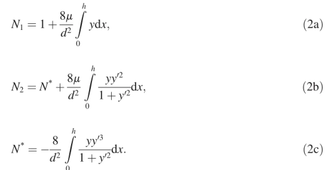
where h is the height of nose;and N*in Eq.(2c)is defned as the geometry factor of projectile.Regarding the ogival and conical noses,the formulae of N1,N2and N*are very simple [1].Obviously,the resistive force consists of two parts:quasistatic resistive force(target strength term)AN1σyand dynamic resistive force(inertial term)BN2ρV2.

Fig.1.Dependence of(X/d)/I on I/N based on Eq.(3).
There have been many arguments about the contributions of the target strength term and the inertial term to the resistive force.For example,Batra and Wright[6]numerically analyzed the resistive force of an infnitely long,sphericallynosed rigid projectile penetrating into a rigid plastic target in a series of simulations,and found that the dimensionless constant B in Eq.(1)is just 0.0733,which is much smaller than that used in general analysis.Thus,they concluded that the dependence of the target resistive force on the impact velocity is much less than that obtained from the dynamic cavity expansion model.Forrestal et al.and Frew et al.conducted a series of penetration tests of concrete targets to measure the acceleration curves[7,8]and found that the effect of the inertial term is very small in the range of the impact velocity(<460 m/s).Forrestal and Warren's analysis on the penetration of ogive-nosed projectile into aluminum target also suggested that the resistive force is dominated by the target strength term when the impact velocity is below a certain value[9].Recently,Rosenberg and Dekel conducted lots of simulations[10]and declared that,for different pairs of projectiles with various nose shapes(ogive,spherical,conical and fat)and target(aluminum and steel),the resistive force is constant and independent on the impact velocity in a certain range of impact velocities(<1.5 km/s).However,if the impact velocity exceeds a certain threshold value,the dynamic cavity expansion model,which includes both the target strength term and inertial term,is appropriate.Further more,the threshold ofimpact velocity depends on the nose shape of projectile and target material.
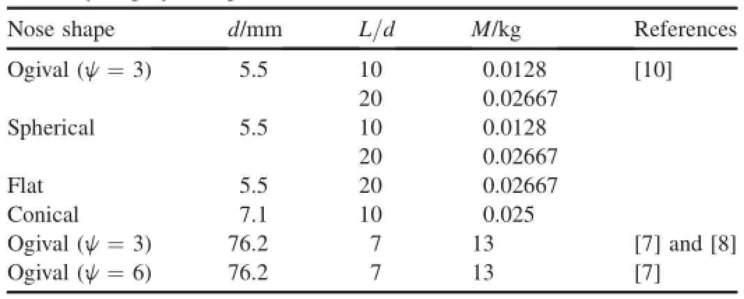
Table 1Summary of projectile parameters.

Table 2A summary of material parameters of different targets.
Chen and Li defned two dimensionless parameters[1],i.e. impact function I and geometry function of projectileN,and then analyzed the parameters which dominate the penetration dynamics of a rigid projectile in detail.In fact,based on the relative discussions about I and N,the respective effects of the target strength term and the inertial term in the dynamic cavity expansion model can be analyzed,too.Based on the previous preparatory work in Ref.[11],the present paper further analyzed the penetration of rigid projectile,and obtained some conclusions which have good agreement with the test data in Refs.[7,8]and the simulation results in Ref.[10].
2.Formulae of DOP
Based on Eqs.(1,2),Chen and Li[1],Li and Chen[5] indicated that the dimensionless DOPs of different target materials subjected to rigid projectile impact are only dominated by two dimensionless factors,i.e.impact function I and geometry function of projectile N,and the dimensionless formula of DOP subjected to the impact of rigid projectiles with various nose shapes is
where X is DOP,and the respective expressions of I and N are

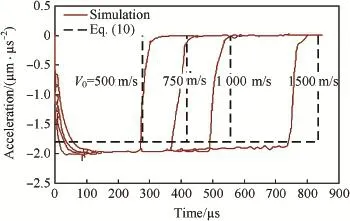
Fig.2.Simulations and model predictions of decelerations vs time for projectile with L/d=20 and ψ=3 penetrating aluminum target with σy=400 MPa at different impact velocities.
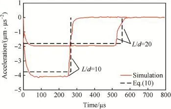
Fig.3.Simulations and model predictions of decelerations vs time for projectiles with ψ=3 and different values of L/d penetrating aluminum target with σy=400 MPa at 1000 m/s.

where M is the mass of projectile;V0is the initial impact velocity;I*is the dimensionless impact factor;and λ is the dimensionless mass ratio.
Deep penetration usually relates to a sharp and slender projectile.The geometry function of projectile N,is large, usually N>100 and I<N.Thus,Taylor series expression of Eq.(3)gives

Fig.1 shows the dependence of(X/d)/I on I/N based on Eq.(3).Chen and Li[1]further declared that X/d is much more sensitive to the impact function I than the geometry function of projectile N when the value of N is large enough (which usually corresponds to a sharp and slender projectile, e.g.earth penetrating projectile).If I<<N,the upper limit of Eq.(6)can be obtained.

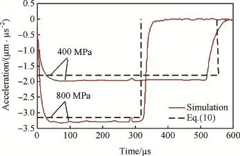
Fig.4.Simulations and model predictions of decelerations vs time for projectile with L/d=20 and ψ=3 penetrating aluminum targets with σy=400 MPa or 800 MPa at 1000 m/s.
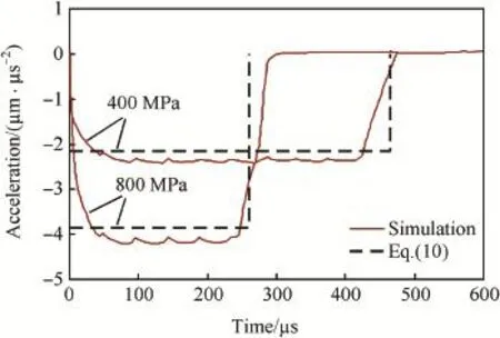
Fig.5.Simulations and model predictions of decelerations vs time for projectile with L/d=20 and ψ=3 penetrating steel targets with σy=400 MPa or 800 MPa at 1000 m/s.
Regarding a concrete target,the depth of the front crater, k/2,should be included in Eqs.(3,6 and 7),[5].
On the other hand,by integrating a large amount of test data,Chen and Li[1]suggested empirically that,in a wide range of I/N,the dimensionless DOP X/d has a simple linear relationship with the impact function I

More discussion on Eq.(8)can be found in Ref.[1].
We may further discuss the effect of the higher order terms in Eq.(6).Regarding the deep penetration,we usually have 100 < N < 200 and I≈ 50 [12],thuswehave 0.125<I/2N<0.25.Therefore,we may think that Eq.(8)is equal to the value that is Eq.(7)minus the higher order terms in Eq.(6).
3.Analysis on resistive force
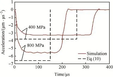
Fig.6.Simulations and model predictions of decelerations vs time for conicalnosed projectile penetrating aluminum targets with σy=400 MPa or 800 MPa at 1000 m/s.
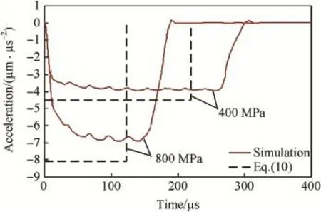
Fig.7.Simulations and model predictions of decelerations vs time for conicalnosed projectile penetrating steel targets with σy=400 MPa or 800 MPa at 1000 m/s.
From the defnitions in Eqs.(4)and(5),it is easy to know that Eqs.(7)and(8)are the expressions of displacement under a constant force.The total penetration time is te=V0/a, where a is the constant deceleration.Based on the formula of displacement,i.e.X=V0te-at2e/2=V20/(2a),X can be substituted with the expressions in Eqs.(7,8)to obtain the corresponding deceleration.

Thus,the corresponding resistive force just equals to the target strength term in Eq.(1)or is multiplied by a constant value 4/π.Basically,according to the analysis in the last paragraph of Section 2,the difference between Eqs.(9)and (10)is caused by the effect of the higher order terms in Eq.(6).
For concrete target,the crater region and the tunnel region need to be considered,respectively.Forrestal et al.[13]suggested the expressions of the resistive forces in crater and tunnel,respectively,

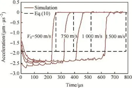
Fig.8.Simulations and model predictions of decelerations vs time for spherical-nosed projectile with L/d=20 penetrating aluminum target with σy=400 MPa at different impact velocities.
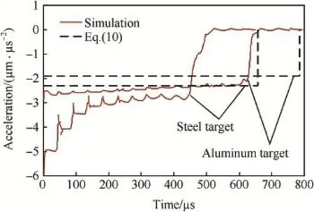
Fig.9.Simulations and model predictions of decelerations vs time for spherical-nosed projectile with L/d=20 penetrating aluminum and steel targets with σy=400 MPa at 1500 m/s.

Comparatively,Rosenberg and Dekel[10]neglected the inertial term and gave the formulae of DOP and the deceleration of projectile during penetration
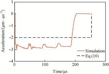
Fig.10.Simulations and model predictions of decelerations vs time for fatnosed projectile penetrating steel target with σy=400 MPa at 500 m/s.
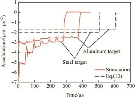
Fig.11.Simulations and model predictions of decelerations vs time for fatnosed projectile penetrating aluminum and steel targets with σy=400 MPa at 1000 m/s.

They also defned the effective length of projectile Leff=4M/(ρpπd2).
Obviously,the nose shape factor of projectile,N1,is taken into account in Eqs.(9)and(11c)compared to Eq.(12),and thus Eqs.(9)and(11c)have a more comprehensive applicability.Besides,Eq.(9)only relates to the case of I<<N,i.e. the impact velocity is lower,while Eqs.(10)and(11c)are appropriate for a wider range of I/N.Therein,the following analyses are mainly to use Eqs.(10)and(11c)to discuss the resistive force.
The simulations on penetration of rigid projectiles with various nose shapes,such as ogival,spherical,conical and fat, into the aluminum and steel targets gave the corresponding deceleration data[10].In the tests[7,8],the deceleration of projectile a during penetration was recorded by a singlechannel acceleration data recorder.According to the relative parameters of projectiles and targets,the corresponding decelerations a can be calculated from Eqs.(10)and(11c), and the stopping time of penetration,te,can be obtained by V0/a.Thus,the rationalities and explicabilities of Eqs.(10) and(11c)can be verifed compared with the test data and the simulation results.
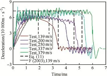
Fig.12.Test data and model predictions of decelerations vs time for projectile with ψ=3 penetrating concrete target with σcf=23 MPa at different impact velocities.
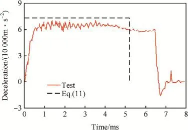
Fig.13.Test data and model predictions of decelerations vs time for projectile with ψ=6 penetrating concrete target with σcf=23 MPa at 379 m/s.
The parameters of projectiles and target materials in the calculations are listed in Table 1 and Table 2,respectively. In the calculations related to Eq.(10),according to Ref.[1], the friction coeffcient μ take values of 0.02 for ogival nose and μ=0.1 for spherical and conical noses,respectively,then the corresponding dimensionless parameter of projectile,N1,can be obtained.In the calculations related to Eq.(11c),according to Ref.[7],the resistive force R=165 MPa for projectiles with φ=76.2 mm and ψ=3 or 6 penetrating into the concrete target with σcf=23 MPa. Comparatively,R = 360 MPa for projectile with φ=76.2 mm and ψ=3 penetrating into the concrete target with σcf=39 MPa,and R=265 MPa for projectile with φ=76.2 mm and ψ=6 penetrating into the concrete target with σcf=39 MPa.

Fig.14.Test data and model predictions of decelerations vs time for projectile with ψ=3 penetrating concrete target with σcf=39 MPa at different impact velocities.

Fig.15.Test data and model predictions of decelerations vs.time for projectile with ψ=6 penetrating concrete target with σcf=39 MPa at different impact velocities.
Figs.2-11 show the simulations of deceleration versus time[10]and model predictions from Eq.(10);Figs.12-15 show the test data of deceleration versus time[7]and model predictions from Eq.(11c);Fig.16 shows the test data of deceleration versus time[8]and model predictions from Eq. (11c).Specially,the theoretical prediction in Ref.[7]corresponding to the cases of low velocity impact are also given in Figs.12-16 and labeled as F(2003),and this prediction is less than that from Eq.(11c).Moreover,the crater region is neglected in the analysis.
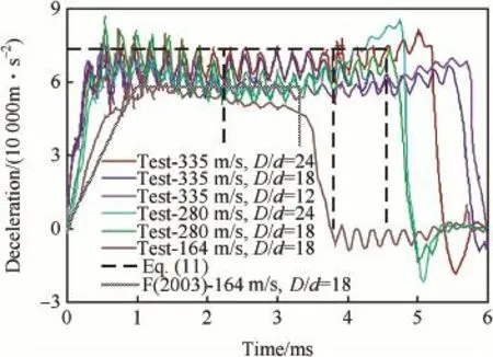
Fig.16.Test data and model predictions of decelerations vs.time for projectile with ψ=3 penetrating concrete targets with σcf=23 MPa and different values of D/d at different impact velocities.

Table 3The ranges of impact velocity threshold Vc/(km·s-1)[10].
Regarding that penetration of ogive-nosed projectile into aluminum and steel targets(Figs.2-5),in the range of impact velocity(V0≤1000m/s)in the simulations,the theoretical decelerations a from Eq.(10)have good agreement with the corresponding simulation results.Penetration of conical-nosed projectile(Figs.6,7)is similar to that of ogive-nosed projectile,and the numerical decelerations a are still constant for V0=1000 m/s but a little less than the modeling prediction. For spherical-nosed projectile(Figs.8,9),the numerical decelerations a also keep as a constant value for V0≤1000 m/s, and are larger than the modeling prediction.However,for V0=1500 m/s,the numerical deceleration a is no longer a constant,specially for steel targets,the effect of inertia term is almost same as that of target strength term at V0=1500 m/s (Fig.9).Penetration of fat-nosed projectile(Figs.10,11)is similar to that of spherical-nosed projectile.Thus,we can see that,for the penetration of rigid projectiles into aluminum and steel targets,when V0is under a certain value,the relative deceleration a can assuredly be approximated as a constant and simply expressed by Eq.(10).However,when V0exceeds a certain threshold of impact velocity Vc,the inertial term of resistive force becomes obvious and the assumption of constant deceleration no longer exists.Also,the different pairs of projectile-target corresponds to different values of Vc,i.e.,Vcis related to the projectile geometry and target material.
From Figs.12-16,it can be seen that almost all the decelerations a are kept as an approximate constant,i.e.,the effect of the inertia term could be ignored.Specially,when the impact velocity is comparatively low(V0<200 m/s),the test data are more close to the corresponding predictions in Ref.[7].However,when the impact velocity increases (V0>200 m/s),the prediction of Eq.(11c)shows a better agreement with the test data.Moreover,the cratering time is far less than the subsequent penetration time,thus the history of the crater region could be neglected.As that mentioned before,the prediction in Ref.[7]is less than that from Eq.(11) with a factor of 4/π.The essential is that,for the linear dependence of dimensionless DOP X/d on the impact function I,is Eq.(7)or Eq.(8)more reasonable?It is shown from the above analysis that Eq.(7)is appropriate to the case of lower velocity impact and Eq.(8)is applicable for a wider range of impact velocity.
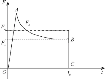
Fig.17.The resistive force versus time.
4.Analysis on thresholds of impact velocity Vc
As mentioned in Section 3,Rosenberg and Dekel[10] conducted the numerical simulations on the penetrations of rigid projectiles with different nose shapes into aluminum and steel targets,respectively,and found that the hypothesis of constant resistive force comes into existence when the impact velocity V0locates in a certain range;however,when impact velocity increases to a threshold value Vc,the inertial term of the resistive force must be taken into account.Based on their simulations,Rosenberg and Dekel[10]also obtained the ranges of Vccorresponding to different pairs of projectiles and targets,as listed in Table 3.Meanwhile,they also analyzed the test data of concrete penetration[14]and found that the deceleration a is almost a constant in the impact velocity range of 400<V0<1200 m/s.
We note that the variation of resistive force F in Eq.(1) with time t is an approximate parabola,as demonstrated qualitatively in Fig.17,and it can be validated by the dynamic cavity expansion model.In Fig.17,the broken line represents the target strength term Fs=πAσyN1d2/4 in Eq.(1)and corresponds to the deceleration predicted by Eq.(9).The difference between the solid curve AB and the broken line is the inertial termFd=πd2BρV2N2/4,and the dash-dotted line represents the constant resistive force Fc=AσyN1d2and corresponds to the deceleration predicted by Eq.(10).It should be noted that Fcis 4/π times of Fs.
From Fig.17 it can be known that,when the impact velocity V0is comparatively low,the impulse of F(i.e.,the area surrounded by the solid curve OABC)approximates to the impulse of Fc(i.e.,the area under the dash-dotted line),and thus F could be simplifed approximately as the constant resistive force Fc.However,when V0reaches a higher value, the impulse of F must be greater than that of Fc.According to the impulse equivalence,the impact velocity threshold Vcexists only when the impulse of F is less than or equal to that of Fc.By ignoring the initial phase of penetration,this qualifcation could be expressed as As the curve of F(solid curveAB)is comparatively mild,it assumes that the deceleration is constant,and the rigid-body velocity of projectile during penetration process is


and the total penetration time is

From Eq.(13),an in equation can be obtained.


Eq.(17)gives a parameter range of rigid projectile penetration under the assumption of constant resistive force.Corresponding to Fig.1,Eq.(8)can be employed to predict DOP in the range of 0<I/N≤0.82;while out of this range,the approximation of constant resistive force is no longer appropriate,i.e.the effect of the inertial term in dynamic cavity expansion model is distinct,and Eq.(3)should be employed to predict DOP.The present formulation further declares the applicable range of the empirical formula of DOP in Ref.[1] (Eq.(8)).
Eq.(17)gives a threshold of impact velocity.

In other words,for a rigid projectile penetration under V0≤Vc,it needs not to simultaneously consider the target strength term and the inertial term,instead,only the modifed constant resistive force Fc=d2AσyN1or Fc=d2R is used. Obviously,the threshold of impact velocity Vcdepends on the nose shape of projectile,target material and its strength,which is the same as the numerical results in Ref.[10].Regarding the different pairs of projectiles and targets,the thresholds of impact velocity Vccan be easily obtained from Eq.(18).
Therein,Vcfor different pairs of projectile-target is discussed with Forrestal's test data,in which the projectiles include ogival(ψ=2,3,4.25,6),spherical and conical nose shapes,and the targets include elastic,perfectly plastic metals, strain-hardening metals,concrete and soil,etc.Flat-nosed projectile is also taken into account in our analysis in order to compare with the results in Ref.[10].6061-T651 aluminum and steel with strength of 400 MPa[2],as shown in Table 2, and concrete with σcf=58.4 MPa in Ref.[14]are selected as the analytical target materials.Moreover,for concrete target with σcf=58.4 MPa,its density is simply defned as ρ=2320kg/m3,A=9.422 and B=1 according to Li and Chen[5].Table 4 shows the different impact velocity thresholds of different pairs of projectile-target.
It can be concluded that the predictions of impact velocity thresholds of different pairs of projectile-target in Table 4 are close to the numerical results in Table 3,which obtained byRosenberg and Dekel[10].In particular,the predictions of ogival(ψ=3),spherical,and fat noses are a little less than the corresponding ranges in Table 3,while the predictions of conical nose are a little larger than those in Table 3.The deviations between Tables 3 and 4 are trusted to come from the implication of theoretical model and numerical simulation,but they all locate in the allowed range of 10%.Moreover,the prediction of the effect of nose shape on Vcis completely consistent with the results in Ref.[10].
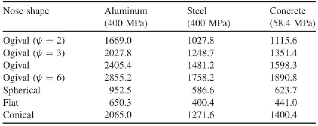
Table 4Theoretical predictions of Vc(in m/s)of different pairs of projectile-target.
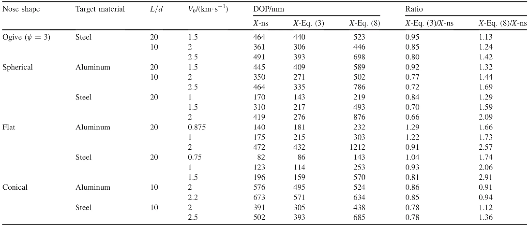
Table 5Comparison of DOPs from theoretical formulae and simulations in the case of V0>Vc
With re-check of Figs.2-11,since the impact velocities of most cases are less than the impact velocity threshold Vc,the assumption of constant resistive force is available.Exceptionally,regarding the cases of spherical and fat nose projectiles impacting aluminum and steel targets at V0=1500 m/ s and V0=1000 m/s,respectively,as the impact velocities exceed the threshold(see Figs.8,9 and 11),the effect of the initial term is quite dominating during the penetration.Similarly,as V0<Vcin the concrete penetrations[7,8],almost all the decelerations a are kept as constant,as shown in Figs. 12-16.
Thus,the rationality of above theoretical analysis and Eq. (18)are further validated,and the applicability of the predictions of Vcon the other cases of Table 4 can also be confrmed.
According to above analysis,in the range of V0≤Vc,Eq. (8)is reasonable for predicting DOP;and for V0>Vc,DOP should be calculated using Eq.(3).Due to the limit of experimental conditions,no test data of V0>Vchas been reported in published literatures regarding to the pairs of projectile-target in Table 4,and thus it is impossible to check the applicable range of Eqs.(3)and(8)by experimental results.However,Rosenberg and Dekel[10]also conducted some simulations under the condition of V0>Vc.Their simulations use two kinds of aspect ratios of projectile,i.e. L/d=20,10.Target materials are aluminum and steel with strength of 400 MPa,which are listed in Table 2.The DOPs predicted by theoretical analysis are further compared with the simulation results to check the applications of Eqs.(3)and(8). The comparative results are listed in Table 5,where the labels of X-ns,X-Eqs.(3)and(8).represent DOPs predicted by simulation,Eqs.(3)and(8),respectively.
It can be found from Table 5 that,for any kind of nose shape,the most values of ratio X-Eq.(3)/X-ns are close to 1, and the relative deviations mostly locate in the allowed range of 20%.In contrast,the most values of ratio X-Eq.(8)/X-ns are larger than 1 and the relative deviations are out of the allowed range of 20%.It indicates that Eq.(8)is indeed inappropriate and only Eq.(3)can be used to predict DOP accurately in the case of V0>Vc.
5.Conclusions
According to the dimensionless formulae of DOP of different targets penetrated by a rigid projectile,this paper theoretically analyzed the resistive force exerting on the projectile during the penetration.According to the impulse equivalence,the impact velocity threshold Vcwas formulated, which is applicable for the assumption of constant resistive force.Vconly depends on the nose shape of projectile and target material.The applicable ranges of various formulae of DOP were also checked up based on the test data in Refs.[7,8] and the simulation results in Ref.[10].Especially,for V0>Vc, Eq.(8)formulated from the assumption of constant resistive force is no longer appropriate and only Eq.(3)is able to be employed to predict DOP.
The values of Vcfor different pairs of projectile-target in the present theoretical analysis are consistent with the simulation results in Ref.[10].The relative test data also confrmed that the values of Vcare correct and applicable.In particular, the impact velocity threshold Vcare formulated out withcombined the effects of projectile geometry and target material.
Acknowledgments
This work is supported by the National Outstanding Young Scientist Foundation of China(11225213),and Major Program of National Natural Science Foundation of China(Grant No. 11390362).
[1]Chen XW,Li QM.Deep penetration of a non-deformable projectile with different geometrical characteristics. Int J Impact Eng 2002;27(6):619-37.
[2]Forrestal MJ,Luk VK.Dynamic spherical cavity-expansion in a compressible elastic-plastic solid.Trans ASME J ApplMech 1988;55(3):275-9.
[3]Forrestal MJ,Luk VK.Penetration into soil targets.Int J Impact Eng 1992;12(5):427-44.
[4]Luk VK,Forrestal MJ,Amos DE.Dynamics spherical cavity expansion of strain-hardening materials. Trans ASME J Appl Mech 1991;58(1):1-6.
[5]Li QM,Chen XW.Dimensionless formulae for penetration depth of concrete target impacted by a non-deformable projectile.Int J Impact Eng 2003;28(1):93-116.
[6]Batra,Wright TW.Steady state penetration of rigid perfectly plastic targets.Int J Eng Sci 1986;24(1):41-54.
[7]Forrestal MJ,Frew DJ,Hickerson JP,Rohwer TA.Penetration of concrete targets with deceleration-time measurements.Int J Impact Eng 2003;28(5):479-97.
[8]Frew DJ,Forrestal MJ,Cargile JD.The effect of concrete target diameter on projectile deceleration and penetration depth.Int J Impact Eng 2006;32(6):584-94.
[9]Forrestal Michael J,Warren Thomas L.Penetration equations for ogivenose rods into aluminum targets.Int J Impact Eng 2008;35(8):727-30.
[10]Rosenberg Z.Dekel E.The penetration of rigid long rods-revisited.Int J Impact Eng 2009;36(4):551-64.
[11]Xiaowei Chen,Jicheng Li.Analysis of penetration depth and resistive force in the deep penetration of a rigid projectile.Explos Shock Waves 2009;29(6):584-9[in Chinese].
[12]Chen XW,Li QM,Zhang FJ,He LL.Investigation of the structural failure of penetration projectiles.Int J Prot Struct 2010;1(1):41-65.
[13]Forrestal MJ,Altman BS,Cargile JD,Hanchak SJ.An empirical equation for penetration depth of ogive-nose projectiles into concrete targets. Int J Impact Eng 1994;15(4):395-405.
[14]Frew DJ,Hanchak SJ,Green ML,Forrestal MJ.Penetration of concrete targets with ogive-nose steel rods.Int J Impact Eng 1998;21(5):489-97.
Received 5 December 2013;revised 13 March 2014;accepted 12 June 2014 Available online 22 July 2014
*Corresponding author.Tel.:+86 816 2484336.
E-mail address:chenxiaoweintu@yahoo.com(X.W.CHEN).
Peer review under responsibility of China Ordnance Society.
http://dx.doi.org/10.1016/j.dt.2014.06.007 2214-9147/Copyright©2014,China Ordnance Society.Production and hosting by Elsevier B.V.All rights reserved.
Copyright©2014,China Ordnance Society.Production and hosting by Elsevier B.V.All rights reserved.
- Defence Technology的其它文章
- Optimization of process parameters of the activated tungsten inert gas welding for aspect ratio of UNS S32205 duplex stainless steel welds
- Investigation on the foaming behaviors of NC-based gun propellants
- Indirect robust control of agile missile via Theta-D technique
- Numerical simulation of base fow with hot base bleed for two jet models
- Numerical simulation of detonation of an explosive atmosphere of liquefed petroleum gas in a confned space
- Combined proportional navigation law for interception of high-speed targets

