Indirect robust control of agile missile via Theta-D technique
Di ZHOU*,Quan LI
School of Astronautics,Harbin Institute of Technology,Harbin 15001,China
Indirect robust control of agile missile via Theta-D technique
Di ZHOU*,Quan LI
School of Astronautics,Harbin Institute of Technology,Harbin 15001,China
An agile missile with tail fns and pulse thrusters has continuous and discontinuous control inputs.This brings certain diffculty to the autopilot design and stability analysis.Indirect robust control via Theta-D technique is employed to handle this problem.An acceleration tracking system is formulated based on the nonlinear dynamics of agile missile.Considering the dynamics of actuators,there is an error between actual input and computed input.A robust control problem is formed by treating the error as input uncertainty.The robust control is equivalent to a nonlinear quadratic optimal control of the nominal system with a modifed performance index including uncertainty bound.Theta-D technique is applied to solve the nonlinear optimal control problem to obtain the fnal control law.Numerical results show the effectiveness and robustness of the proposed strategy.
Agile missile;Robust control;Optimal control;Theta-D technique
1.Introduction
To intercept highly maneuverable targets in the endoatmosphere,modern air defense missiles are required to defeat targets by direct body-to-body impact.However,the traditional tail-controlled missile cannot quickly respond to an acceleration command to achieve“hit-to-kill”at an altitude of 20 km above the earth's surface because the dynamic control effectiveness is weak.An approach to improve the agility of a missile is to utilize lateral thrust besides aerodynamic force. As shown in Fig.1,an agile missile is usually equipped with tail fns and pulse thrusters,so it is also called blended controlled missile.Forexample,the PatriotAdvanced Capability-3 missile is equipped with 4 steering fns at its tail and 180 attitude control motors(pulse thrusters)ahead of the center-of-gravity of the missile.
Many control methods have been used to the autopilot design of agile missile[1-12].Some control methods[1-6], such as linear quadratic optimal control,singular perturbation analysis and quantized control allocation,were applied to autopilot designs based on linearized motion models of the missiles.Since the exact dynamics of a missile is nonlinear, the above researches are local and may be unreliable in a wide range of fight conditions.
Some autopilots have been designed for blended controlled missiles based on nonlinear models[7-10].In Ref.[7],the zero dynamics of missile were analyzed,and a feedback linearization approach was employed to design an optimal controller for the missile.In Ref.[8],pitch and yaw motions were decoupled by feedback linearization,and RBF neural network sliding mode control was applied to design a controller.The lateral thrust was treated as a continuous variable[7,8].In Ref.[9],the predictive control was applied to design a lateral thrust control law,and the active disturbance rejection technique wasused in aerodynamic control. Although the pulse-like dynamics of pulse thrusters were considered in the simulation,the stability of the closed-loopsystem was not analyzed.In Ref.[10],the nonlinear model has been analyzed and simplifed,and then the sliding mode control was employed to design a controller for tracking an angle of attack command.The pulse-like property of lateral thrust was discussed only in the implementation of autopilot rather than in the stability analysis.
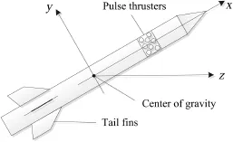
Fig.1.Diagram of missile and coordinate system.
In practice,a pulse thruster works in on-off mode with a fxed period.Therefore,the lateral thrust is a pulse-like variable and can be approximated by a zero-order holder.The aerodynamic force is a continuous variable.The mixed control inputs,continuous and discontinuous control inputs,bring a challenge to the autopilot design and stability analysis of agile missile control system.To handle this problem,two strategies have been proposed.In Ref.[11],a two-step strategy was proposed and the autopilot was designed by state-dependent Riccati equation(SDRE)approach.Based on the nonlinear modelofagilemissile,acontinuousSDRE feedback was translated into a nonlinear quadratic optimal control problem,and the performance index was modifed with uncertainty bound.SDRE approach is applied to solve the problem to obtain a continuous feedback controller.However, to track the acceleration command quickly enough,the fn defections usually reach their upper or lower limits in the simulation.
In this paper,the indirect robust control strategy is integrated with Theta-D technique[13,14]to solve the problem. Theta-D solution to the Hamilton-Jacobi-Bellman(HJB) equation is obtained by adding some small perturbations to the performance index and using the power series expansion to the co-state.A closed-form solution is obtained by taking fnite terms in the series expansion.Design fexibility is brought from the parameters in the additional perturbations, and an appropriate tracking accuracy can be achieved easily. The saturation of fn defections can be avoided by the free split of the state weighted matrix in the performance index.
2.Nonlinear model of agile missile
We consider an axisymmetric skid-to-turn missile in its terminal guidance process.The roll rate and roll angle are both assumed zero.

The nonlinear dynamics of the agile missile[11]in pitch and yaw planes is given in terms of angle of attack α,sideslip angle β,yaw rate ωy,and pitch rate ωzas controller was designed.Accounting for the pulse-like lateral thrust,the nonlinear tolerance of the feedback system was analyzed when the control cannot be implemented ideally. Some suffcient conditions were given to guarantee the asymptotic stability of the closed-loop system.
In Ref.[12],an indirect robust control strategy via SDRE approach was presented for the missile.It was supposed that there exists a continuous feedback controller for the acceleration tracking problem.There were errors between actual inputs from actuators and computed inputs from the controller. A virtual robust control problem was formed by treating the errors as input uncertainties.Then,the robust control problem where δyand δzare the defections of rudder and elevator, respectively;nyand nzare the equivalent ignition numbers of pulse thrusters in the pitch and yaw planes,respectively;m,V, S and L are the mass,velocity,reference area and reference length of the missile,respectively;Jyand Jzare the moments of inertia of the missile;q is the aerodynamic pressure;Cx,cα, cβ,cδy,cδz,mα,mβ,mδy,mδz,mωyand mωzare aerodynamic coeffcients;d is the moment arm of the lateral thrust;T0is the equivalent thrust produced by one thruster.
Eq.(1)can be rewritten as

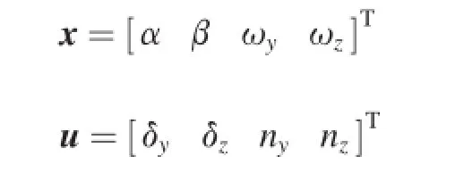
where the states and control inputs are defned as
Eq.(2)can be translated into a linear-like structure with state-dependent coeffcient matrices

where
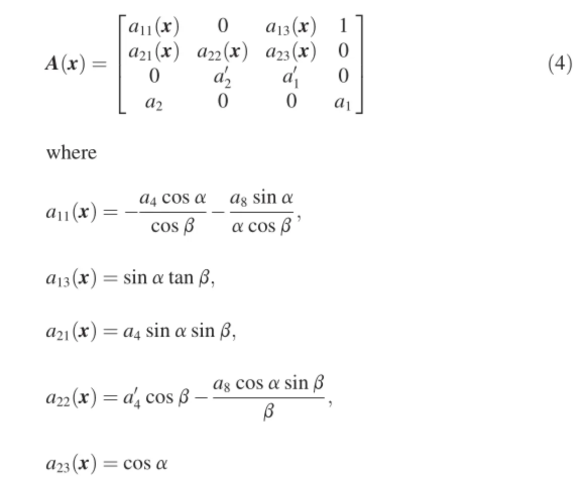
and

where a1,a2,…a8andare dynamic coeffcients. They are defned as
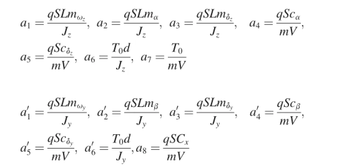
The pitch and yaw accelerations are chosen as the outputs of the system,i.e.,y=[ayaz]T,and the output equation is given by

where

3.Nonlinear tracking system
The acceleration commands are produced by the following reference system:

where z is the reference state;and yris the reference output. Here,we assume that F(z)is continuously differentiable and point-wise stabilizable,and the pair(F(z),H(z))is point-wise observable.
A cost function of tracking performance is given by

where Q and R are constant weighting matrices,and both are positive defnite.
Taking the reference system into account,the performance index Eq.(11)is translated into

where


Corresponding to the performance index Eq.(12),the nonlinear state equation is written as

where
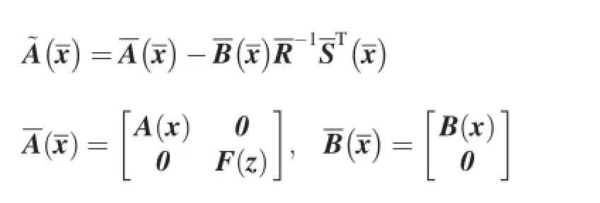

Now,the nonlinear optimal tracking problem described by Eqs.(1)-(11)has been converted into an optimal state regulator problem described by Eq.(12)and Eq.(13).
In practice,all of the computed inputs u,fn defections and ignition numbers of pulse thrusters,are sent to the actuators, and then the control forces,i.e.,aerodynamic force and lateral thrust,are produced.The control forces are proportional to the actual fn defections or ignition numbers.The actual fn defections and ignition numbers are defned as actual inputs Φ(u).They can be treated as the perturbations of the computed inputs.Their error is defned as input uncertainty,i.e.,

Taking the input uncertainty Δu into account,Eq.(13) should be modifed as
Obviously,the input uncertainty is a matched uncertainty.
4.Bound of input uncertainty
The control law is designed as the following continuous feedback form:

The input uncertainty is assumed to satisfy the following inequality:

The dynamics of fns are modeled as second-order systems. The actual output of a fn actuator is zero when the command is less than a given value due to the existence of dead zone. When the absolute value of a computed fn defection is smaller than 0.2 deg,the actual defection is 0.
The pulse thrusters are modeled as zero-order holders with a sampling period of 25 ms.When the absolute value of the ignition number is less than a threshold,the actual ignition number is 0.
Therefore,the actual input and the input uncertainty are zero when the augmented stateis driven to the origin,i.e., the equilibrium point of the nonlinear system Eq.(15).
5.The equivalence of robust control and optimal control
Consider the following two problems.
(A)Robust control problem

(B)Optimal control problem
For the system Eq.(15)with input uncertainty,its nominal system is
It is to ?fnd a feedback controrrespondingfollowing performance index is minimized. where λmax(R)denotes the maximum eigenvalue ofR;and γ is a small positive scalar.

According to Ref.[15],a robust control problem can be solved indirectly by translating it into a quadratic optimal control problem.For the matched uncertainty,when the weighting coeffcients in performance index are positive constants,it is also a solution to the robust control problem if there exists a solution to the optimal control problem.
This conclusion can be extended to more complex situations,in which the weighting coeffcients are constant or statedependent coeffcient matrices.Then the problem proposed in this research can be handled.
Theorem.If there exists a solution to the optimal control problem(B),then it is a solution to the robust control problem(A).
Proof:Assume that~uois a solution to the optimal problem (B).A new weighting matrix is defned as

where I represents an identity matrix.The minimum cost of the optimal control of the nominal system is defned as

which satisfes the following HJB equation:

A necessary condition for the optimal control is

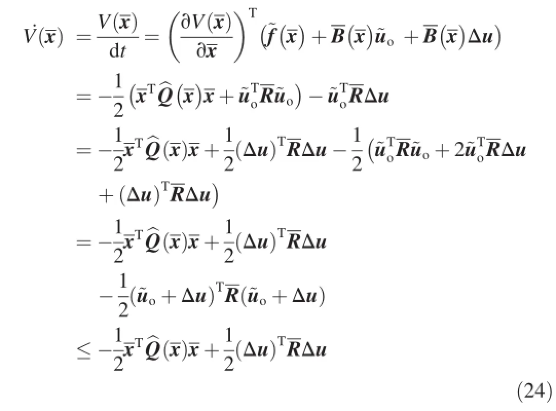

Substituting Eq.(20)and Eq.(25)into Eq.(24)yields

It follows from the inequality(17)and Eq.(26)that

6.Nonlinear optimal control solution
Theta-D technique is used to solve the nonlinear optimal control problem(B).By adding perturbations to the performance index Eq.(19),it becomes.

where Q0+Q1(x)=Q0=andx0denotes the initial states.In Eq.(28),θ is a scalar variable,Diare the perturbations.θ and Diare chosen such that Q0+Q1(x)+is positive defnite.

With Eq.(23)and Eq.(28),the HJB Eq.(22)becomes

The optimal control is given by


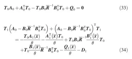
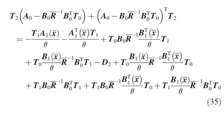
Substituting Eq.(32)into Eq.(30)and letting the coeffcients of powers of θ be zero produces the following equations:
and in general,
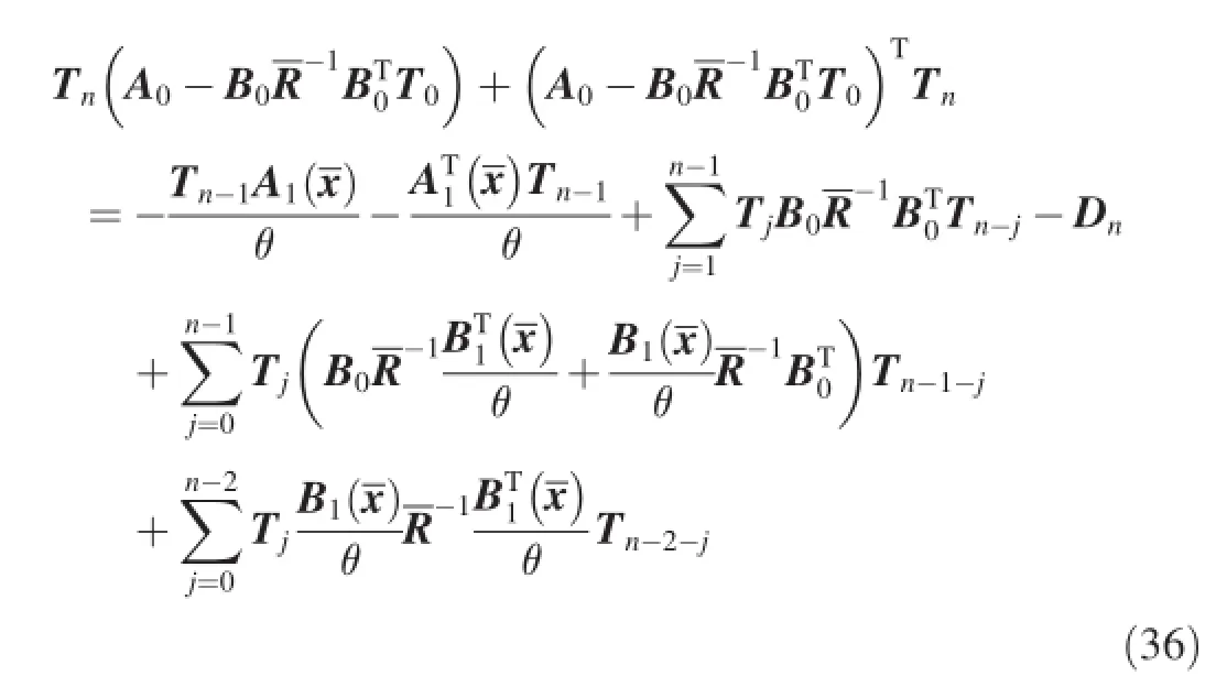
where Tidenotes Ti(x,θ)for simplicity.
The perturbation Di(i=1,2…,n)is constructed as

where

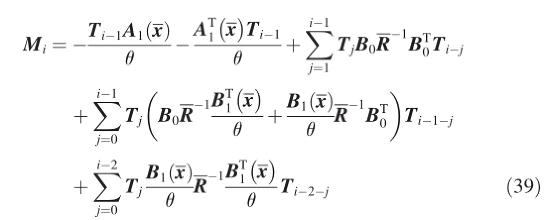
where m is the dimension of the statekia,lia(a=1,2,…m) are positive scalars;and diag{*}represents a diagonal matrix.
Eq.(33)is an algebra Riccati equation.The solution of Eq. (33)is a constant matrix T0.Eqs.(34)-(36)are Lyapunov equations which are linear in Ti.The Lyapunov equations with constant coeffcient matrix A0-have analytical solutions.After obtaining T0,the solutions Ti(i=1,2…,n)of Lyapunov equations can be obtained successively.
During the above construction,θ is just an intermediate variable and can be canceled when θiis multiplied by Tiin the calculations of fnal control.Its value can be kept as 0.1.
In practice,by taking the frst three terms in the power series expansion(32),a theta-D control is obtained as

7.Simulation
7.1.Simulation setup
Numerical results are obtained using a six degree-offreedom skid-to-turn missile model.The missile is fying at the altitude of 22 km with a speed of 1100 m/s.The dynamic coeffcients are given as follows:

The values of the coeffcients a2,a4(a′2,a′4)are obtained when the angle of attack(sideslip angle)are small.However, they gradually increase to two times their values above with α(β)increasing to|α|max=30 deg(|β|max=30 deg).
The dynamics of tail fns,accelerators and gyroscopes are modeled as second-order systems.The fn defection limit is 30 deg and the defection rate limit is 300 deg/s. The dead zone features of fn actuators are added into the models.The dynamics of pulse thruster is modeled as a zero-orderholder.The maximum ignition numberis limited to 10.
The initial states are given as x0=[0.05/57.3 -0.05/ 57.3 0 0]T.The performance of the designed autopilot is demonstrated by tracking step acceleration commands,which are approximately generated by the reference system.The initial state vector of the reference system is chosen as z0=[1 1]Tand the state matrix is selected as

where λ=1×10⁻⁶,and the output matrix is chosen as

where aycand azcdenote the desired acceleration commands and are both set to be 100 m/s2.
The weighting matrices in the tracking performance index are chosen as

The scalar γ in the modifed performance index is set to be 0.001.
According to the previous research,the positive function)in the bound of input uncertainty is chosen as a constant, i.e.,=0.75.
The terms Λi(t)in the perturbations are given as

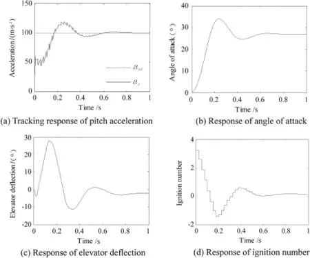
Fig.2.Pitch motion in the theta-D control.
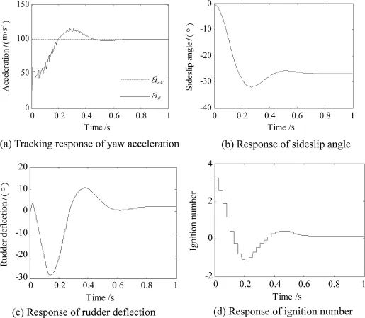
Fig.3.Yaw motion in the theta-D control.
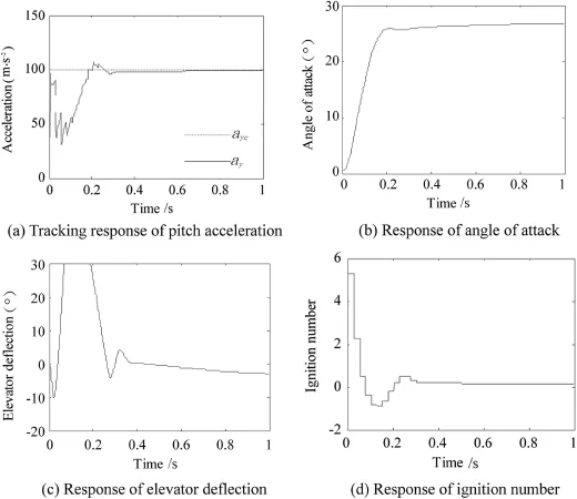
Fig.4.Pitch motion in the SDRE control.
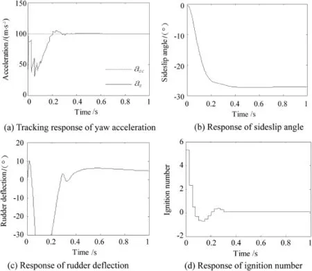
Fig.5.Yaw motion in the SDRE control.

7.2.Simulation results and analysis
The pitch and yaw motions are shown in Fig.2 and Fig.3, respectively.The motions are similar in the two planes.The tracking response of the pitch and yaw accelerations are displayed in Fig.2(a)and Fig.3(a),respectively.The pitch acceleration crosses the command at 0.17 s for the frst time while the time is 0.2 s in the yaw acceleration,and both track the command well after 0.8 s.There is no non-minimum phase phenomenon in the acceleration tracking.The pitch(yaw) acceleration achieved 50%of the command during the frst pulse period due to the large lateral thrust produced by pulse thrusters.
Although the dynamic coeffcients and weighting matrices in the pitch motion are the same as those in the yaw motion, the pitch acceleration response is faster.This is caused by the nonlinear coupling terms in Eq.(1).Meanwhile,as shown in Figs.2(b)and 3(b),the response of angle of attack is slightly faster than the response of sideslip angle.
The actual fn defections are demonstrated in Figs.2(c)and 3(c).As can be seen in the fgures,both the rudder and elevator defections do not reach their angle limits.
The ignition numbers of pulse thrusters in the two planes are shown in Figs.2(d)and 3(d).It can be seen that the maximum ignition number is 3,appearing in the frst pulse period.The ignition number brings large lateral thrust,which makes main contribution to the acceleration tracking.Since the aerodynamic forces produced by the fn defections and attitude angles are small at this time,the lateral thrust gives the major part of the acceleration of agile missile.
We applied indirect robust control strategy via SDRE control to design a missile autopilot in Ref.[12].The simulation results of the previous work are redrawn in Figs. 4 and 5.However,the weighting matrices are different from those in this paper to obtain a desired response.If the weighting matrices Eq.(43)and Eq.(44)are used in SDRE control,the acceleration commands can't be tracked within 2 s.
Compared with the results of theta-D control,the responses of the attitude angles are slower,the overshoots of the acceleration responses are smaller,and the maximum ignition number is larger.There are signifcant differences in the fn defections.As shown in Figs.4(c)and 5(c),the rudder and elevator defections both reach their limits from 0.08 s to 0.18 s.While in Figs.2(c)and 3(c),there are no such saturations.Therefore,an advantage of the theta-D control is to avoid the saturations of the fn defections.The reason to avoid the saturations lies in the requirement of splitting the state weighted matrix)into two parts,one is constant matrix and the otheris a symbolic matrix.Wethe constant part as Q0=)and the rest part of)asThis split gives suitable calculation of T0,T1,T2and then the fnal control.Neither large fn defections nor ignition numbers appear in the solution.
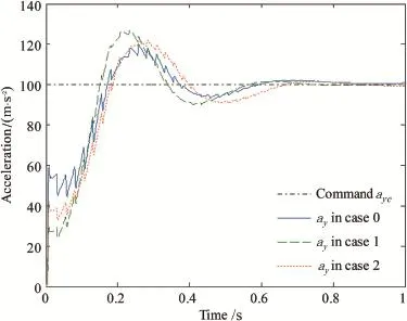
Fig.6.Pitch acceleration responses in different cases.
The new strategy not only handles the two different inputs, but also processes some robustness to parameter uncertainty due to the infuence of jet interaction[4].The infuence of jet interaction is caused by the interaction of lateral thrust with free stream aerodynamics.It leads to the changes of the moment coeffcient a6and the force coeffcient a7of lateral thrust.Let their nominal values multiply some perturbed ratios to represent the changes.In the simulation,two pairs of the perturbed ratios(case 1:1.2,0.4)and(case 2:0.8,0.7)are investigated.The nominal pair(1,1)is marked as case 0. Applying the solution obtained in case 0 to the perturbed systems,we have tested the robustness of Theta-D solution. The tracking response of the pitch and yaw accelerations are demonstrated in Fig.6 and Fig.7,respectively.
As can be seen from Figs.6 and 7,the acceleration commands are well tracked and the rising times in the two planes are both less than 0.2 s in all three cases.Since the force coeffcient of lateral thrust a7in case 1 or 2 is smaller than thatin case 0,the effectiveness of the lateral thrust in the output is weaker.Thus,the pitch(or yaw)acceleration doesn't achieve 50%of the command in case 1 or 2 during the frst pulse period.
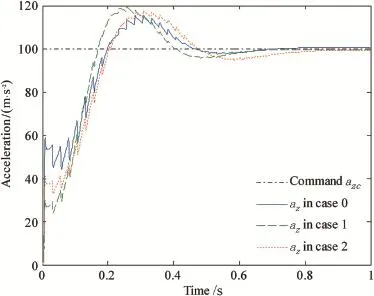
Fig.7.Yaw acceleration responses in different cases.
8.Conclusions
Indirect robust control strategy was used to design autopilot for an agile missile with tail fns and pulse thrusters.It handled the continuous and discontinuous control inputs simultaneously by constructing a robust control problem with input uncertainty.It was proved that the robust control is equivalent to a nonlinear optimal control with a modifed performance index including uncertainty bound.Theta-D approach was applied to solve the nonlinear optimal control problem to obtain a closed-form control law.Both stabilization and suboptimal tracking performance can be achieved.The numerical results have demonstrated the robust tracking performance even under parameter uncertainties due to the infuence of jet interaction.
Acknowledgment
This work was supported by the National Natural Science Foundation of China(61174203)and Aeronautical Science Foundation of China(20110177002).
[1]Xing LD,Zhang KN,Chen WC,Yin XL.Optimal control and output feedback considerations for missile with blended aero-fn and lateral impulsive thrust.Chin J Aeronautics 2010;23(4):401-8.
[2]Xu ML,Liu LH,Tang GJ,Zhu LK.Research on attitude control of kinetic energy interceptor under blended operation of lateral thrust and aerodynamic force.J Natl Univ Def Technol 2010;32(4):30-6[in Chinese].
[3]Qi NM,Li YQ,Yang Y,Gao JZ.Application of singular perturbation analysisin dualcontrol system design.JHarbin InstTechnol 2012;44(5):20-4[in Chinese].
[4]Wise KA,Broy DJ.Agile missile dynamics and control.J Guid Control Dyn 1998;21(3):441-9.
[5]Ridgely DB,Lee Y,Fanciullo T.Dual aero/propulsive missile controloptimal control and control allocation.In:AIAA guidance,navigation, and control conference and exhibit;2006.
[6]Doman DB,Gamble BJ,Ngo AD.Quantized control allocation of reaction control jets and aerodynamic control surface.J Guid Control,Dyn 2009;32(1):13-24.
[7]Zhou D,Shao CT.Dynamics and autopilot design for endoatmospheric interceptors with dual control systems. Aerosp Sci Technol 2009;13(6):291-300.
[8]Hou MY,Xie ZH,Fan HL.Control law design and simulation for high maneuveringair-to-airmissile with compound control.JBallist 2011;23(4):22-6[in Chinese].
[9]Yang BQ,Ma J,Yao Y,Cao XB.Blended control method with lateral thrust and aerodynamic force based on predictive control.J Syst Sci Math Sci 2010;30(6):816-26[in Chinese].
[10]Ma KM,Zhao H,Zhang DC.Control design and implementation for missiles with blended lateral jets and aerodynamic control systems.J Astronautics 2011;32(2):310-6[in Chinese].
[11]Li Q,Zhou D.Design of autopilot for a blended controlled missile via state-dependent riccati equation.Syst Eng Electron 2012;34(7):1445-51 [in Chinese].
[12]Li Q,Zhou D.Indirect robust control of interceptors with tail fns and pulse thrusters.In:Proceedings of IEEE International Conference on Information and Automation;2013.p.213-8.
[13]Xin M,Balakrishnan SN.A new method for suboptimal control of a class of non-linear systems.Optim Control Appl Methods 2005;26(2):55-83.
[14]Xin M,Balakrishnan SN.Nonlinear H∞missile longitudinal autopilot design with θ-D method.IEEE Trans Aerosp Electron Syst 2008;44(1):41-56.
[15]Lin F.Robust control design:an optimal control approach.Hoboken: John Wiley&Sons Ltd;2007.
[16]Meyer CD.Matrix analysis and applied linear algebra.Cambridge: Cambridge University Press;2000.
Received 10 October 2013;revised 23 April 2014;accepted 20 June 2014 Available online 22 July 2014
*Corresponding author.
E-mail address:zhoud@hit.edu.cn(D.ZHOU).
Peer review under responsibility of China Ordnance Society.
http://dx.doi.org/10.1016/j.dt.2014.06.009
2214-9147/Copyright©2014,China Ordnance Society.Production and hosting by Elsevier B.V.All rights reserved.
Copyright©2014,China Ordnance Society.Production and hosting by Elsevier B.V.All rights reserved.
- Defence Technology的其它文章
- Optimization of process parameters of the activated tungsten inert gas welding for aspect ratio of UNS S32205 duplex stainless steel welds
- Investigation on the foaming behaviors of NC-based gun propellants
- Numerical simulation of base fow with hot base bleed for two jet models
- Analysis on the resistive force in penetration of a rigid projectile
- Numerical simulation of detonation of an explosive atmosphere of liquefed petroleum gas in a confned space
- Combined proportional navigation law for interception of high-speed targets

