
Strategy to control crawling vehicles with automated mechanical transmission
2013-11-05 07:30:48WANGHongliang王洪亮LIUHaiou刘海鸥WANGJuan王娟
WANG Hong-liang(王洪亮), LIU Hai-ou(刘海鸥), WANG Juan(王娟)
(1.School of Mechanical Engineer,Nanjing University of Science and Technology,Nanjing 210094,China;2.School of Mechanical Engineering,Beijing Institute of Technology,Beijing 100081,China;3.Shandong Special Equipment Inspection Institute,Jinan 250101,China)
The vehicles have to move at a low speed to let the drivers adjust the steering wheel timely in a garage.The driver gets the low speed by clutch slipping control on the traditional mechanical transmission,which is called crawl driving[1]because of the low speed.The vehicles speed could be controlled by brake system easily for the auto transmission with hydraulic torque converter[2].But the situation become challenge for the AMT without hydraulic torque converter[3].
While initial researches on the AMT usually focused on the start control and shift control[4-8],the special functions of the AMT were ignored.Therefore,the application of the AMT technology is hindered.For example,the AMT need to start again and again when the vehicles reversed into or move in a garage.So the vehicle is hard to control because its speed changes acutely with a wave motion and the torque output to the wheels is not consistent.
Research in this paper focuses on the special function of crawl driving.Basing on the dynamic analysis of the power train system,the clutch control strategies were proposed,aimed on the low and continuous vehicle speed.The crawl driving function of the AMT was achieved based on controlling the position of the clutch accurately.At the same time,the crawl driving function was compatible with the normal start process.The development and application of the AMT technology was promoted by the function of crawl driving.
1 Dynamic analysis on the start process of the vehicle
In order to analyze the start process and get the main influence factors,the powertrain system is simplified as two free bodies:the first part in-cludes the engine and the clutch active part;the second part includes the clutch passive part,the transmission and the wheel[9].Fig.1 shows the model of the power train system.
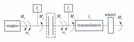
Fig.1 Dynamic model of power train
Meis the torque output by the engine.Mcis the torque transported by the clutch.Mris the resistance torque caused by the ground.The torque loss Miare the results of bearing losses,oil churning losses and oil drag losses,etc.ωeis the rotation velocity of engine.ω1is the rotation velocity of the transmission input shaft.Ieis the moment of inertia on the clutch axis caused by all the masses involved,such as the cranks and links of the engine.Iois the moment of inertia on the clutch axis caused by all the masses involved,such as the transmission and whole of the vehicle.iois the ratio of the transmission.
According to different working conditions of the clutch,the start process is divided into three stages:
①The stage of eliminating the gap between the two parts of the clutch.
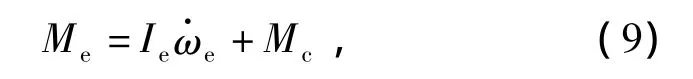
The torque affected on the engine is described as

At this time,there is no torque transported by the clutch,so the torque produced by the engine is only used to change its own speed.There is also no torque caused by the ground.Therefore,

②The stage of the clutch slipping.
The torque affected on the engine is described as

In this stage,Mcis slipping friction torque because the clutch is slipping.
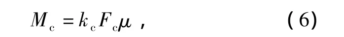
where kcis the area of the working surface.Fcis the compaction force between the two parts of the clutch.μ means the friction coefficient of the clutch.
The slipping friction torque Mcis decided by the force Fcbetween the two parts of the clutch,with the knowledge from Eq.(6).The torque affected on the transmission is described as

So the slipping friction torque Mcdepends on,which is the acceleration of the rotation velocity of the transmission input shaft.
③The stage after synchronization.
In this stage,the rotation velocity of the transmission input shaft is the same with the rotation velocity of the engine,
where Mcis the static friction torque which affected on the transmission,because the clutch is synchronized.The torque Mcis described as

The torque transformed from slipping friction torque to static friction torque at the synchronization point,which ends the second stage and starts the third stage of the start process.
2 Analysis on the requirements of crawl driving
There are two requirements for crawl driving.First,the vehicle should move at a speed smaller than the lowest speed when the engine was idling and the transmission ratio was the largest.Secondly, themoving speed should be steady.
In order to meet the requirements of crawl driving,there are some special requirements for the clutch control.At first,the slipping friction torque Mctransported by the clutch should be larger than the resistance torque in order to let the vehicle start to move:

At the same time,the acceleration occurred:
The second,the slipping friction torque Mcshould be the same as the resistance torque in order to keep the speed stable,after the vehicle starting to move:
In order to achieve the crawl driving,the speed should increase to a certain value and then keep stable.So the torque transported by the clutch should increase in the beginning and decrease lately.
In the start process,at first the speed increases with the engaging of clutch.And then the clutch turns to disengage until the torque transported by the clutch is equal to the resistance torque,when the speed increases to a special value.
The target clutch position of disengaging is very important for the crawl driving control.The vehicle speed will decrease,if the friction torque transported by the clutch is smaller than the resistance torque.Otherwise the speed will increase,if the slipping friction torque transported by clutch is larger than the resistance torque.None of the aforementioned cases can meet the requirements of crawl driving.
In the start process,the position of the clutch where the slipping friction torque is equal to the resistance torque is called the clutch half joint.The clutch half joint is considered to be the position that the vehicle starts to move.
The position of the clutch half joint differs because ofthe differences ofthe resistance torque.But the influence of the resistance torque on the clutch half joint could be ignored because the moving distance is short in a crawl driving course.
To keep the moving speed smoothly,the position of the clutch half joint located before should be taken as the target of disengaging.
3 Control strategy for the crawl driving
Fig.2 shows the ideal clutch control curve of crawl driving.According to the aforementioned requirements,the start process is divided into four stages[10].The first stage,the clutch engages rapidly to eliminate the gap between the two parts of the clutch.The second stage,the speed and acceleration of the vehicle appears.The clutch engages slowly until the speed meeting the requirements of crawl driving.The required speed of crawl driving is set to let the driver have enough time to turn the steering wheel.So the aim is set by experience,which is recommended for 3-5 km/h.The aimed speed could also be adjusted by the requirements of different vehicles.The third stage,the clutch turns to disengage until the clutch reaching the clutch half joint again.The fourth stage,the clutch is maintained at the half joint to keep the speed smooth and low.The position of clutch could also be adjusted,if the speed doesn’t meet the requirements of crawl driving attributed to the changes of the resistance.

Fig.2 Ideal control curve for clutch
The crawl driving is used when the vehicle drives in a flat garage where the resistance is small,so the crawl driving occurs only when the engine work at the idle state or a low speed.The vehicle shouldn’t work in crawl driving if the vehicle drives upon a hill,because it causes serious friction on the clutch and reduce the life of the clutch.At the same time,in order to prevent the clutch from long time slipping,the slipping time should be limited.The crawl driving ended after a few seconds.Or the vehicle still keeps crawl driving when the driver intervenes.
4 Software diagram for the crawl driving
Fig.3 describes the software diagram of crawl driving.The software is designed according to the aforementioned control strategy.Firstly,the clutch engages rapidly to the clutch half joint point.Then the clutch engages smoothly until the speed of vehicle meets the requirements of crawl driving.Thirdly,the clutch turns to disengage until the clutch reaches the half joint point again.In the end,the position of the clutch adjusts according to the vehicle speed.
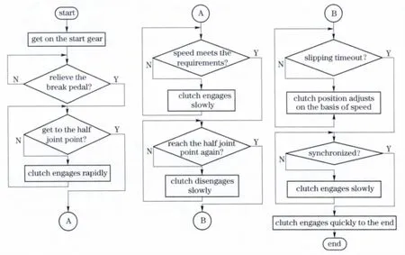
Fig.3 Software diagram of crawl driving
5 Test
The software designed in section 4 is tested on a vehicle with AMT.Fig.4a shows the data of crawl driving.Fig.4a shows the case of a single crawl driving,and Fig.4b shows the case of continuous crawl driving.
In Fig.4a,when the vehicle starts to move,the speed appears and increases when the clutch engaging.The clutch turns to disengage until the clutch reaches the half joint point again,when the speed of the vehicle meets the requirements of crawl driving at 60.1 s.The position of the clutch reaches the half joint point at 60.4 s again,and then the clutch remains at the current location.At the same time,the vehicle comes into crawl driving status with a low and smooth speed.The rotation speed of the input shaft is 500 r/min,which is less than the idling rotation speed of the engine(800 r/min).The vehicle turns to normal start process when the slipping time of the clutch exceeds the limits time.The clutch begins to engage slowly until synchronization,and then the start process is finished.The crawl driving showed in Fig.4a is used to move the vehicle a little bit distance once or start the vehicle normally.
In Fig.4b,the vehicle keeps the crawl driving status continuously for about 20 s,because of the intervention of the driver in the start process.The average rotation speed of the input shaft is 300 r·min-1,which is reduced by 60%than the lowest speed of the engine(800 r·min-1)after synchronization.The speed is smooth and low,so it’s suitable for the vehicle to be reversed into garage or moved in the garage.The crawl driving showed in Fig.4b is used to move the vehicle a bit longer distance once.
The crawl driving control strategy is proved to be useful by the data in Fig.4.The vehicle moves lowly and smoothly by the crawl driving strategy,so it is safe and easy to drive.

Fig.4 Data of the crawl driving
6 Conclusion
The research is focuses on the crawl driving of the vehicle with AMT.Based on the special requirements of crawl driving and the dynamic analysis on the start process,the requirements of clutch control for crawling control is proposed,and the controlstrategies ofthe clutch are brought forward.The software is designed and tested.It has been proven to be useful for vehicles moving in small distance.
[1] He Zhongbo,Chen Huiyan,Xi Junqiang,et al.The control strategy and experimental research of an AMT vehicle’s clutch in crawl driving condition
[J].Automotive Engineering,2003,25(6):574-577.(in Chinese)
[2] Xu An,Qiao Xiangming.Study on driving technique forvehicleswith automatictransmissionsunder some specific conditions[J].Automobile Technology,2004(10):36 -39.(in Chinese)
[3] Wang Hongliang,Liu Haiou,Chen Huiyan.Automatic shift control system(ASCS)in OFF-road vehicles[J].Transactions of Beijing Institute of Technology,2009,29(3):214-217.(in Chinese)
[4] Xi Junqiang,Chen Huiyan,Ding Huarong.Feasibility research on ASS drived by DC motor[J].Vehicle&Power Technology,2001(2):1-5.(in Chinese)
[5] Tang Xiaqing,Hou Chaozhen,Chen Yunchuang.Study of controlling clutch engagement for AMT based on fuzzy logic[J].Journal of Beijing Institute of technology,2002,11(1):45-49.
[6] Jiang Fachao,Chen Quanshi,Cao Zhengqing.Optimal control of automated mechanical transmission clutches[J].Journal of Tsinghua University:Science &Technology,2005,45(2):242-245.(in Chinese)
[7] Liu Haiou,Chen Huiyan,Ding Huarong,et al.A-daptive clutch engaging process control for automatic mechanical transmission[J].Journal of Beijing Institute of Technology,2005,14(2):170-174.
[8] Tseng Ch,Hsieh Mif.Analysis and optimization of clutch actuator on automated manual transmission syatem[C]∥SAE World Congress&Exhibition.Detroit,MI,USA:SAE,2005:903 -909.
[9] Wang Hongliang,Liu Haiou,Zhao Xijun,et al.Start control strategy for the diesel engine with variable-speed governor in heavy commercial vehicle[J].Automotive Engineering,2009,31(8):756 -760.(in Chinese)
[10] Wang Hongliang,Zhao Xijun,Liu Haiou.The electronic-pneumatic hill-starting assistcontrolfor heavy-duty vehicles with AMT[J].Journal of Shandong University:Engineering Science,2009,39(5):79-83.(in Chinese)
猜你喜欢
Chinese Physics B(2024年1期)2024-01-25 07:12:40
小哥白尼(野生动物)(2022年5期)2022-08-15 08:46:20
学校教育研究(2022年1期)2022-03-22 02:45:06
Chinese Physics B(2021年11期)2021-11-23 07:32:26
Chinese Physics B(2021年10期)2021-10-28 07:09:36
健康之家(2021年19期)2021-05-23 09:10:44
山东国资(2021年12期)2021-03-12 10:04:30
阅读与作文(小学高年级版)(2015年12期)2015-05-30 10:48:04
中国工程咨询(2015年4期)2015-02-14 03:50:08
小天使·五年级语数英综合(2014年6期)2014-07-29 21:36:00
 Journal of Beijing Institute of Technology2013年2期
- Journal of Beijing Institute of Technology的其它文章
- Self-diagnosis method for faulty modules on wireless sensor node
- Optical micro-scanning location calibration of thermal microscope imaging system
- Multiple-impairment monitoring for optical duobinary system based on delay-tap asynchronous sampling
- Experimental study on durability fracture behavior and vibration modal sweep for vehicle rear axle
- Control strategy for hybrid tracked vehicles using fuzzy logic
- Roundness error evaluation by minimum zone circle via microscope inspection