
Failure behavior of highly stressed rocks under quasi-static and intensive unloading conditions
2013-10-19 06:58JieLiPengxianFanMingyangWang
Jie Li , Pengxian Fan, Mingyang Wang
aState Key Laboratory of Disaster Prevention and Mitigation of Explosion and Impact,PLA University of Science and Technology,Nanjing,Jiangsu 210007,China
bSchool of Mechanical Engineering,Nanjing University of Science and Technology,Nanjing,Jiangsu 210094,China
cCollege of Field Engineering,PLA University of Science and Technology,Nanjing,Jiangsu 210007,China
1.Introduction
With increasing depth of underground structures,in situ stresses become higher,which may lead to change of rock properties.In presence of excavation disturbance,rock mass at great depth presents some abnormal behaviors,such as rockburst,zonal disintegration(Shemyakin et al.,1986),anomalous low friction,and pendulum-type wave phenomena(Wu et al.,2009a).Highstress state and artificial disturbances(i.e.explosion,excavation unloading,or changes of boundary conditions)are believed to be the most important factors in the evolution process of deformation and failure of rocks.
Since the concept of unloading rock mechanics was proposed by Ha (1997), failure behavior of rocks has been one of the hot issues in rock mechanics.Experimental results(Li et al.,2001,2010;Huang and Huang,2008,2010;Qiu et al.,2010)indicate that in case of unloading,rock strength tends to decrease and tensile failure is more likely to occur.In some theoretical analyses,the influence of initial stress,as well as unloading speed,was studied(Wang et al.,2010;Fan et al.,2010a,b).Analytical results reveal that the failure mode of surrounding rock is governed by the initial stress level and unloading intensity.In addition,the mechanism of zonal disintegration of tunnel surrounding rocks was also widely investigated(Metlov et al.,2002;Wang et al.,2006;Qian and Li,2008;Wu et al.,2009b).However,the zonal disintegration of rocks ahead of working face was not paid enough attention to.
Moreover,the effect of strong dynamic unloading of stressed rocks has also been focused on(Lu et al.,2011,2012;Yan et al.,2012).The failure behaviors of brittle rock under intensive unloading have been observed in laboratory tests(Bauch and Lemmp,2004;Chen et al.,2012)and field investigations(Yan et al.,2009).According to their results,the damaged zone of surrounding rocks is much larger than that under the quasi-static loading condition.However,due to the complexity of multi-factor coupling,the unloading failure mechanism of rock mass at great depth remains unknown.The paper attempts to reveal some common characteristics of unloading failure process of highly stressed rocks.Two unloading patterns,quasi-static and intensive unloadings,are considered on the basis of some assumptions for simplicity,which are helpful in understanding the physical nature of unloading fracture of rocks.
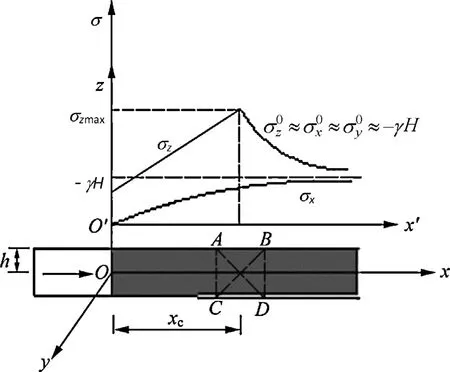
Fig.1.Stress distribution of rock ahead of working face.
2.Quasi-static failure of rocks
It is known that stress will be redistributed in the vicinity of working face during excavation.The increasing deviatonic stress induces irreversible deformation or failure of rocks. Sometimes, the rock ahead of working face is broken into blocks with a hierarchical structure.The size characteristics(Qi and Qian,2009)determine the post-peak trend of rock mass,while the frictional properties between rock blocks determine the residual strength of rock mass.
2.1.Problem definition
In this paper,a simplified plane strain problem is targeted to investigate the failure characteristics of rocks ahead of working face.The real stress distribution of rocks is undoubtedly in three dimensions;thus,a mathematical simplification is needed for analytical solutions.
Under the plane strain condition,the stress field,deduced by elastoplastic model,of rock mass ahead of the working face is demonstrated in Fig.1.In Fig.1,σ is the stress,γ is the unit weight of overlying rocks,H is the buried depth of the tunnel,and h is the half height of the tunnel.
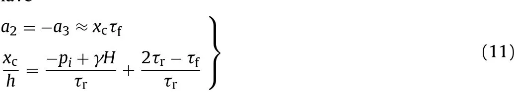
Suppose that,at time t=0,the rock mass is under hydrostatic compression by gravitational stress of σ0=-γH in initial state.After rocks are unloaded,there are basically two zones ahead of working face.One is the irreversible deformation zone and the other is the elastic zone,which are separated by the section x=xc.The balance equation is
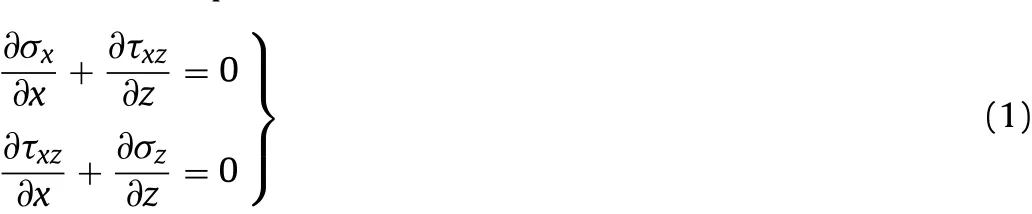
In consideration of the brittleness of rock,an elasto-brittle model is adopted in the analysis.As shown in Fig.2,the relationship between the maximum shear stress and the maximum shear strain is linear in pre-failure zone.When the principal shear stress satis fies Tresca criterion,the rock fails and the shear stress drops to residual strength.where τfis the maximum shear strength.
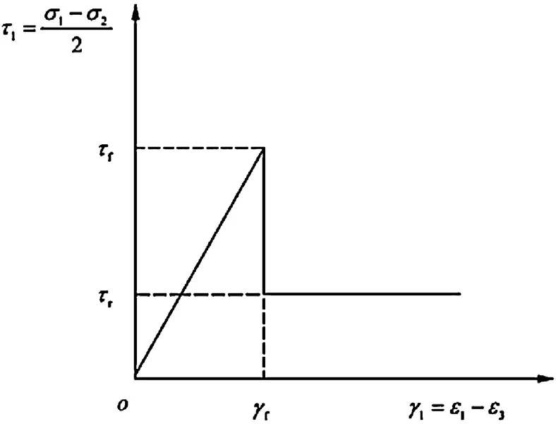
Fig.2.Relation between maximum shear stress and maximum shear strain distortion.
After rock failure,the shear stress drops from the maximum shear strength τfto residual shear strength τr,thus rock blocks and slip network are formed.Within the irreversible deformation zone,i.e.the failure zone,the stresses can be written as

In plane xoz,the relations between strains and displacements can be written as

where u,w are the displacements along x and z,respectively;εx,εzare the normal stains along x and z,respectively;and γxzis the shear strain.
2.2.Stress-displacement distribution
In case of h≪H,the stress state of rock mass in the vicinity of working face can be represented by Prandtl’s solution(Yu,2006)for thin compressed layer as
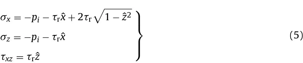
where piis the pressure acting on the compressed layer;ˆx andˆz are the dimensionless parameters,and we haveˆx=x/h,ˆz=z/h.
At free boundary,according to Saint-Venant principle,we have

Substituting σxinto Eq.(6),we get

The stress state of elastic zone can be determined by Hooke’s law and stress function method.The Hooke’s law can be written as
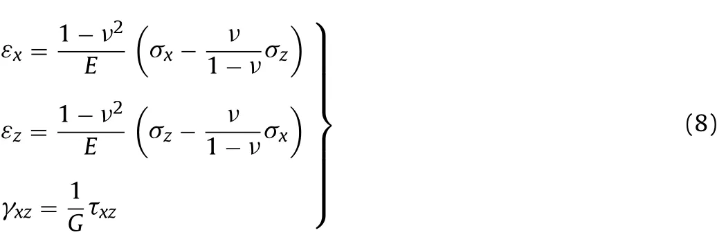
where E is the Young’s modulus,ν is the Poisson’s ratio,and G is the shear modulus.
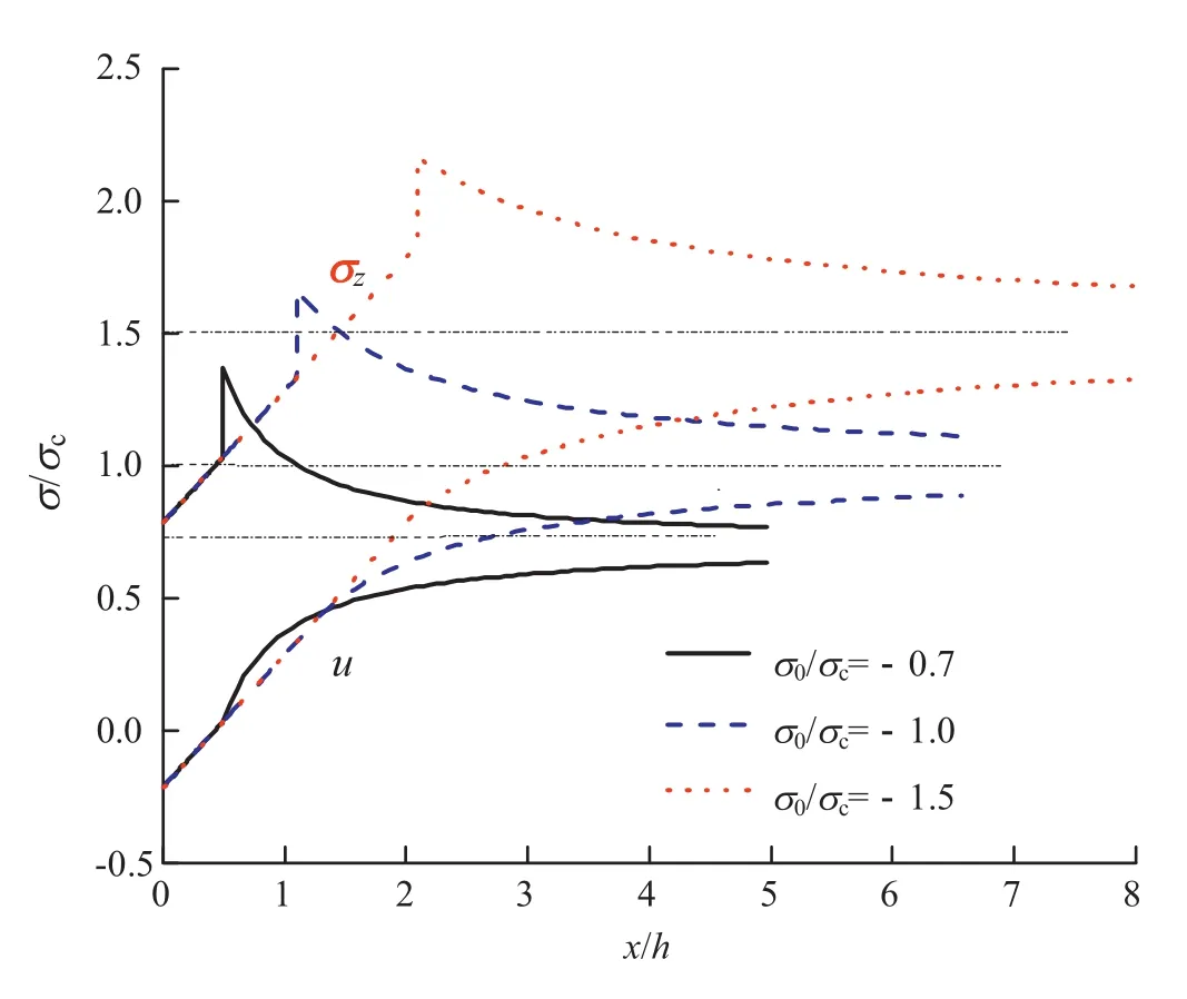
Fig.3.Distribution of stress σzand displacement u for different initial stresses.
The solution(Li,2012)to Eq.(8)is
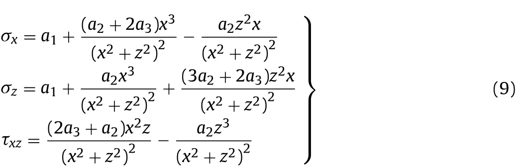
where ai(i=1,2,3)is the unknown coefficient and can be determined by boundary and continuity conditions.

Let x→∞,it is noted that σx=σz=-γH,thus we have In the contact zone between failure zone and elastic zone,the rock stress is in balance state,thus the stress σxin Eqs.(5)and(9)is identical when x=xc.Meanwhile,the rock material on the separatrix satis fies the Tresca criterion as given in Eq.(2).Thus we have
The peak stress can be computed by

As an example,let h=3m,E=5GPa,ν=0.25,τs=15MPa,τf=20MPa,and the initial stress,σ0,is assumed to be 21MPa,30MPa and 45MPa.The distributions of stress σzand displacement u are shown in Fig.3.
From Fig.3 we can see that in all the three cases,the stress σzundergoes a jump-up,while the displacement u almost keeps constant.As the initial stress increases,the peak value of σzincreases,and the catastrophe point of stress appears far from the working face(in other words,the values of x/h increases).Additionally,the peak value of σzis much larger than the initial stress,and thus in the peak stress area,the rock mass may be fractured.
2.3.Conditions for tensile fracture of peak stress area
For simplicity,we choose the middle section with peak stress as an example,i.e.the rectangle ABCD illustrated in Fig.1.As the
working face advances,the stress state of rectangle ABCD undergoes three states shown in Fig.4 subsequently.When the working face leaves,the rectangle ABCD is under the state of hydrostatic stress.As the working face advances,the distance between working face and rocks in the rectangle ABCD decreases.The stress state of the material in the rectangle ABCD gradually transforms from initial stress state to that of the peak stress zone.At last,the rectangle ABCD will locate in the neighborhood of the free face,and the boundary line AC acts as the working face,as shown in Fig.4c.
According to Qian et al. (2011), the main causation of volumetric change of rocks in the vicinity of working face is likely to be the layer splitting. In the peak stress area, the value of σzis several times that of σx(or σy).When σxand σyare regarded as confining pressures,the tensile strain will develop and the tensile failure of peak stress area is likely to occur.The material in the peak stress area tends to be cracked,forming structure-like pillars or pseudo working face,which is believed to be the main reason of volumetric dilatation.According to field observations,the displacement of working face is much larger than the predicted value by elastoplastic theory.
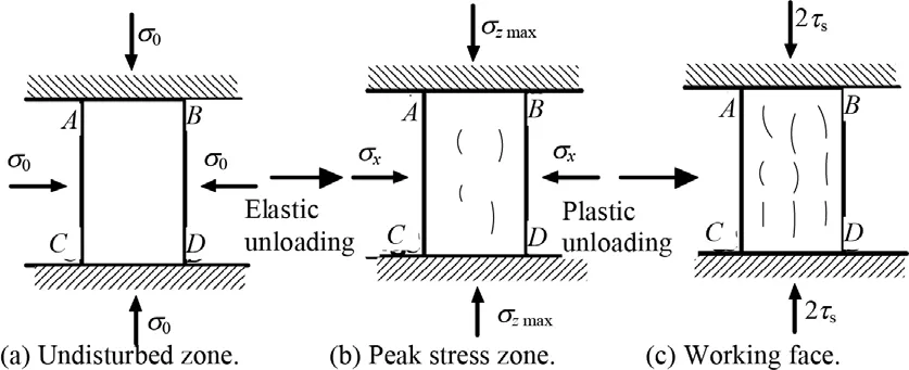
Fig.4.The evolution of stress state as working face advances.

In tensor form,the stress can be expressed as where σijis the stress tensor,δijis the Kronecker delta,p is the average stress,and Sijis the deviatoric stress tensor.

The adopted constitutive model can be expressed as where Kpis the unloading volumetric modulus with consideration of dilation.
Assuming that the plastic volumetric deformation is uncompressible,i.e.dεpijδij=0,the volumetric deformation can be expressed as

It is noted that rock mass in depth has been subjected to high compressive stress for millions of years. The volumetric modulus of the material can be regarded as a constant K,which is the maximum volumetric modulus.During unloading,plastic deformation develops and the material is broken into blocks along the slip lines.The unloading volumetric modulus Kpis a varying parameter because of dilation and the failure of the material, and it relates to the degree of damage of rocks.However,there are few reports on this issue.In our analysis,the volumetric modulus is generally determined by interpolation.
In the present analysis of rock deformation, the boundaries in y and z-directions are confined,and the strain along x-axis induced by dilation is
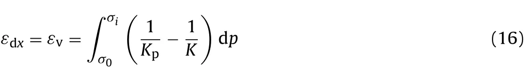
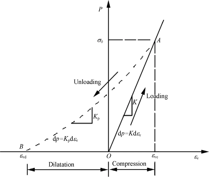
Fig.5.Loading and unloading deformation processes of rocks.
where σiis the average compressive stress acting on the rectangle ABCD.When the rectangle ABCD is located on the working face,σireaches its minimum value-τr.Thus we have
The strain induced by elastic deformation is

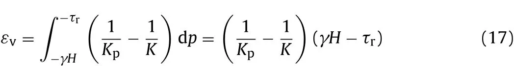
Assuming when εdx+ εex≥ εtis satisfied,in which εtis the tensile strain limit of material,rocks fail.Therefore,the condition for the tensile fracture of rocks can be expressed as
where γfis the shear strain when rock breaks.
Eq.(19)implies that the critical condition for the tensile fracture of rock ahead of the working face mainly relates to the shear strength,the tensile strain limit,the shear modulus and the volumetric modulus of rocks.Fig.5 shows the relationship between the volumetric stain and compressive stress during loading and unloading.In the isotropic compression process of rocks,the volumetric modulus is approximately linear, and the bearing capacity of rocks is significantly increased.However,under unloading condition,rock mass tends to fracture more easily and undergoes larger volumetric strain(expansion).If rocks fail during the unloading process,the volumetric strain will be in the tensile(left side of Fig.5)region of the coordinate of pressure and volumetric strain.
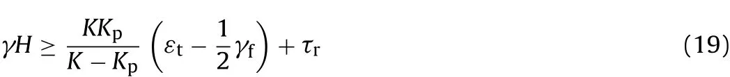
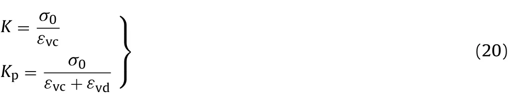
Generally,unloading process is nonlinear. However, for simplicity,we will adopt a linear approximation of unloading process and consider the volumetric modulus as a constant.Thus,we have whereεvcis the volumetric strain under compressive stressσ0,and εvdis the dilatation strain when the stress is unloaded to zero.
From Eq.(20),we have

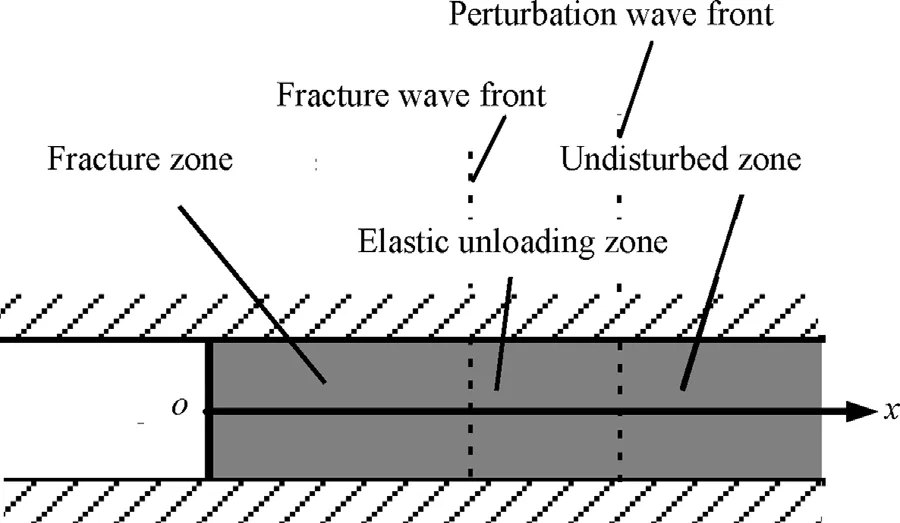
Fig.6.Sketch of intensive unloading.
Thus,Eq.(19)can be rewritten as
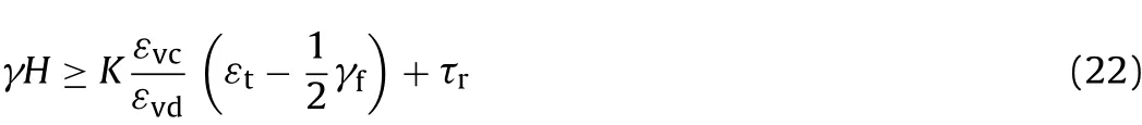
Eq.(22)implies that the stress condition for quasi-static unloading tensile failure of rocks is closely related to the fracture dilatation characteristics which are controlled by material deformation parameters.However,literature about the post-peak deformation of rocks is rarely reported.
3.Intensive unloading induced fracture
For the problems of intensive unloading of highly stressed rock,we can suppose an ideal particulate material being located between two smooth, absolutely rigid parallel flat planes (see Fig. 6). The particles are closely packed in the defined space by high in situ stresses.The x-axis is parallel to the plane and the material occupies the region x>0.For simplicity,it is assumed that the material is brittle and linearly elastic.In fact,this one-dimensional(1D)problem is identical to the unloading of a semi-in finite plane.
It is supposed that,at time t=0,the material in the half space x>0 is in equilibrium state and under hydrostatic compression by stress σ0=γH.When x=0 and t>0,the stress at the boundary x=0 is released abruptly.After the instantaneous unloading of external loads,a perturbation wave will propagate from the free boundary.If the pressure σ0is sufficiently high,the loading perturbation wave will be followed by a fracture wave(Cherepanov,1979).The velocity of the fracture wave can be determined by solving the 1D problem.
The fracture wave is derived by the potential energy of elastic compression.When the necessary conditions are satisfied,the fracture wave is self-sustained. The possibility and intensity of self sustained fracture depend on the amount of potential energy.
Similarly,the unloading process of highly stressed rock consists of two unloading waves.The first is the elastic unloading wave,which propagates from the free boundary with a velocity identical to the elastic compression wave and unloads the material to a certain lower stress state σc,i.e.the critical stress for unloading fracture.The second is the fracture wave,which unloads the material to the destination stress state σd.In other words,the unloading wave will be split into an elastic unloading wave and a fracture wave when unloading intensity is sufficiently strong.Thus,the region x>0 can be divided into three zones:fractured zone,elastic unloading zone and undisturbed zone(see Fig.6).Fig.7 demonstrates the unloading process of highly stressed rocks,in which ceand cfare the velocities of elastic compression wave and fracture wave,respectively.
In the following analysis,it is assumed that the deformation of unbroken material is small and the fracturing is an irreversibleprocess.Mass conservation equation,momentum conservation law and energy conservation law of fracture surface can be written as
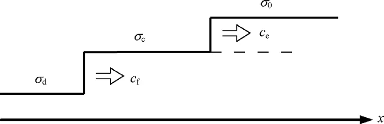
Fig.7.Decomposition of unloading wave.
(1)Mass conservation equation:

(2)Momentum conservation law:

(3)Energy conservation law:

In the above three equations,ρ is the density of material,υ is the particle velocity,U is the elastic potential of unit mass,and D is the energy dissipated in the fracture process of unit mass,subscripts“0”and “F”stand for the elastic unloading zone and the fractured zone,respectively.
Combining Eqs.(23)-(25),noting that υ0≪υF,and ρ=ρ0=ρF,the dissipative energy D can be determined:

In the 1D problem,the motion equation of material is

where u is the displacement.
The physical state in the elastic unloading zone is expressed as
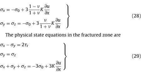
In the fractured zone,the shear deformation is plastic and the volumetric deformation is elastic.The strain state of the material can be expressed as

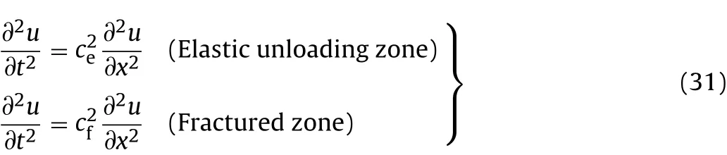
Substituting σxin Eqs.(28)and(29)into Eq.(27),the following equations can be derived:
where
The energy accumulated in unit mass of elastic unloading zone can be expressed as
The energy stored in unit mass of fractured zone consists of two components:the elastic energy induced by the volumetric strain and the deformation energy induced by shape change.Then,we have
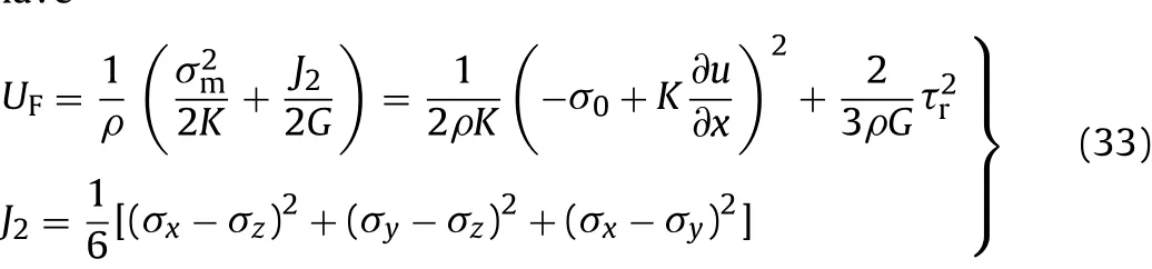
where σm=(σx+σy+σz)/3 is the average stress.
If the dissipative energy D is regarded as a material constant,the critical condition of self-sustained fracture can be given by theoretical analysis.According to the compatibility of characteristic lines,two displacement fields of fracture process can be established.The solution to Eq.(31)is
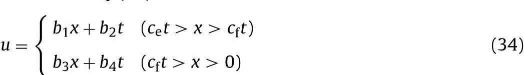
where bi(i=1,2,3,4)is the unknown coefficient,which can be determined by the displacement continuity condition,momentum conservation law and boundary condition in the area where the material state changes.
The displacement continuity condition is

The momentum conservation laws can be expressed as
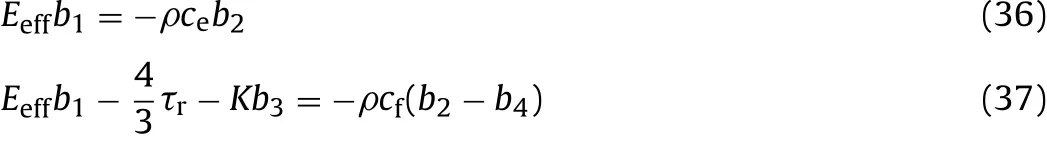
The stress boundary condition of free surface is

Eqs.(35)-(38)actually can make up an equation set with four unknowns.The solution for the unknowns is
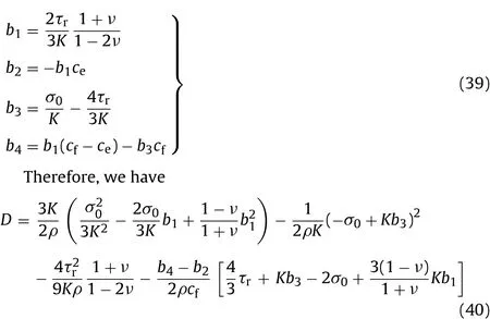
Substituting Eq.(39)into Eq.(40),the self-sustained fracture stress condition can be obtained:

Eq.(41)implies that the stress condition for self-sustained fracture under intensive unloading condition is related to energy dissipation in fracture process, as well as the shear strength and the Poisson’s ratio.If the dissipative energy in fracture process is D=0,i.e.the material is comprised of compacted cohesionless particles,the critical stress can be expressed as

4.Discussion
The unloading failure of highly stressed rock(core discing,spalling,rockburst,etc.)is a very common phenomenon in engineered rock mass at great depth. Although it remains unclear,many researchers(Lajtai,1998;Hajiabdolmajid et al.,2002;Suknev,2008;Feng et al.,2012)tended to believe that the failure of brittle rock is dominated by tensile fracture at the beginning,especially under unloading condition.The representation of tensile fracture is determined by the initial stress state and the unloading mode.
Actually,the proposed quasi-static unloading failure problem is a simplified form of zonal disintegration phenomenon with only one tensile fracture zone.And the proposed intensive unloading fracture mode possibly occurs in drill-and-blast process and has close relations with instantaneous strain rockburst.
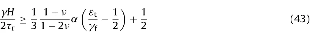
Dividing Eq.(22)by 2τrand assuming α=εvc/εvd,Eq.(22)can be rewritten as
Similarly,dividing Eq.(41)by2τrand as sumingσ0=γH,wehave

Eqs.(43)and(44)are the dimensionless stress conditions for quasi-static and intensive unloading fracture of highly stressed rocks.An example is presented for this issue.The Poisson’s ratio is assumed to be 0.2.The results are shown in Fig.8.From Fig.8,we can conclude that:(1)the stress required for dynamically self-sustained fracture is higher than that for quasi-static tensile fracture;and(2)among the factors,the ratio of residual shear strength to ultimate shear strength has the most important impact, while the ratio of ultimate tensile strain to ultimate shear strain has a minor influence.
The zonal disintegration phenomenon has been widely studied(Odintsev,1994;Qian and Li,2008;Qi et al.,2011),and some researchers have reported the stress conditions in their observations or analytical studies(Adams and Jager,1980;Wang et al.,2006;Li et al.,2008).Generally,zonal disintegration is observed under the condition of γH/σc>1,which is somewhat higher than the quasi-static unloading failure condition.However,no specificinvestigation on the stress condition for zonal disintegration of rock ahead of working face is reported.
The intensive unloading fracture of rocks can be characterized in terms of susceptibility of a particular rock to self-disintegration,which is closely related to rockburst.Self-disintegration is possible when the amount of specific elastic energy stored in the material under peak strength load is equal to or exceeds the specific energy absorbed by the rock material while undergoing deformation and rupture during the post-failure phase.A model experiment has already been conducted to simulate the intensive unloading behavior of rocklike materials (Chen et al., 2012), and a fracture wave was observed when the highly stressed material was instantaneously unloaded.
Someone may argue that the model presented is over-simplified and some factors are not considered,such as stress path effect and unloading rate effect, from a practical point of view. The results can give us some basic insight into the unloading fracture process.The results suggest that the post-peak deformation or strength characteristics of rocks,i.e.the strain softening of rocks,especially the unloading deformation properties,should be paid more attention to in further study.
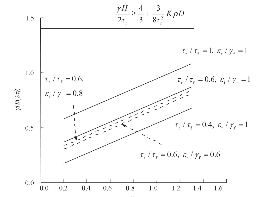
Fig.8.The dimensionless stress conditions for quasi-static and intensive unloading fracture of highly stressed rocks.
5.Conclusions
Two extreme unloading conditions are considered in this paper.Theoretical analysis demonstrates the tensile nature of the fracture of brittle rock under quasi-static and intensive unloading conditions.The results can be drawn as follows:
(1) Quasi-static unloading of highly stressed rock ahead of working face will induce stress redistribution and form a peak stress area.If certain conditions are satisfied,the rock in peak stress area tends to be fractured.The stress condition mainly relates to the tensile strain,the shear strain,especially the post-peak softening characteristics of rock.
(2)If highly stressed rock is unloaded intensively,an elastic unloading wave followed by a fracture wave will propagate in the material.The critical initial stress for the formation of fracture wave is much higher than that of quasi-static unloading failure,and governed by the disintegration dissipative energy.
Acknowledgements
This research is sponsored by the National Science Fund for Distinguished Young Scholars(50825403),the National Key Basic Research Program of China(2010CB732003,2013CB036005),and the Science Fund for Creative Research Group of the National Natural Science Foundation of China(51021001).
Adams GR,Jager AJ.Petroscopic observations of rock fracturing ahead of stope faces in deep-level gold mine.Journal of the South African Institute of Mining and Metallurgy 1980;44(6):204-9.
Bauch E,Lemmp C.Rock splitting in the surrounds of underground openings:an experimental approach using triaxial extension test.In:Hack R,Azzam R,Charlier R,editors.Engineering geology for infrastructure planning in Europe.Berlin:Springer;2004.p.244-54.
Chen W,Song C,Cheng T,Xiao Y.On the rockburst model experiment based on similar material and the energy releasing mechanism.Journal of Experimental Mechanics 2012;27(5):630-6[in Chinese].
Cherepanov GP.Mechanics of brittle fracture.New York:McGraw-Hill;1979.
Fan P,Wang M,Li W,Chen M.Time effect of stress and deformation of surrounding rock of circular tunnels during unloading.Rock and Soil Mechanics 2010a;31(Suppl.1):28-34[in Chinese].
Fan P,Wang M,Qian Q.Time effect and main influence factors of unloading splitting of deep-seated rock with nonuniformities.Chinese Journal of Rock Mechanics and Engineering 2010b;29(7):1389-96[in Chinese].
Feng X,Chen B,Ming H,Wu S,Xiao Y,Feng G,et al.Evolution law and mechanism of rockbursts in deep tunnels:immediate rockburst.Chinese Journal of Rock Mechanics and Engineering 2012;31(3):433-44[in Chinese].
HaQ. Rock slope engineering and unloading nonlinear rock mass mechanics. Chinese Journal of Rock Mechanics and Engineering 1997;16(4):386-91[in Chinese].
Hajiabdolmajid V,Kaiser PK,Martin CD.Modelling brittle failure of rock.International Journal of Rock Mechanics and Mining Sciences 2002;39(6):731-41.
Huang R,Huang D.Experimental research on affection laws of unloading rates on mechanical properties of Jinping marble under high geostress.Chinese Journal of Rock Mechanics and Engineering 2010;29(1):21-33[in Chinese].
Huang R,Huang D.Experimental research on mechanical properties of granites under unloading condition.Chinese Journal of Rock Mechanics and Engineering 2008;27(11):2205-13[in Chinese].
Lajtai EZ.Microscopic fracture processes in a granite.Rock Mechanics and Rock Engineering 1998;31(4):237-50.
Li J,Xiong J,Yang X.Experimental investigation on unloading mechanical characteristic of rock mass.Water Resources and Hydropower Engineering 2001;32(5):48-51[in Chinese].
Li J.Research on the unloading mechanical mechanism of deep rock mass and its constitutive model.Nanjing:PLA University of Science and Technology;2012[PhD thesis;in Chinese].
Li S,Wang H,Qian Q,Li S,Fan Q,Yuan L,et al.In-situ monitoring research on zonal disintegration of surrounding rock mass in deep mine roadways. Chinese Journal of Rock Mechanics and Engineering 2008;27(8):1545-53[in Chinese].
Li J,Wang L,Wang X,Wang R,Cheng Z,Dang L.Research on unloading nonlinear mechanical characteristics of jointed rock masses.Journal of Rock Mechanics and Geotechnical Engineering 2010;2(4):357-64.
Lu W,Yang J,Chen M,Zhou C.Mechanism and equivalent numerical simulation of transient release of excavation load for deep tunnel.Chinese Journal of Rock Mechanics and Engineering 2011;30(6):1089-96[in Chinese].
Lu W,Yang J,Yan P,Chen M,Zhou C,Luo Y,et al.Dynamic response of rock mass induced by the transient release of in-situ stress.International Journal of Rock Mechanics and Mining Sciences 2012;53(2):129-41.
Metlov LS,Morozov AF,Zborshchik MP.Physical foundations of mechanism of zonal rock failure in the vicinity of mine working.Journal of Mining Science 2002;38(2):150-5.
Odintsev VN.Mechanism of the zonal disintegration of a rock mass in the vicinity of deep-level workings.Russian Journal of Mining Science 1994;30(4):334-43.
Qi C,Qian Q,Wang M,Luo J.Advance in investigation of zonal disintegration phenomenon.Journal of PLA University of Science and Technology(Natural Science Edition)2011;12(5):472-9[in Chinese].
Qi C,Qian Q.Basic problems of dynamic deformation and fracture of rock mass.Beijing:Science Press;2009[in Chinese].
Qian Q,Li S.A review of research on zonal disintegration phenomenon in deep rock mass engineering.Chinese Journal of Rock Mechanics and Engineering 2008;27(6):1278-84[in Chinese].
Qian Y,Wang D,Li J,Chen W.Study of mechanism of rock mass deformation and failure ahead of working face on supporting zone.Rock and Soil Mechanics 2011;32(10):3058-64[in Chinese].
Qiu S,Feng X,Zhang C,Zhou H,Sun F.Experimental research on mechanical properties of deep-buried marble under different unloading rates of confining pressures.Chinese Journal of Rock Mechanics and Engineering 2010;29(9):1807-17[in Chinese].
Shemyakin EI,Fisenko GL,Kurlenya MV,Oparin VN,Reva VN,Glushikhin FP,et al.Zonal disintegration of rocks around underground workings.Part 1:data of in situ observations.Journal of Mining Science 1986;22(3):157-68.
Suknev SV. Formation of tensile fractures in the stress concentration zone in gypsum.Journal of Mining Science 2008;44(1):43-51.
Wang M,Fan P,Li W.Mechanism of splitting and unloading failure of rock.Chinese Journal of Rock Mechanics and Engineering 2010;29(2):234-41[in Chinese].
WangM, Song H, Zheng D, Chen S.Onmechanism of zonal disintegration within rock mass around deep tunnel and definition of “deep rock engineering”.Chinese Journal of Rock Mechanics and Engineering 2006;25(9):1771-6[in Chinese].
Wu H,Fang Q,Lu Y,Zhang Y,Liu J.Model tests on anomalous low friction and pendulum-type wave phenomena.Progress in Natural Science 2009a;19(12):1805-20.
Wu H,Fang Q,Zhang Y,Gong Z.Zonal disintegration phenomenon in enclosing rock mass surrounding deep tunnels-mechanism and discussion of characteristic parameters.Mining Science and Technology 2009b;19(3):306-11.
Yan P,Lu W,Chen M,Shan Z,Chen X,Zhou Y.Energy release process of surrounding rocks of deep tunnels with two excavation methods.Journal of Rock Mechanics and Geotechnical Engineering 2012;4(2):160-7.
Yan P,Lu W,Chen M,Zhou C.Study of the damage characteristics of surrounding rocks for tunnels constructed using TBM and drill-and-blast.China Civil Engineering Journal 2009;42(11):121-8[in Chinese].
Yu H-S.Plasticity and geotechnics.New York:Springer Science and Business Media;2006.
 Journal of Rock Mechanics and Geotechnical Engineering2013年4期
- Journal of Rock Mechanics and Geotechnical Engineering的其它文章
- Shear strength criteria for rock,rock joints,rock fill and rock masses:Problems and some solutions
- Numerical study on static and dynamic fracture evolution around rock cavities
- A comparative study on the application of various artificial neural networks to simultaneous prediction of rock fragmentation and backbreak