Design on Manipulator Used for Hydraulic Cylinder Bottom Welding
WANG Xiaomei ,XIANG Wei,ZHU Xincai,ZHOU Xiong
1.Chongqing University of Science and Technology,Chongqing 401331,China;
2.Chongqing University of Technology,Chongqing 400054,China
1.Introduction
The demand of hydraulic cylinder is larger.In order to solve the sealability,strength and other unreasonable problem in hydraulic cylinder which is connected by thread,the form of connecting with hydraulic cylinder bottom and cylinder body is gradually transformed into welding.Due to the heavy workload and the large duplication of welding,the welding manipulator used for hydraulic cylinder bottom has the research value.
2.Mechanical structure of welding manipulator
The welding manipulator is required to complete vertical lifting and horizontal linear movement,when it performs arc striking and arc extinction.Therefore,the manipulator using XY Cartesian coordinate type,and has two degrees of freedom.Because the requirement of two degrees of freedom is not high,so the design adopts the stepper motor to drive ball bearing screw to achieve movement in X and Y directions.The mechanical structure of implementing X and Y direction movements is shown in Fig.1.
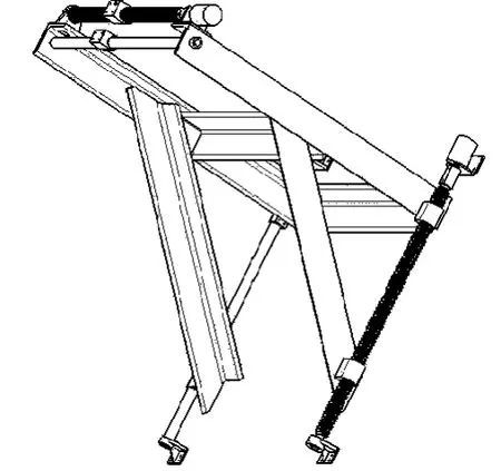
Fig.1 XY movement mechanical structure
The welding manipulator must quickly leave the weldment after arc striking,and the pneumatic transmission system has the advantages of rapid action,sensitive reaction,small resistance loss and leakage,and low cost,so the design adopts a cylinder as the rapid moving mechanism.Through the analysis and calculation,the design finally selects CDMU40F-16S-C73 type cylinder.The pneumatic arc striking mechanical structure of the welding torch is shown in Fig.2.
The design uses a photoelectric sensor to detect arcing success.By sensing the light intensity in the welding process in real time,the control system is to detect the need for re-arcing.
In addition,the welding manipulator comprises a wire feeder.It is the role of automatic supply welding wire during the welding process.This design uses the Panasonic 500 type wire feeding machine(SB-10-A-1).
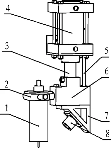
Fig.2 Pneumatic are striking mechanical structure of welding torch
Considering specific sizes of the hydraulic cylinder bottom in the design,through analysis and calculation,the machanical structure overall design of welding manipulator is finally accomplished.It is shown in Fig.3.
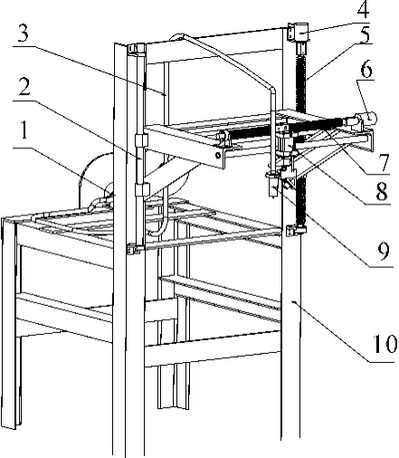
Fig.3 Overall machanical structure of welding manipulator
The welding torch and pneumatic cylinder in Fig.3 are fixed to the slider in X direction by bracket.The stepper motor in X direction drives ball bearing screw in X direction to rotate,drives slider to move in X direction,and then drives welding torch to move in horizontal linear direction eventually.The moving principle of welding torch in Y direction is the same as that in X direction.The welding torch moving in X direction is used to adjust the weld distance between the welding torch and the hydraulic cylinder.The welding torch moving in Y direction is used to adjust that the center of welding torch is aligned with the center of weld seam.NB-500 type wire feeder is fixed to the rear end of the trestle and feeds welding wire automatically through the wire conduit.
3.Design of pneumatic transmission system
The pneumatic transmission system is the key to the completion of the welding manipulator arcing action.Because arc striking uses spot contact method,it needs the welding torch contact the welding within a short time,and then rapidly seperate.The pneumatic transmission system diagram of manipulator is shown in Fig.4.
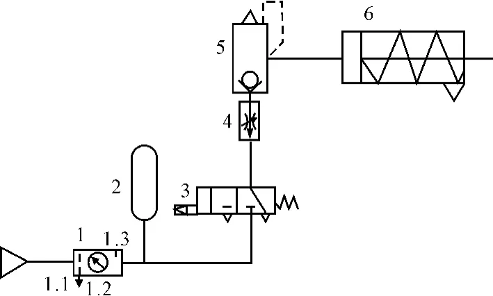
Fig.4 Pneumatic transmission system
According to the task requirements,through design calculation,the main pneumatic control circuit components are shown in Tab.1.
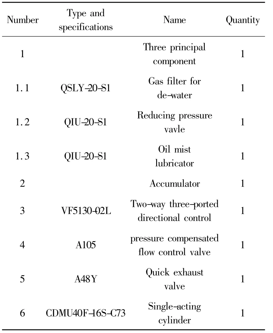
Tab.1 Type and specifications of the components
The design uses a quick exhaust device 5 which ensures that the pneumatic cylinder returns quickly.A pressure compensated flow control valve 4 is used to adjust the speed and the stablity of arc striking.Arc tank 2 is used to ensure instantaneous and large flow compressed air.These designs can guarantee the speed stability of pneumatic cylinder in welding arc striking process, and then avoid adverse effects.Through the quick exhaust device,the load of the single-acting cylinder spring is decreased when it return.Therefore,the return speed of pneumatic cylinder becomes faster,which ensures that the pneumatic cylinder reaches the limit switch position after the reset operation in a relatively short period of time.
4.Design of control system
The design adopts PLC control system.According to the analysis of manipulator control requirements,PLC is required to provide 9 input points and 14 output points.So,the manipulator uses Mitsubishi FX2N-48mr-001 PLC as the controller.The PLC main program flow chart is shown in Fig.5.
The control principle is that:
1)At beginning,the diameter and thickness of the to be welded hydraulic cylinder is input by the operator.The operator controls welding torch to move in X direction in order to make the welding torch at the weld seam center roughly.After that,the operator control the welding torch to move in Y direction in order to make the welding torch arrive at a suitable position.
2)After the hydraulic cylinder is fixed to the welding table,the complete signal is sent to the PLC for subsequent operations.
3)Manual selection.The operator determines whether it welds automatically.
4)After accomplishing the arc preparations,the solenoid operated directional valve is energized,that makes the pneumatic cylinder move.And then,the PLC control system sends signal to the stepper motor in Y direction in order to ensure the distance of 10~15 mm between the welding torch and the weld seam.The distance can ensure the arc cannot be extinguished.
5)Signal detection.Based on the measured light intensity signal by photo-electric sensor,it is judged that whether the arc striking is successful or not.If successful,the PLC control system continues with the following operation.Otherwise,the PLC sends the stepper motor a pulse signal in Y direction to make it reset and controls the NB-500 welding machine to arc strik again.
6)The position of the welding manipulator remains unchanged in the welding process,the state of NB-500 welding machine is keep,and the sensor detects the photo-electric signal in real time.If the case of accidental arc extinguishing appears,the PLC will send signals to control stepper motor to reset.And further,the welding torch will move up to 1 ~5 mm to ensure the welding torch and the weldment of the same distance.
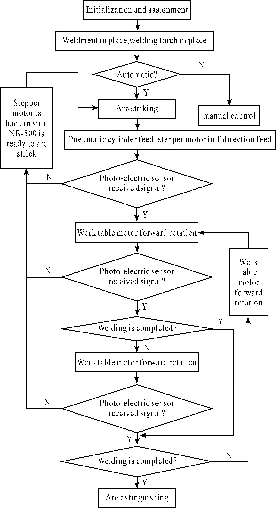
Fig.5 PLC main program flow chart
7)It is monitored in real time during welding that whether the welding is completed.The finished sign is the weldment rotating a circle or a few laps.
8)The arc extinguishing operation is required when the welding finished.The weldment stops rotating and the welding torch repeats arc striking and arc extinguishing several times.That is to ensure the final weld seam completes closure.
9)After getting finished signal,the PLC controls stepper motor is to reset and sends welding machine a stop signal.And system waits for the next weldment in place,and repeats all the operation above.
5.Conclusions
In modern industry,as the automated production and the demand of human security in job continues to be strengthened,manipulator is used more wildly.The welding manipulator has the advantages of simple in design,stable and reliable act,and research and development in low-cost.The PLC control system has the characteristic of simple in programming,high reliability,good in versatility,strong functions and easy to use.
[1] LV Juncheng,YANG Lianbo.Structural stability analysis on 4-dof simple welding manipulator[C]//Advanced Manufacturing Technology and Systems,2012.
[2] DONG Maoqi,YU Fusheng,WANG Xue.Design of control unit for 3-D manipulator based on S7-200 PLC[J].Chinese Hydraulics& Pneumatics,2010(8):4-5.
[3] WANG Xuanyin,DING Yuanming.Adaptive Real-time Predictive Compensation Control for 6-DOF Serial Arc Welding Manipulator[J].Chinese Journal of Mechanical Engineering,2010,23(3):361 -365.
[4] WANG Yueqin.Control System Design of the Manipulator Based on PLC[J].Chinese Hydraulics & Pneumatics,2011(9):41 -42.
[5] GUAN Ming,ZHOU Xilun,MA Lijing .Control System Design of Manipulator Based on PLC[J].Manufacturing Automation,2012,34(14):120 -121,142.
- 机床与液压的其它文章
- Experimental Study on Mechanical Properties of Low Carbon Steel with Ultrasonic Vibration Tensile
- Finite Element Analysis for a New Friction-based Limited-slip Differential Housing
- Precision Measurement of Series Motor Housing Based on CMM
- Wavelet Analysis Fault Information and Realization in Virtual Instrument
- Synchronous Motion Servo-control of Biaxial Cross Coupling Based on Intelligence Fusion Strategy
- Simulation and Optimization Analysis of Circuit Breaker Operating Mechanism

