Modeling and Simulation of Fourier Section Curves of Non-circular Gear and Study on Impact of Parameters
XU Gaohuan ,CHEN Jianneng
1.Zhejiang Water Conservancy and Hydropower College,Hangzhou 310018,China;
2.Zhejiang Sci-tech University,Hangzhou 310018,China
Special requirements of non-uniform transmission can be achieved by non-circular gear.Non-circular gear pair can be designed and manufactured precisely due to the requirements of movement.Motion accuracy is higher than other mechanical system,non-circular gear section curve can be unidirectional continuous rotation,variable motion is stable and periodic,gear structure is compact,transmission is smooth and it is easy to achieve balance[1 -3].The common non-circular gear is eccentric circle and oval gear.Both noncircular gear and pitch curve expression are simple,it is easy to design and manufacture,but the adjustment parameters are comparatively limited.
The eccentric circle gear is the spur gear’s center which is deviated from gear center.The eccentricity of two gears is the same,which composed of a pair of eccentric gear.In the initial position,the axis and the rotational center of the two gears in the straight line and the eccentric direction is consistent.The eccentric amount of this non-circular gear is the main parameter and the speed could be changed by adjusting this parameter.Meshing gap will change at its rotation cycle which will cause vibration and speed beating.Too much eccentric will cause detachment drive[4],which can’t be used to precisely drive,and the variable speed range of eccentric gear is limited and it is not conducive to further optimization.
Rotation center of oval gear is the focal point of the ellipse.The engagement point is in a straight line which through the center of rotation.The engagement of two gears in any position,neither separation will not be cut,smooth transmission,the transmission characteristics superior to eccentric circle gear.The parameters of oval gear pitch curve are the major and minor axis length and they could be changed to adjust the shape of pitch curve,the gear ratio and transmission characteristics[4].Since elliptical expression is difficult to precisely control the shape of the details of the location,the gear ratio of transmission with special requirements can’t be achieved.
Fourier noncircular gear transmission mechanism is proposed in this paper.This kind of gear has some advantages such as continuous drive,smooth movement and it could provide more adjustable parameters to easily optimize the mechanical properties[5].The transmission characteristics of the Fourier non-circular gear will be studied and a theoretical basis for the design of a new type of non-uniform transmission system will be provided in this paper.
1.The basic model of Fourier noncircular gear pitch curve
Mathematical model of the Fourier section curve could be expressed as follows:

Where,the parameters are:active non-circular gear polar radius r1,the pitch curve parameters a0、a1、b1、a2、b2,the active non-circular gear order n1and the active non-circular gear angular displacement φ1.
1.1.The diameter relationship of Fourier noncircular gear and center distance
Driven gear is conjugate non-circular gear of drive gear,meshing process must meet a necessary and sufficient condition:The closed condition of the non-circular gear is that the ratio of the rotation number of the two non-circular gear is N or/1/N(N is a positive integer).Take the value as 1,generally one rotation of the capstan and the driven gear is also just one rotation.The driven gear section curve could be expressed:

Where,a is the center distance of conjugate noncircular gears,r1(φ1)is the polar radius of active non-circular gear,r2(φ2)is the polar radius of the driven non-circular gear.
According to the engagement theory,the curve length of meshing gear transmission section has the following relationship:

The instantaneous angle Δφ1is the capstan in the angle φ1,the instantaneous rotation angle is Δφ2when the driven gear has the angle φ2.
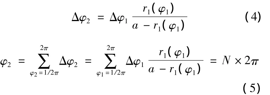
Δφ1、r1(φ1)can be obtained according to specific institutions,in order to ensure normal gear transmission,the center distance of a is obtained from this formula.
1.2.Transmission ratio of Fourier noncircular gear
According to the characteristics of the non-circular gear,two gear at any moment,there is a point where a relative speed is always equal to zero,which is located in the connection line of the two non-circular the gear rotates center,and meet the conditions that the meshing pitch curves are equal[1 - 3,6].Therefore,the transmission ratio is:
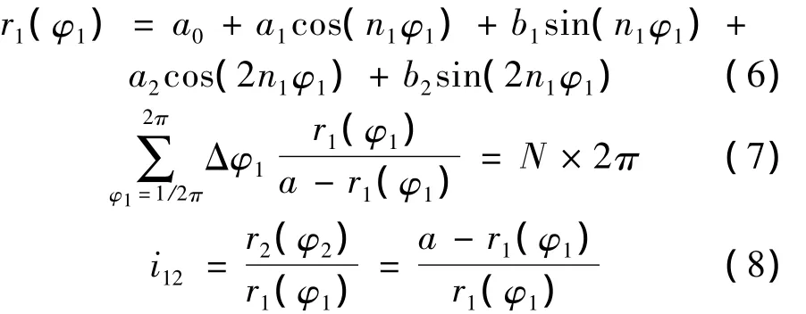
Then the speed N could be determined,a can be obtained and the transmission ratio can be determined according to the capstans section curve expression.It still complies with the basic gear meshing law:① non-circular gear pitch curve is closed;②The perimeter of the pitch curve is l=πmz,m is the modulus,z is the number of teeth.
2.Meshing simulation of Fourier noncircular gear
2.1.Meshing simulation of Fourier noncircular gear pitch curve
According to the engagement theory of the Fourier noncircular gear,we adopt MATLAB software to analyze the impact of various parameters on the transmission characteristics.
The parameters of the initial value are as follows:

The Fourier section curve is expressed as:

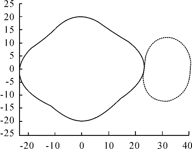
Fig.1 the simulation of Fourier noncircular gear pitch curve
2.2.The impact of the parameters on the shape of the curve and the transmission ratio
If one parameter is changed and the other keep the same,the results are shown as follows:
As shown in Fig.2(a),with a0increasing,the pitch curve become bigger,the center distance increases and the contour gear pair increases;center distance equal increments along with a0,i.e.each additional 5 mm,center distance increases 15 mm,there are equidistant lines between the driven gear rotation centers.
Fig.2(b)shows,with a0increasing,the transmission ratio curves become gently,two peaks is gradually reduced,maximum value is reduced,the minimum of transmission ratio is gradually increased,the average value is gradually reduced.
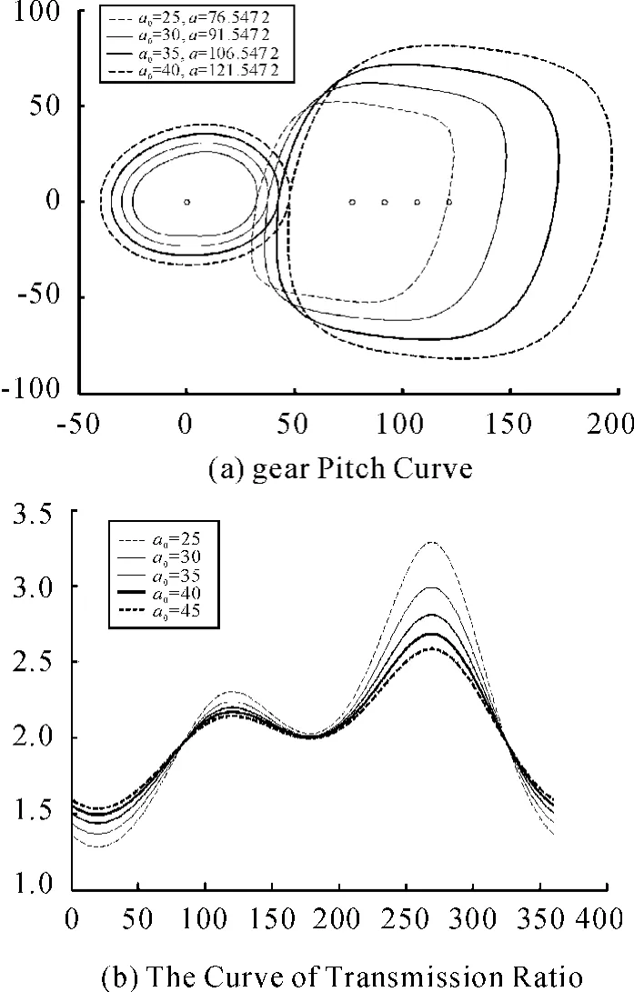
Fig.2 The impact of the parameter a0on the shape of the gear pitch curve and the transmission ratio
As shown in Fig.3(a),with a1increasing,the follower gear section curve gradually becomes high and narrow,drive gear gradually plump and moving right,the center distance increases slowly.
Fig.3(b)shown,with a1increasing,the curves between peaks of transmission ratio are gradually gentle.The curve maximum changed litter,the slope of outside the two peaks increased.The minimum of transmission ratio is gradually decreased.The average variation is small.Five curves go through two points with equal values.
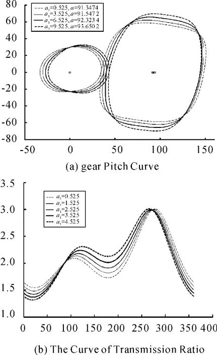
Fig.3 The impact of the parameter a1on the shape of the gear pitch curve and the transmission ratio
As shown in Fig.4(a),with a2increasing,the gear pair does not occur movement along the X-axis direction and the Y-axis direction.The capstan in the Y-axis direction becomes gradually flat and appears concave phenomenon.The driven gear becomes tactless and appears recessed phenomenon,the center distance increasing slowly.
As shown in Fig.4(b),with a2is increasing,the slope of the two peaks and the troughs of the transmission ratio are increased gradually.The maximum are gradually increasing generally and the minimum is gradually reduced.The average transmission increased slowly.
As Fig.5(a)shows,with b1increasing,the gear pair is not obvious movement along the X-axis direction,but the capstan gradually shift along the Y axis,and appears concave phenomenon,the driven gear around its center of rotation becomes dextral and sharp,and appears concave phenomenon.The center distance is slowly increasing.
As shown in Fig.5(b),with b1increasing,the gentle of transmission ratio curve is getting worse,the gap between the two-peaks gradually is increasing,maximum is gradually increased,and the minimum value is gradually reduced.The average transmission ratio is slowly increasing.The transmission ratio of the starting and ending points of the curve intersect at one point.Five curves are crossing into three points with equal values.
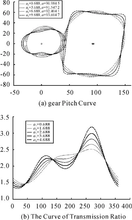
Fig.4 The impact of the parameter a2on the shape of the gear pitch curve and the transmission ratio
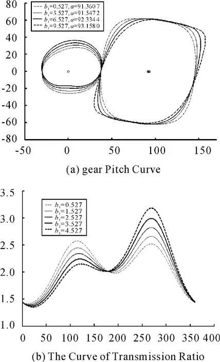
Fig.5 The impact of the parameter b1on the shape of the gear pitch curve and the transmission ratio
As shown in Fig.6(a),with b2increasing,gear pair did not occur the movement along the X-axis direction and the Y-axis direction,the driving gear and the driven gear occur angular displacement around the respective center,the driving gear gradually becomes flat,and appear concave phenomenon,the driven gear become tactless and appear recessed phenomenon,the center distance increasing slowly.
As the Fig.6(b)shows,with b2increasing,the slope of the two peaks and the troughs of the transmission ratio are increased gradually.The maximum are gradually increasing generally and the minimum is gradually reduced.The average transmission increased slowly.Curves of transmission ratio are intersected at one point.Five curves are crossing into three points with equal values.
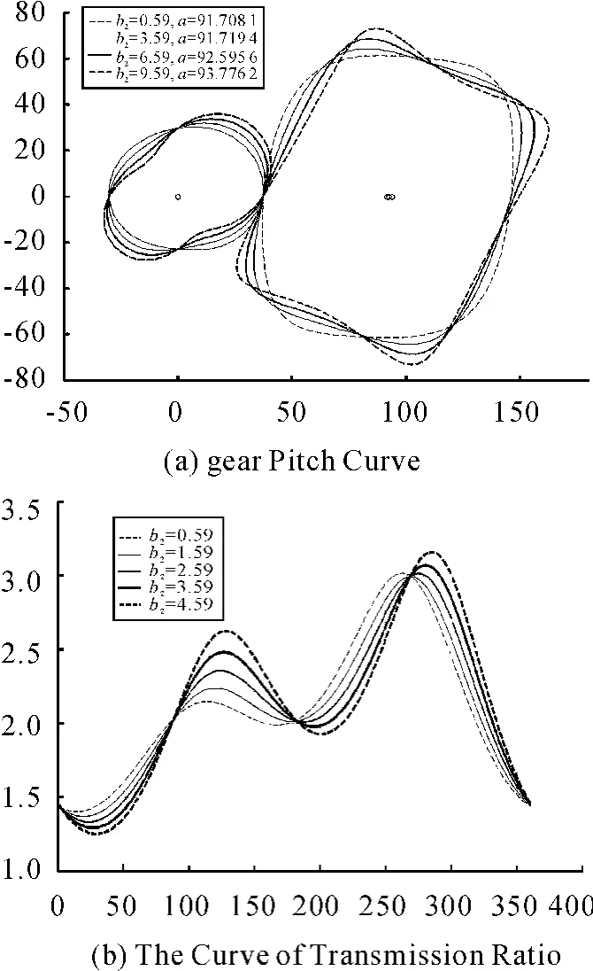
Fig.6 The impact of the parameter b2on the shape of the gear pitch curve and the transmission ratio
3.Conclusions
1)Cycle continuity.Cycle of the polar coordinates function of the noncircular gear pitch curve is 2π,and the function is continuous smooth.Fourier functions are composed of the two functions sin(x)and cos(x).Each of them is 2π periodic and an norder derivable function.Therefore,it has good continuous smoothness when Fourier function fits with noncircular gear pitch curve.
2)It is flexible and easy to adjust the shape of the curve.The gear pitch curve of elliptical gears are typical mathematical models.Curve flexibility is poor,parameter adjustment is difficult to meet agency requirements.Fourier pitch curve have more adjustment parameters(coefficient of order,phase,etc.).It is easy to change the shape of the curve.
[1] WU Xutang.Noncircular gear and non-uniform transmission[M].Beijing:Machinery Industry Press,1997.
[2] Shinn-Liang Ch,Chug-Bian T.Mathematical model and undercutting analysis of elliptical gears generated by rack cutters[J].Mech Mach Thory,1996,31(7):879 -890.
[3] ZHANG Rui,ZAO Fengxia,WU Xutang.Study on the Design Method of a New-style Sinusoidal Noncircular Gear[J].MACHINE DESIGN & RESEARCH,2010,26(4):71-74.
[4] ZHAO Yun.Agricultural machinery analysis and synthesis[M].Beijing:China Machine Press,2008.
[5] LI Ge,LI Hui,YANG Aiqian,et al.Kinematic analysis on Fourier curve non-circular gears transplanting mechanism[J].CSAE,2011,27(8):126 -131.
[6] WU Xutang,WANG Haigui.Non-circular Gear and Nonuniform Drive[M].Beijing:Mechanical Industry Press,1996:105-106.
- 机床与液压的其它文章
- Experimental Study on Mechanical Properties of Low Carbon Steel with Ultrasonic Vibration Tensile
- Finite Element Analysis for a New Friction-based Limited-slip Differential Housing
- Precision Measurement of Series Motor Housing Based on CMM
- Wavelet Analysis Fault Information and Realization in Virtual Instrument
- Synchronous Motion Servo-control of Biaxial Cross Coupling Based on Intelligence Fusion Strategy
- Simulation and Optimization Analysis of Circuit Breaker Operating Mechanism

