厚度可控薄板形Silicalite-1的制备
姚小强 徐向宇 吕 志 焦 琨 宋家庆,* 李兆飞王 骞 阎立军 何鸣元
(1北京化工大学,化工资源有效利用国家重点实验室,北京100029;2中石油石油化工研究院,北京100915;3华东师范大学,上海市绿色化学与化工过程绿色化重点实验室,上海200062)
1 Introduction
ZSM-5 material was first synthesized by Mobil Company in 1972.1Soon after that,its crystal structure was determined as MFI-type framework with unique pore structure,which cross from the straight and sinusoidal channels with the aperture sizes of 0.51-0.56 nm and 0.54-0.56 nm along the b and a axes,respectively.2It has been increasingly widely used in industrial processes such as aromatization,isomerization,alkylation,due to its distinctive pore structure,thermal/hydrothermal stability,high solid acidity,excellent shape selectivity.3The catalytic and sorption properties of the zeolite are seriously influenced by their crystal size and morphologies.4Specifically for MFI-type zeolite,since the reactive molecules mainly enter the crystals by the straight channels,it is of great importance to reduce the straight channel along the b axis to improve the diffusion of molecules for the catalytic reactions.5
More and more researchers pay attention to the synthesis of the ZSM-5 with various methods.6-8An important breakthrough is that F-is replaced of OH-as mineralizer in zeolite synthesis,9which allows us to synthesize ZSM-5 in the neutral or acidic conditions and extend synthetic pathway of the ZSM-5.10In recent decades,a lot of modifications on the morphologies of MFI-type zeolite had been done to adapt to various industrial demand.11,12Tong et al.13prepared cylindrical ZSM-5 by using sodium silicate as silica source and ethylamine as template.It is confirmed that the starting materials and synthesized conditions are the most significant factors to determine the particle size and crystal morphology,14-16while the additives also play a prominent role in directing their particle size and morphology.For example,Bonilla et al.17explored the effect of structure-directing agents(SDA)on the particle morphologies.They successfully controlled over relative crystal growth rates along the three main crystallographic axes by using dimers and trimers of tetrapropylammonium hydroxide as SDA of ZSM-5 and got pill-shaped and leaf-shaped crystals.Arichi and Louis18reported that they synthesized ZSM-5 in the neutral condition when fluoride ion as mineralizer.The morphology of ZSM-5 is coffin-shaped when size of the crystals along the b axis is about 4 μm.The main difference of the coffin-shaped morphology and plate like morphology is that molecular sieve along b axis of coffin-shaped morphology is thicker,and usually greater than 1 μm instead of the thickness of the sheet-shaped in nanoscale.Zhang and Jin19prepared ZSM-5 with coffin-shaped morphology,with its size about 3 μm in a nonionic emulsion system containing polyoxyethylated alkylphenol surfactants.Lin and Yates20also reported the synthesis of coffin-shaped Silicalite-1 in microemulsion system composed of surfactant cetyltrimethylammonium bromide(CTAB)and butanol.The size range was 20-100 μm in length and 2-10 μm in thickness.Lee et al.21successfully synthesized nano plate like Silicalite-1 with 40 nm in thickness.It was also prepared in anionic microemulsions when tetraethylorthosilicate(TEOS)as silica source.While the all-Si MFI zeolite,i.e.,Silicalite-1,also has potential applications due to its high stability and hydrophobic properties,22-25yet the controlled synthesis of the Silicalite-1 with various morphologies was rarely reported.Especially for the layered materials,the thickness along the b axis was rather large in the aforementioned references.And organic surfactants were often used to decrease the thickness.So we carried out our synthesis with careful tuning of the synthetic parameters aiming to prepare silicalite-1 zeolite with controlled thickness along b axis with industrial raw materials and no surfactant.
2 Experimental
2.1 Synthesis
In this study,a homemade silica gel prepared by the hydrolysis of TEOS was selected as the silicon source.First TEOS(assay)from Beijing Chemical Works,ethanol(assay)from Beijing Chemical Works,deionized water and NH4F(assay)from Beijing Chemical Works was mixed with the molar ratio of 6:1:4:0.01 and then the mixture was vigorously stirred for 0.5 h.The resulting gel was at 60°C aged for 2 days and dried at 160°C for 2 days,and then the silica gel was dried and grinded into 40-200 mesh silica particles followed by a calcination process at 800°C for 2 h in muffle furnace.
The initial gel for the crystallization of Silicalite-1 samples were prepared by mixing the homemade silica gel(SiO2),tetrapropylammonium hydroxide(TPAOH,21%(w))from Tokyo Chemical Industry Co.,Ltd.,ammonium fluoride(assay)from Beijing Chemical Works and deionized water with the molar ratio of 1.0SiO2:0.2TPAOH:25H2O:xNH4F(x=0-0.8)as listed in Table 1.Then,the mixture was stirred for about 30 min to get a uniform slurry.The pH of the slurry was measured by pH meter(PB-10 pH meter)from Germany through pH glass electrode into the solution,and the final results are shown in Table 1.Following that,the slurry was transferred into a Tef l on-lined stainless autoclave and kept at 170°C for 1 day.And then the product was filtered and washed with H2O followed by drying at 393 K overnight in air.Finally the samples were calcined at 550°C for 5 h in order to remove the SDA.
2.2 Characterizations
Powder X-ray diffraction was conducted on a Bruker D8 Advance diffractometer with Cu Kαradiation.All the diffractiondata were collected in the range of 5°and 50°with continuous scanning mode.
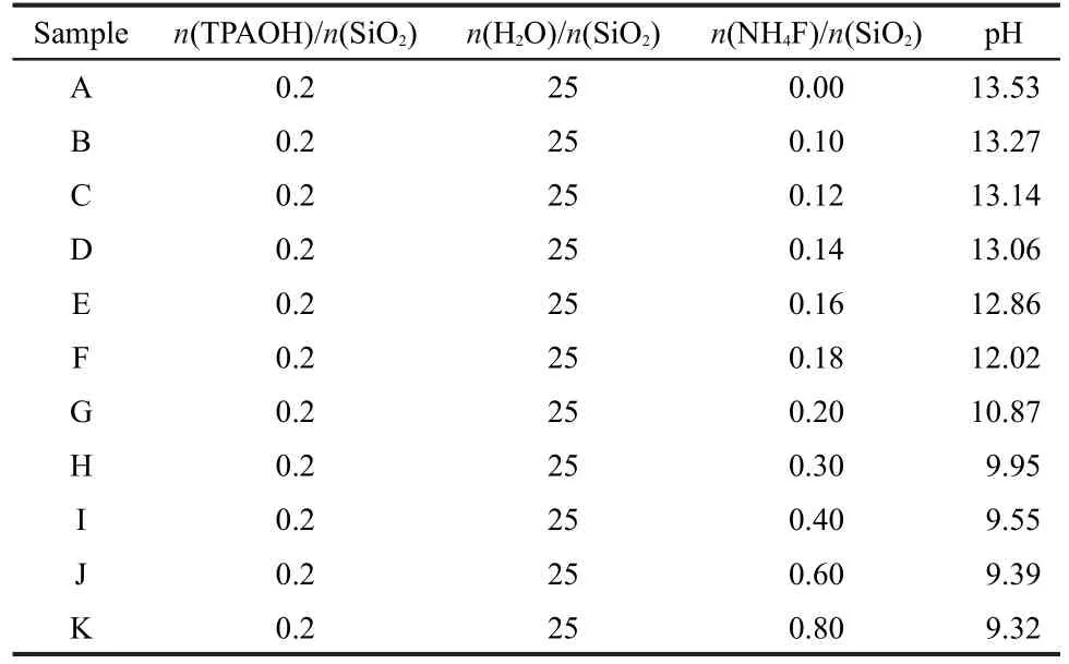
Table 1 Chemical compositions and pH values of the initial gel of all the samples
Scanning electron microscope(SEM)images were taken with a Zeiss Supra 55 and its acceleration voltage was set to be 3 kV.High resolution transmission electron microscopy(HRTEM)studies were performed on a JEOL JEM-2200 with an acceleration voltage of 200 kV.
3 Results and discussion
In this study,fluoride ion(F-)was used as the mineralizer instead of the conventionally used hydroxide ion.It offered an opportunity to explore the synthesis and morphology studies of Silicalite-1 at near neutral conditions.For instance,the pH value of the initial gel decreased from 13.53 to 9.32 with the increase of NH4F/SiO2molar ratio from 0 to 0.8 as summarized in Table 1.Also,it is noted that all the other parameters in the synthesis were kept constant except the concentration of NH4F and corresponding pH values in this study.
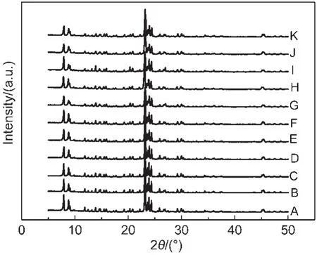
Fig.1 XRD patterns of as-synthesized Silicalite-1 samples
Fig.1 displayed the X-ray diffraction patterns of the as-synthesized samples,which clearly showed that we have gotten the pure MFI structure with the SDA molecules inside the framework.In addition,it also implied that the MFI-structure could be easily prepared in a very wide NH4F/SiO2molar ratio and wide pH value range.
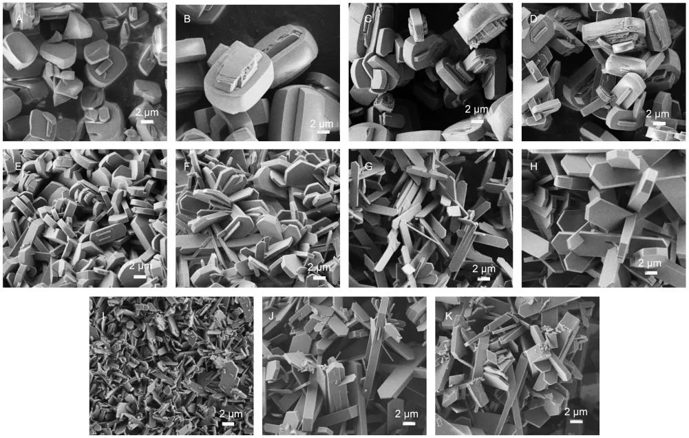
Fig.2 SEM images of as-synthesized Silicalite-1 samples
As is well known that the morphology of the zeolite particles may play an important role in the catalytic reactions,the SEM technique was applied to study the morphologies of them.Fig.2 shows the morphologies of all those samples with the same magnification.For the sample prepared without NH4F(Fig.2A)in the initial gel,the particles were rather irregular and had aggregations to some extent.With the increase of NH4F amount(Fig.2B to Fig.2E,NH4F/SiO2molar ratio from 0.10 to 0.16),the highly dispersed ellipse-shaped particles with intergrowth were gotten,and their mean particle dimensions was about 3 μm.When the NH4F/SiO2molar ratio reached 0.18 and the pH value was smaller than 12.02 in the initial gel,plate like morphology emerged.This plate like morphology was kept with the further increase of NH4F/SiO2molar ratio,yet it is noteworthy that the increase of the concentration of NH4F gel had a considerable influence on the plate thickness.For example,the mean particle thickness is about 700 nm when n(NH4F)/n(SiO2)=0.18(Fig.2F),and it decreased to 200 nm when NH4F/SiO2molar ratio reached 0.4(Fig.2I).However,the further increase of the NH4F/SiO2molar ratio did not decrease the thickness of the plates.As shown in Fig.2J and Fig.2K,the plates became not uniform and there existed plates with thickness of more than 2 micron.It is induced that the concentration of F-and H+(pH value)co-directed the morphologies of the particles.When the F-concentration was very low,the pH value had a predominant effect on the morphologies of the particles.When the NH4F concentration increased to a certain value,then F-would be more important in directing the morphology.So some particles with 2 micron or even larger size would formed when the n(NH4F)/n(SiO2)>0.6 since the existed F-acted as a good mineralizer.
So,it is concluded that the plate like Silicalite-1 with controllable thickness could be achieved in the synthesis.Considering that in the MFI structure,the straight channel is along the b axis and the zigzag channel is perpendicular to b axis.So for a plate like Silicalite-1 particle,one would hope that the plate was perpendicular to the b axis so that the molecules would have better accessibility to this direct channel.
To confirm the pore orientation,a calcined Siliclite-1 sample(sample G)was studied by the HRTEM technique.Fig.3 shows the HRTEM image taking on the edge of our plate particle perpendicular to the plate.A Fourier transformation(FT)was done according to this image as shown in the insert of Fig.3.According to this Fourier transformed pattern,we could easily conclude that this direction should not be along[001].26But so far it is difficult to judge whether it is along the[010]or[100]direction,i.e.,along the b or a axis.Then a structure model taken from the IZA website was used to simulate the kinematic electron diffraction pattern as shown in Fig.4.Now it is clear that our FT pattern is similar to the simulated pattern along[010]and the appearance of absent reflections is due to the dynamical effects.So it is proved that in our materials,the straight channel perpendicular to the plate is along the b axis.

Fig.3 HRTEM image of sample G in the[010]zone and the FT pattern shown as an insert
All the samples were calcined at 550°C for 4 h to remove the organic template,and then they were heated at 800,1000,and 1100°C for 0.5 h to study their thermal stability.Fig.5 shows the XRD patterns of sample G treated at different temperatures and the XRD pattern of the as synthesized sample is also included for comparison.It is clearly seen that the patterns of the sample after heat treatment were very similar to each other,which showed that this plate like Silicalite-1 sample was robust against the thermal treatment.In addition,Fig.6 shows the morphologies of sample G and its high temperature treated samples.It is seen that there is almost no change in their morphologies.And the particles are still highly dispersed without any aggregation even after treated at a very high temperature.The morphology studies further confirmed that this material had very good thermal stability.In addition,we have carried out the thermal treatments for other samples synthesized with different NH4F/SiO2molar ratio and found that all these plate like Silicalite-1 materials had good thermal stability regardless of the plate thickness.This feature of the plate like MFI materials might make them very promising in real applications.Currently,we are carrying out the catalytic studies of the Al-doped plate like samples as well as the crystal growth mechanism.
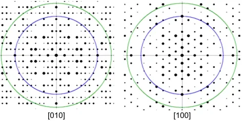
Fig.4 Simulated electron diffraction patterns of MFI structure along[010]and[100]directions
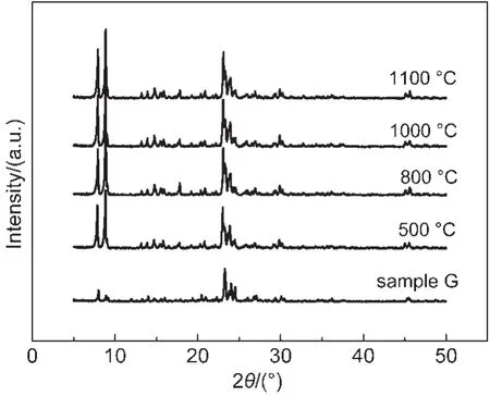
Fig.5 XRD patterns of synthesized sample G and sample G calcined at different temperatures
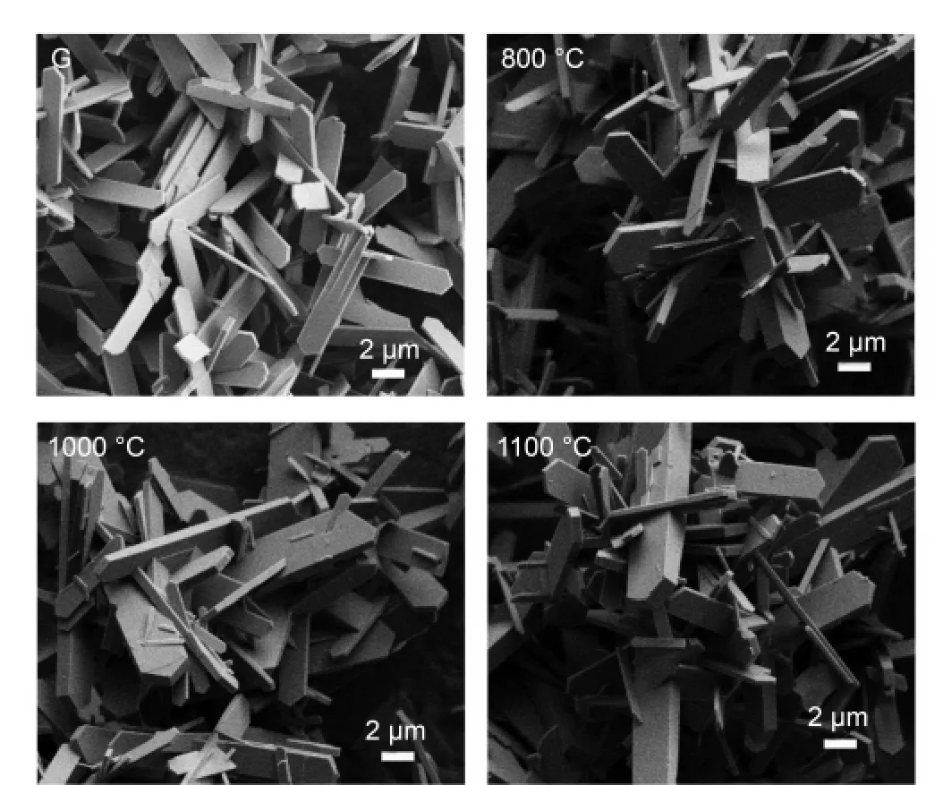
Fig.6 SEM images of sample G and sample G calcined at different temperatures
4 Conclusions
In this study,it was found that the plate like Silicalite-1 materials could be successfully achieved and the plate thickness could be controlled by simply introducing some amount of NH4F into the initial gel.HRTEM studies confirmed that the plate was perpendicular to the b axis.In addition,this plate like morphology was rather robust against high temperature.These materials might have potential applications with the controlled lengths along the b axis and good thermal stability since it could accelerate the diffusion of the guest molecules significantly.Moreover,this facile approach might be expanded to the synthesis of other zeolite materials with desirable morphologies.
(1)Argauer,R.J.;Landolt,G.R.Crystalline Zeolite ZSM-5 and Method of Preparing the Same Zeolites.US Patent 3702886,1972-11-14.
(2) Olson,D.H.;Kokotailo,G.T.;Lawton,S.L.J.Phys.Chem.1981,85,2238.doi:10.1021/j150615a020
(3)Zhao,X.B.;Guo,X.W.;Wang,X.S.Energy Fuels 2006,20,1388.doi:10.1021/ef060004a
(4) Reddy,J.K.;Motokura,K.;Koyama,T.;Miyaji,A.;Baba,T.J.Catal.2012,289,53.doi:10.1016/j.jcat.2012.01.014
(5)Wang Z.X.;Yan,W.F.;Tian,D.Y.;Cao,X.J.;Yu,J.H.;Xu,R.R.Acta Phys.-Chim.Sin.2010,26,2044.[王周翔,闫文付,田大勇,曹学静,于吉红,徐如人.物理化学学报,2010,26,2044.]doi:10.3866/PKU.WHXB20100714
(6)Wang,L.G.;Sang,S.Y.;Meng,S.H.;Zhang,Y.;Yue,Q.;Liu,Z.M.Mater.Lett.2007,61,1675.doi:10.1016/j.matlet.2006.07.097
(7)Chen,X.X.;Yan,W.F.;Cao,X.J.;Xu,R.R.Microporous Mesoporous Mat.2010,131,45.doi:10.1016/j.micromeso.2009.11.039
(8)Karimi,R.;Bayati,B.;Aghdam,N.C.;Ejtemaee,M.;Babaluo,A.A.Powder Technol.2012,229,229.doi:10.1016/j.powtec.2012.06.037
(9) Barrer,R.M.J.Chem.Soc.1948,127,2158.
(10) Guth,J.L.;Kessler,H.;Higel,J.M.;Lamblin,J.M.;Patarin,J.;Seive,A.;Chezeau,J.M.;Wey,R.Zeolite Synthesis in the Presence of Fluoride Ions.In Zeolite Synthesis;Occelli,M.,Robson,H.E.Eds;ACS Symposium Series;American Chemical Society:Washington,DC,1989;pp 176-195.
(11)Yao,M.;Hu,S.;Wang,J.;Dou,T.;Wu,Y.P.Acta Phys.-Chim.Sin.2012,28,2122.[姚 敏,胡 思,王 俭,窦 涛,伍永平.物理化学学报,2012,28,2122.]doi:10.3866/PKU.WHXB201206211
(12)Ni,Y.M.;Sun,A.M.;Wu,X.L.Microporous Mesoporous Mat.2011,143,435.doi:10.1016/j.micromeso.2011.03.029
(13)Tong,W.Y.;Kong,D.J.;Liu,Z.C.;Guo,Y.L.;Fang,D,Y.Chinese Journal of Catalysis 2008,12,1247. [童伟益,孔德金,刘志成,郭杨龙,房鼎业.催化学报,2008,12,1247.]
(14)Mintova,S.;Valtchev,V.Microporous Mesoporous Mat.2002,55,171.doi:10.1016/S1387-1811(02)00401-8
(15) Feng,H.;Chen,Y.;Li,C.;Shan,H.Journal of Fuel Chemistry and Technology 2008,36,144.doi:10.1016/S1872-5813(08)60015-8
(16)Sang,S.Y.;Chang,F.X.;Liu,Z.M.;He,C.Q.;He,Y.L.;Xu,L.Catal.Today 2004,93,729.
(17) Bonilla,G.;Diaz,I.;Tsapatsis,M.;Jeong,H.K.;Lee,Y.;Vlachos,D.G.Chem.Mater.2004,16,5697.doi:10.1021/cm048854w
(18)Arichi,J.;Louis,B.Cryst Growth Des.2008,11,3999.
(19) Zhang,Y.;Jin,C.J.Solid State Chem.2011,184,1.doi:10.1016/j.jssc.2010.10.012
(20) Lin,J.C.;Yates,M.Z.Langmuir 2005,21,2117.doi:10.1021/la0473456
(21) Lee,S.;Carr,C.S.;Shantz,D.F.Langmuir 2005,21,12031.doi:10.1021/la052181u
(22)Yeong,Y.F.;Abdullah,A.Z.;Ahmad,A.L.;Bhatia,S.Chem.Eng.Sci.2011,66,897.doi:10.1016/j.ces.2010.11.035
(23) den Exter,M.J.;van Bekkum,H.;Rijn,C.J.M.;Kapteijn,F.;Moulijn,J.A.;Schellevis,H.;Beenakker,C.I.N.Zeolites 1997,19,13.doi:10.1016/S0144-2449(97)00044-4
(24) Serrano,D.P.;Calleja,G.;Botas,J.A.;Gutierrez,F.J.Sep.Purif.Technol.2007,54,1.doi:10.1016/j.seppur.2006.08.013
(25) Ramachandran,C.E.;Chempath,S.;Broadbelt,L.J.;Snurr,R.Q.Microporous Mesoporous Mat.2006,90,293.doi:10.1016/j.micromeso.2005.10.021
(26) Hovmöller,S.Ultramicroscopy 1992,41,121.doi:10.1016/0304-3991(92)90102-P

