Effects of Temperature Gradient and Cooling Rate on the Formation of Methane Hydrates in Coarse Sand
Wang Yingmei; Wu Qingbai; Zhang Peng; Jiang Guanli
(1.State Key Laboratory of Frozen Soil Engineering, Cold and Arid Regions Environment and Engineering Research Institute, Chinese Academy of Sciences, Lanzhou 73000; 2. Western China Energy & Environment Research Center, Lanzhou University of Technology, Lanzhou 730050)
Effects of Temperature Gradient and Cooling Rate on the Formation of Methane Hydrates in Coarse Sand
Wang Yingmei1,2; Wu Qingbai1; Zhang Peng1; Jiang Guanli1
(1.State Key Laboratory of Frozen Soil Engineering, Cold and Arid Regions Environment and Engineering Research Institute, Chinese Academy of Sciences, Lanzhou 73000; 2. Western China Energy & Environment Research Center, Lanzhou University of Technology, Lanzhou 730050)
Temperature gradient and cooling rate have an obvious effect on formation of methane hydrate. The process for formation of methane hydrate in coarse sand is monitored to understand the relationship between temperature gradient and cooling rate and nucleation, growth and distribution of methane hydrate by using the electrical resistivity method. The results show that the change of resistivity can better reflect the nucleation and growth and distribution of methane hydrate. Temperature gradient promotes the nucleation, formation, and formation rate of methane hydrate. At a temperature gradient of 0.11 ℃/cm, the rate of methane hydrate formation and saturation reaches a maximum. Cooling rate has little effect on the methane hydrate formation process. Judging from the outcome of final spatial distribution of methane hydrate, the cooling rate has an obvious but irregular effect in coarse sand. The effect of temperature gradient on distribution of methane hydrate in coarse sand is less than that of cooling rate. At a temperature gradient of 0.07 ℃/cm, methane hydrate is distributed uniformly in the sample. If the temperature gradient is higher or lower than this value, the hydrate is enriched in the upper layer of sample.
methane hydrate; cooling rate; temperature gradient; resistivity; formation; hydrate distribution
1 Introduction
Natural gas hydrates are solid, non-stoichiometric compounds consisting of small gas molecules and water[1]. The majority of gas hydrates in the natural environment is methane hydrates, which occur in permafrost regions and marine sediments[2]. A large number of experimental studies have been conducted on the formation and decomposition of gas hydrates. In recent years simulation studies have also been performed on associated processes on the formation of favorable environmental conditions. Makagon, et al.[3]simulated the formation process of gas hydrate in a porous medium and indicated that the pressure/temperature conditions shift to a higher pressure and a lower temperature region during the formation process. Bower, et al.[4]found that gas hydrates could be formed more easily in coarse sediments than in fine-grained sediments. Chuvilia, et al.[5]studied the effects of different types of clay on gas hydrate formation in quartz sand, and the results showed that gas hydrate stability is improved by the addition of an appropriate amount of clay. Smith, et al.[6]established a phase diagram for gas hydrates in porous media and provided the stable pressure and temperature data of methane hydrates in mesoporous media with different pore sizes. Zhao, et al.[7]investigated the formation and decomposition of gas hydrates in porous media through the measurement of impedance by using the multi-electrode method. Fan, et al.[8]studied the effects of salinity on the formation of gas hydrates in porous media. Chen, et al.[9]formed gas hydrates by using a natural seawater–methane system and analyzed the effects of temperature, pressure changes, and vibration and filtration patterns on the experimental results of gas hydrate formation. Liu, et al.[10]formed gas hydrates in seamud quartz sand and described the layered accumulation of gas hydrates in the sediment. Wu, et al.[11]studied the formation of methane hydrates in frozen coarse sand using computerized tomography technology. Jiang, et al.[12]and Zhang, et al.[13]examined the effect of cooling rate on methane hydrate formation in porous media and found outthat the cooling rate could significantly affect the hydrate nucleation and gas transformation rate. These findings are of practical significance in the exploration and evaluation of gas hydrates in porous media in permafrost regions.
The major factors that influence the formation of gas hydrates in permafrost regions are geothermal gradient, gas composition, pore fluid salinity, and pore pressure. Geothermal gradient and gas composition are the most signif icant among the factors because they determine the temperature and pressure conditions of gas hydrates during the formation process as well as the reserves[14]. Past geological survey of methane hydrate and present study show that there are close relationships between soil properties and characteristics of gas hydrate, such as the occurrence, saturation of hydrate. Generally, gas hydrate saturation is higher in the coarse sand than in the fine sand[15-17]. Obtaining samples of natural gas hydrates is difficult. Thus, simulations under permafrost environmental conditions and experimental studies on gas hydrate formation in sediments are extremely important. A number of methods have been developed for monitoring gas hydrates in experimental studies. The electrical resistivity method can be used to study the kinetics of formation and dissociation of gas hydrates in sediments for calculating hydrate saturation[18]. Hyndman, et al.[19]found that the resistivity of hydrate-containing sediments is significantly higher than that of non-hydrate-containing sediments. Zatsepina and Buffett[20-21]and Spangenberg, et al.[22]demonstrated that the level of resistivity reflects the scale of gas hydrate nucleation and the level of hydrate saturation. The morphology of gas hydrates in sediments determines the basic physical properties of hydrate-containing sediments and affects the results of hydrate saturation calculations[23].
To understand the effects of environmental conditions on the formation and distribution of gas hydrates in sediments, we monitored the formation process and distribution of methane hydrate in coarse sand under different temperature gradients and cooling rates by using the electrical resistivity method. Test results were used to evaluate the effect of temperature gradients and cooling rates on the formation and distribution of methane hydrate.
2 Experimental
2.1 Experimental apparatus
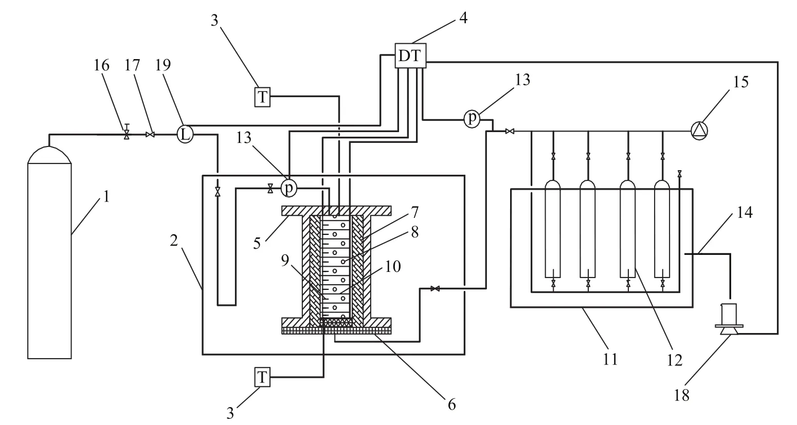
Figure 1 Schematic of the experimental apparatus
The experimental apparatus (Figure 1) included a resistivity and temperature monitoring system, an environmental control cooling bath system, a natural gas inlet pressure system, a gas decomposition and collection system, and a data collection and analysis system. The reactor consisted of a double-layered structure, including an outer stainless steel pressure barrel and an inner insulation barrel (1419 mL in volume, with a maximum pressure of 10 MPa). The accuracy of the pressure control was ± 0.01 MPa.Given the large size of the reactor, an 8 cm thick insulation barrel was used to prevent external interference on the ambient temperature. The temperature of the cooling bath was maintained between -100 ℃ and 250 ℃ with an accuracy of ± 0.1 ℃. The temperature of the reactor was controlled on both sides by the cooling bath to realize a pre-set temperature gradient. The reactor was placed in the insulation barrel connected to a thermostat (with an accuracy of ± 0.05 ℃). A total of 11 whole area electrodes, with a diameter of 7.9 cm and an interval between 1.3 cm and 2.7 cm, were arranged in the reactor. Two 0.5 mm thick copper sheets were used as the electrode plates, with polyurethane serving as the intermediate insulation. The electrode plate consisted of 45 holes (1 mm in diameter) for water circulation. In addition, 11 thermistors (insulated with the electrodes) were set on the electrode plate (with a test range of between -20 ℃ and 30 ℃, and an accuracy of ± 0.05 ℃). Data were collected by using the Datataker 80 (manufactured by Thermo Fisher Scientific Inc. in Australia; with a maximum resistance of<10 kΩ), in which a relay multiplexer was employed to assist in the isolation of the input in the internal vessel. When one channel was energized for measurement, the other channels were unaffected, thus verifying the accuracy of the data acquisition instrument for measuring soil resistance. Considering that the resistance measurement readings were relatively high, a 10 kΩ standard resistor was placed parallel on each channel. Data were collected through every 2 min.
2.2 Experimental design
The experiment was conducted using 0.5 mm to 1 mm grain-sized coarse sand as the porous media. The basic physical parameters and experimental conditions of the porous media are listed in Table 1. Prior to the reaction, a specific amount of sand soil was repeatedly washed with distilled water, dried at 105 ℃ for 24 h, and homogenized with distilled water. Wet sand together with 11 electrode sheets and 11 thermistors were placed into the reactor layer by layer. The resistivity and temperature of the 10 layers of sand soil were measured from top to bottom. After the samples were loaded, the collected resistivity and temperature data were verified. Thereafter, the reactor was evacuated for 30 min, and the temperature was maintained at 13 ℃ for the upper and lower cooling baths as well as the insulation barrel. Methane gas was slowly introduced in the reactor, and the pressure was stabilized at 9 MPa for 4 h (with the theoretical equilibrium temperature equating to 11.981 ℃). The temperatures of the top and bottom cooling baths were adjusted by using the pre-set cooling rate (at 2, 4, and 8 ℃/h, respectively). The temperature gradient is defined as the ratio of the difference between the temperatures of the bottom and top cooling baths and the height of the reactor. The temperature of the incubator was adjusted to the temperature median of the upper and lower cooling bath, thus allowing the methane hydrates to form in the sand soil. When the pressure reduction rate of the system became less than 0.01 MPa/h, the hydrate formation was considered to be completed. The reaction system was subsequently allowed to stabilize for a certain period. It took about 50 h to perform the hydrate formation reaction. Thereafter, the methane hydrate dissociation was conducted according to specific experimental requirements. The reaction system was allowed to stabilize for 24 h. The hydrate formation experiment was then conducted under different temperature conditions with the same experimental procedure.

Table 1 Physical parameters and experimental conditions of porous media
3 Results and Discussion
3.1 Changes in resistivity during hydrate formation
Figure 2 shows the process of changes in the temperature and pressure in the first nucleation layer and the relationships between temperature, resistivity, and gas consumption during the formation of methane hydrate. The temperature gradient in this experiment was set at 0 ℃/cm, the initial pressure at 7.51 MPa, and the cooling rate at 4 ℃/h. In Figure 2a, the pressure decreased slightly fromPoints A to B with a rapid decrease in temperature. We can find from Figure 2b that the resistivity increased slightly and that gas consumption was close to zero at this stage. These results show that hydrate reaction had not begun during this stage. Pressure drop rate speeded up a bit and the temperature increased slightly at first and then continued to fall from Points B to C, indicating that nucleation occurred in the system (Figure 2b)[24]. The consumption of gas was only 5% from Points B to C (Figure 2b), thus limiting the amount of hydrate formed. Resistivity decreased abruptly before bouncing back and then decreased once more. This process was caused by the consumption of water and gas at the start of hydrate formation, which led to the increase of electrolyte concentration in the pore water[25]. The increase in hydrate caused the connectivity of water to worsen and the resistivity to increase. Water migration also occurred during the formation of a large number of gas hydrates. The changes of water in different layers before and after the reaction are shown in Table 2. The distribution of water shows that more water existed in the upper and lower sections and less water—in the middle section. The inflection point appeared during hydrate nucleation regardless of the changes in resistivity.
From Points C to D as shown in Figure 2a, the temperature increased for the second time and then climbed to a maximum value at Point D. After Point D, the temperature decreased slowly and continuously (Figure 2a). The pressure then decreased abruptly after Point C. It can be seen from Figure 2b that the resistivity decreased from Point C, and then began to increase continuously and rapidly at Point D. The gas consumption increased from 15% to 25%. From Points D to E, the gas consumption rate continued to decline slowly even though the amount of gas consumption increased (Figure 2b). This result indicates that the hydrate reaction was nearing its completion. In contrast to the trend of hydration, the resistivity increased linearly with time. According to previous studies, methane hydrate will become denser and denser after its formation[23,26-27]. Water in a loose state is a good conductor in porous media. The accumulation of hydrate would form a purer hydration layer, which dominated the resistivity of the porous media. Owing to the high resistivity of methane hydrate, the aforementioned processes will increase the resistivity of porous media. The resistivity of porous media will not stop increasing until the hydrate accumulation processes are completed.Figure 3 indicates the process of changes in temperature and resistivity in the top tenth layer, in the middle fifth layer, and in the bottom first layer of the sample during the formation of methane hydrate. When nucleation occurred, the resistivity first increased slightly in the bottom layer and then decreased in the middle and top layers (Figure 3). The inflection point of resistivity appeared almost earlier than that of temperature in each layer (Table 3). The changes in resistivity during hydrate nucleation seemed to be closely related with the water content in each layer. The water content of the samples decreased from bottom to top before the hydrate reaction (Table 2). The amount of gas hydrate was extremely small in the early stage of hydrate formation. The heat generated during the hydrate reaction was insufficient to increase the temperature in the cooling process. Thus, once the hydrate nucleation began, the resistivity of the sample changed immediately. In other words, resistivity is more sensitive to hydration than the temperature. Determining the time of hydrate nucleation is feasible by monitoring the resistivity in this study.
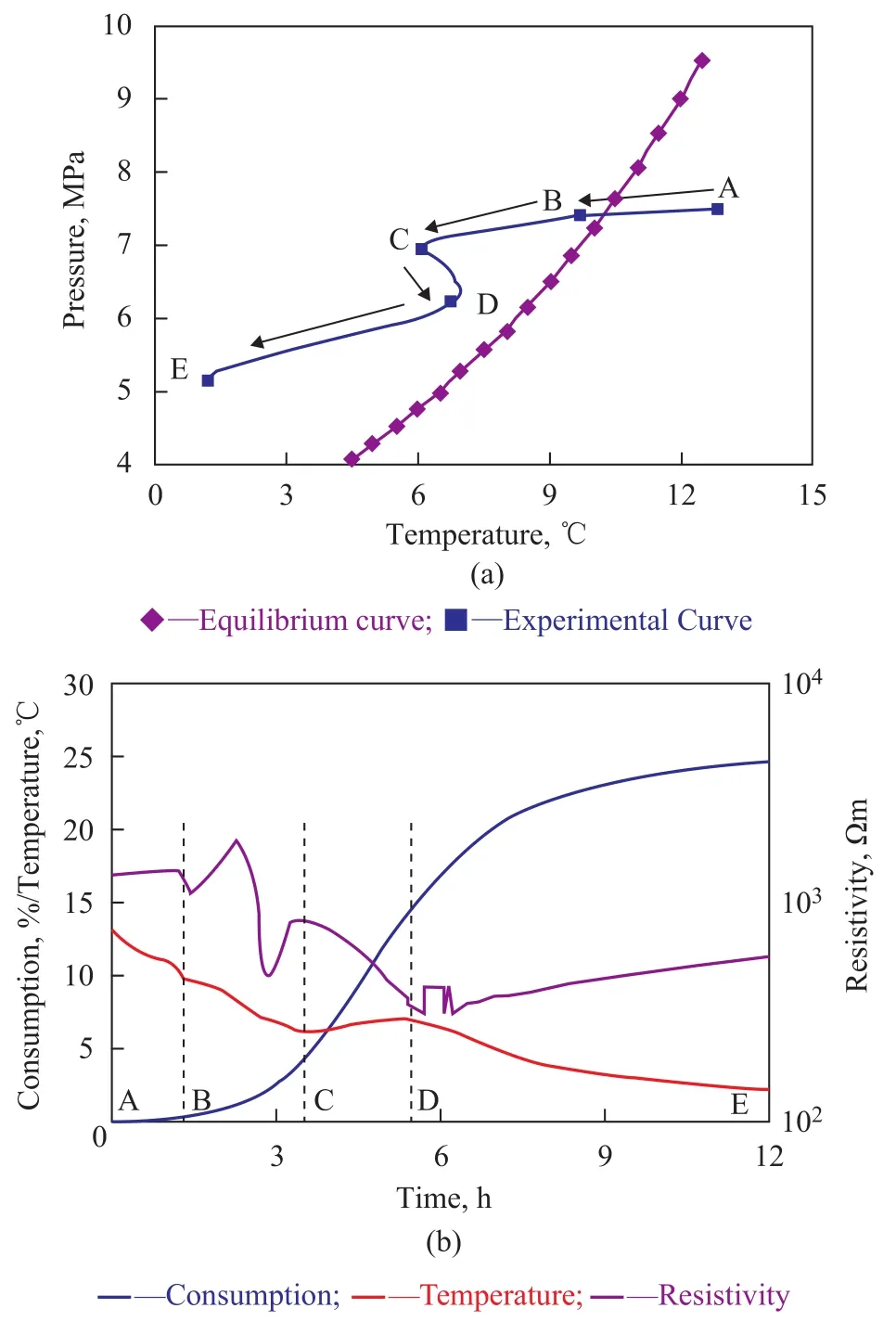
Figure 2 Temperature and pressure conditions of the first nucleation layer during the experiment and the relationships between temperature, resistivity, and gas consumption in the layer

Table 2 Volumetric water content of different layers before and after the experiment

Figure 3 Relationship between temperature and resistivity with reaction time at the top (the 10th layer), in the middle (the 5th layer), and at the bottom (the 1st layer)

Table 3 Nucleation time (tn) determined by temperature and resistivity
3.2 Effects of temperature gradient and cooling rate on hydrate nucleation time
Figure 4 and Figure 5 respectively show the nucleation time of methane hydrates that were formed in different sand layers at various cooling rates and temperature gradients. Figures 4A and 4B show the nucleation time of gas hydrate in the different layers of samples when the temperature gradients changed from 0 ℃/cm to 0.18 ℃/cm and the cooling rates varied from 2 ℃/h, 4 ℃/h, and 8 ℃/h, respectively. Figure 5 shows the nucleation time of hydrate in the different layers under different temperature gradients. As shown by Figure 4A, when the temperature gradient was 0 ℃/cm, the cooling rate significantly affected the nucleation time of the hydrates in different layers of samples. At a cooling rate of 2 ℃/h, the hydrate nucleation time increased in the following order: the bottom layer sand < the middle layer sand < the top layer sand. At a cooling rate of 4 ℃/h, the hydrate nucleation time decreased from the bottom to the top layer of the sand in the reactor. At a cooling rate of 8 ℃/h, the hydrate nucleation time was the longest in the middle-layer sand compared with that in the bottom-layer sand and the top-layer sand. It can be seen from Figure 4B that when the temperaturegradient was 0.18 ℃/cm, the effect of the cooling rate on hydrate nucleation time was relatively reduced. It can be seen from Figure 5 that under the same cooling rate with an increasing temperature gradient, the hydrate nucleation time was shortened. At a temperature gradient of 0.11 ℃/cm, the nucleation time was a minimum. At a cooling rate of 8 ℃/h, the effect of the temperature gradient on nucleation time decreased. With regard to the first nucleation layer, the nucleation time was reduced with an increasing cooling rate. Generally speaking, a higher cooling rate corresponds to a shorter nucleation time. However, when the cooling rate was relatively low, the temperature gradient played a decisive role in the nucleation time. Therefore, a larger temperature gradient corresponds to a shorter nucleation time and an easier formation of methane hydrate.
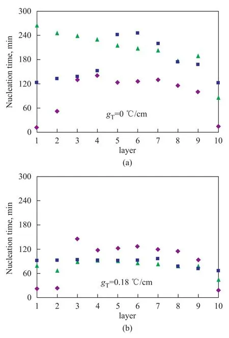
Figure 4 Relationship between cooling rate and nucleation time of each layer
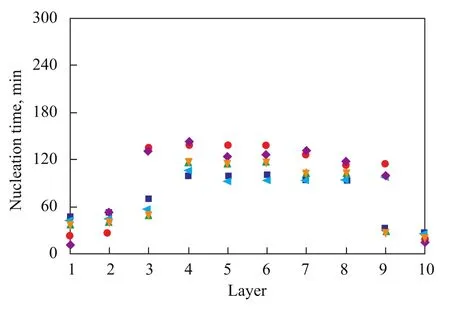
Figure 5 Relationship between temperature gradients and nucleation time of each layer

Figure 6 Undercooling at different temperature gradients and cooling rates
Figure 6 shows the degree of undercooling corresponding to the first nucleation point obtained at different cooling rates and temperature gradients. The nucleation of gas hydrates takes place at a certain temperature and pressure. The degree of undercooling refers to the difference between the equilibrium temperature corresponding to the pressure and actual reaction temperature. The degree of undercooling also represents the temperature as the driving force required by the hydrate reaction. The temperature gradient and the cooling rate showed thecomplicated effects on the degree of undercooling. The cooling rate affected the undercooling irregularly at the temperature gradient of 0 ℃/cm and 0.18 ℃/cm, respectively, as shown in Figure 6(a). At 0.18 ℃/cm, a lower cooling rate corresponds to a higher degree of undercooling. At a temperature gradient of 0 ℃/cm, a higher cooling rate corresponds to a higher degree of undercooling. With an increasing temperature gradient the degree of undercooling increases, except that the undercooling degree is abnormal at the temperature gradient of 0 ℃/cm in the Figure 6B.
3.3 Effects of cooling rate and temperature gradient on hydrate formation rate
The rate of methane hydrate formation is expressed in terms of the consumption of methane gas per minute during the reaction. In the course of methane hydrate formation, water and methane were filled into the remaining space of the reaction cells. The initial temperature and pressure wereT1(℃) andP1(MPa), respectively. The mole of gaseous methane in the system can be calculated as follows:

whereVg1is the volume occupied by methane gas (mL), andZis gas compressibility that can be calculated by the Redlich–Kwong equation of state.

In this experimental process, the formation of gas hydrate was in an isochoric condition. Thus, the volume of water and gas before hydrate formation is equal to the volume of water, gas, and hydrate after hydrate formation. Under the standard condition, a unit volume of gas hydrate can be decomposed to 164-unit volume of methane gas and 0.8-unit volume of water. If the temperature and pressure vary fromT1toT2and fromP1toP2,respectively, Δn(in mole of methane) is consumed in the hydrate formation process. The volume of methaneVgsunder the standard condition can be calculated as follows:

in whichVg1is the gas volume measured at the initial state (cm3).

Figure 7 Hydrate formation rate at different temperature gradients
Figure 7 compares the effect of different temperature gradients and cooling rates on methane hydrate formation rate in coarse sand. Figures 7(a) to 7(c) show the effect of temperature gradients on the hydrate formation rate at different cooling rates. Under the same cooling rate, a largertemperature gradient is conducive to the improvement of the formation rate and the reduction of the time required for methane hydrate formation. Figure 8 shows the effect of the cooling rate on the hydrate formation rate. Under the same temperature gradient, the cooling rate shows no obvious trend in affecting the hydrate formation rate. For an average rate of hydrate formation at a temperature gradient of 0 ℃/cm, a higher cooling rate would lead to a higher hydrate formation rate. However, at a temperature gradient of 0.18 ℃/cm, the cooling rate has no obvious effect on hydrate formation rate (Table 4). These results indicate that the temperature gradient has a stronger effect on the hydrate formation rate as compared with the cooling rate.

Figure 8 Hydrate formation rate obtained at different cooling rates

Table 4 Average methane hydrate formation rate at different temperature gradients and cooling rates
3.4 Effects of temperature gradient and cooling rate on hydrate distribution
Figure 9 and Figure 10 show the distribution of temperature and resistivity in the reactor obtained at different temperature gradients and cooling rates, which indicate the distribution of methane hydrates in the coarse sand. Profiles a and b in the Figs. 9 and 10 refer to the temperature distribution and resistivity distribution, respectively. Substantial methane hydrates were formed within 4 h after start of the reaction, during which the temperature rapidly decreased and the resistivity changed very little. Prior to the formation of methane hydrates, the resistivity decreased to an extremely low value within the first 20 h. The resistivity reached an extremely large value in different regions of the reactor after 20 h, thus indicating to the enrichment of methane hydrates in these areas. Figure 9 shows the temperature distribution, indicating that a minimum temperature of -1.7 ℃ was identified at the top and a temperature of +1 ℃ was measured at the bottom. Tpynak (1945)[28]indicated that the freezing point of water can be determined by the second law of thermodynamics (the Clapeyron-Clasius Equation). The freezing point of water decreases by 0.0075 ℃ when pressure increase by 0.1 MPa. In this paper, when the hydrate reaction system is in an equilibrium state, and the pressure ranges from 6 MPa to 7 MPa, the freezing point of water is between -0.6 ℃ and -0.7 ℃. From the viewpoint of the temperature regime of most test samples, the temperature of soil layer with the highest resistivity is higher than -0.7 ℃, which indicates that there is no ice in the soil layer. During the experiment, there are two reasons responsible for the change of sample’s resistivity. One is the freezing of water; the other is the formation of gas hydrate. When the ice does not form in the soil layer, it is concluded that the formation and enrichment of gas hydrate in the specified section of test samples result in the increase of resistivity. According to the conclusion, Fig.9 indicates that different temperature gradients make hydrate gather in the different layers of samples. Gas hydrate gathers at the bottom when the temperature gradient reached 0.02 ℃/cm, 0.07 ℃/cm and 0.11 ℃/cm, respectively. Judging fromthe degree of uniformity, the distribution of gas hydrate at a temperature gradient of 0.07 ℃/cm was the most uniform among all samples. It can be seen from Figure 10 that at a temperature gradient of 0 ℃/cm the distribution of methane hydrates formed at three different cooling rates showed substantial differences, demonstrating that the enrichment of gas hydrate in the upper, middle-bottom, and middleupper parts of the reactor did occur at the cooling rate of 2 ℃/h, 4 ℃/h, and 8 ℃/h, respectively. At a temperature gradient of 0.18 ℃/cm, gas hydrate enrichment was observed in the upper and middle-upper part at a cooling rate of 2 ℃/h and 8 ℃/h, respectively; uniform enrichment was observed at a cooling rate of 4 ℃/h. With regard to the location of gas hydrate enrichment, substantial differences were identified at different cooling rates. At a cooling rate of 4 ℃/h, variations in the temperature gradient led to different patterns of methane hydrate distribution. This result indicates that the temperature gradient affects the distribution of methane hydrate despite a relatively weaker effect compared with that of the cooling rate.
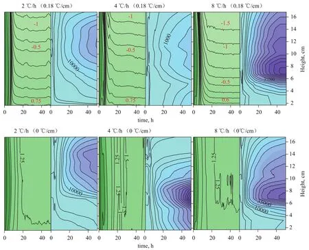
Figure 10 Distribution of temperature and resistivity obtained at different cooling rates
3.5 Effects of temperature gradient and cooling rate on hydrate saturation
Under standard conditions, the unit volume of gas hydrate can be decomposed to 164-unit volume of methane gas and 0.8-unit volume of water. Assuming that all hydrates were formed in sand pores, the saturation of sand with gas hydrate is expressed as follows:

whereVis the pore volume of sand without water.
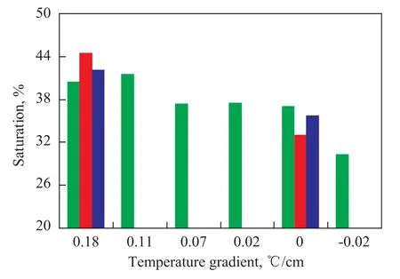
Figure 11 Effects of temperature gradient and cooling rate on hydrate saturation
Figure 11 shows the relationship of the saturation of coarse sand with methane hydrate formed at different temperature gradients and cooling rates. The methane hydrate saturation rate of sand at a temperature gradient of 0.18 ℃/cm exceeded that obtained at a temperature gradient of 0 ℃/cm. However, at the same temperature gradient, the cooling rate showed no obvious effect on hydrate saturation of sand. This result indicates that the temperature gradient has a stronger effect on hydrate saturation of sand than the cooling rate.
4 Conclusions
(1) Electrical resistivity is highly sensitive to the nucleation, formation, and moisture migration of methane hydrates. Thus, temperature and resistivity can be combined for the accurate determination of hydrate nucleation and formation.
(2) The cooling rate and temperature gradient both have obvious effects on the nucleation time and degree of supercooling of methane hydrates. At a small temperature gradient, the cooling rate exhibits a strong effect on hydrate nucleation time. At a large temperature gradient, the effect of cooling rate on hydrate nucleation time is weakened.
(3) A large temperature gradient is conducive to the improvement of the methane hydrate formation rate. The cooling rate has no obvious effect on hydrate formation rate.
(4) The temperature gradient has a certain effect on the distribution of methane hydrates. However, this effect is relatively weak compared with that of the cooling rate.
(5) At the same temperature gradient and cooling rate, the cooling rate shows no obvious effect on hydrate saturation of sand. At the same cooling rate, a greater temperature gradient indicates a larger extent of saturation of sand with methane hydrates.
Acknowledgements:This research was supported by the Chinese Academy of Sciences Action-plan for Western Project (No. KZCX2-XB3-03), the National Natural Science Foundation of China (No. 41001038, 51266005) and the National Natural Science Foundation of China ( No. 41101070, 1106ZBB007).
[1] Sloan E D. Fundamental principles and applications of natural gas hydrates[J]. Nature, 2003, 426 (6964): 353–359
[2] Collett T S. Energy Resource Potential of Natural Gas Hydrates[J]. AAPG Bulletin, 2002, 86(11): 1971-1992
[3] Makogon Y F. Hydrates of Natural Gas [M]. Tulsa: Penn Well, 1981: 160
[4] Bower P G. Deep ocean field tests of methane hydrate formation from a remotely operated vehicle[J]. Geology, 1997, 25(5): 407-410
[5] Chuvilin E M, Yakushev V S, Perlova E V. Experimental study of gas hydrate formation in porous media [J]. VNIIGAN, 1999(9): 431-440
[6] Smith D H, Wilder J W, Seshadri J. Methane hydrate equilibria in silica gels with broad pore-size distributions [J]. AIChE Journal, 2002, 48(2): 393-400
[7] Zhao H W, Diao S B, Ye Y G, et al. Technique of detecting impedance of hydrate in porous medium[J]. Marine Geology & Quaternary Geology, 2005, 25(1): 137-142
[8] Fan S S, Liu F, Chen D F, The research of the origin mechanism of marine gas hydrate[J]. Natural Gas Geoscience, 2004, 15(5): 524-530 (in Chinese)
[9] Chen M, Cao Z M, Ye Y G, Liu C L. Experimental technology on elemental geochemical study during the formation of marine gas hydrates[J]. Acta Oceanologica Sinica, 2006, 28(6): 39-43 (in Chinese)
[10] Liu F, Fan S S. A Study on Formation of Methane Hydrate in Sea Mud-Sand Sediment [J]. Natural Gas Chemical Industry, 2005, 30(2): 22-27 (in Chinese)
[11] Wu Q B, Pu Y B, Jiang G L, Xing L L. Experimental research of formation process of methane hydrate in freezing coarse-grain sand by computerized tomography [J]. Natural Gas Geoscience, 2006, 17(2): 239-243 (in Chinese)
[12] Jiang G L, Wu Q B, Pu Y B. The effects of cooling process on the formation of methane hydrate within the coarse sand [J]. Chinese Journal of Geophysics, 2009, 52(9): 2387-2393 (in Chinese)
[13] Zhang P, Wu Q B, Jiang G L. Effects of temperature reducing ratios on methane hydrate formation inside media above zero degree celsius [J]. Natural Gas Geoscience, 2009, 20 (6): 1000-1004 (in Chinese)
[14] Collett T S, Bird K J, Kvenvolden K A. Geological interrelations relative to gas hydrates within the North Slope of Alaska[C]//MUS Geological Survey. Open File Report, 1988, 150: 882-389.
[15] Handa Y P, Stupin D. Thermodynamic properties and dissociation characteristics of methane and propane hydrates in 70-Å-radius silica-gel pores[J]. J Phys Chem, 1992, 96(21): 8599-8603.
[16] Ruppel C. Anomalously cold temperatures observed at the base of the gas hydrate stability zone on the U.S. Atlantic passive margin[J]. Geology, 1997, 25(8): 699-702.
[17] Tréhu A M,Bohrmann G, Rack F.Leg 204 Scientific Party, Proc. ODP, Initial Reports, 204 [CD]. Available from: Ocean Drilling Program, Texas A&M University, College Station TX 2003. 7845-9547
[18] Pearson C F, Halleck P M, McGuire P L. Natural gas hydrate deposits: A review of in situ properties[J]. Journal of Physical Chemistry, 1983, 87(21): 4180-4185
[19] Hyndman R D, Yuan T, Moran K. The concentration of deep sea gas hydrates from down hole electrical resistivity logs and laboratory data[J]. Earth and Planetary Science Letters, 1999, 172(1): 167-177
[20] Buffett B.A, Zatsepina O Y. Experiment study of the stability of CO2-hydrate in a porous medium[J]. Fluid Phase Equilibria, 2001, 192: 85-102
[21] Zatsepina O Ye, Buffett B.A. Nucleation of CO2-hydrate in a porous medium [J]. Fluid Phase Equilibria, 2002, 200(2): 263-275
[22] Spangenberg E, Kulenkampf J. Influence of methane hydrates content on electrical sediment properties [J]. Geophysical Research Letters, 2006, 33:243-251
[23] Gabitto J F, Tsouris C. Physical properties of gas hydrates: A review[J]. Journal of Thermodynamics, 2010, 271291
[24] Cha S B, Ouar H, Wildeman T R. A third surface effect on hydrate formation[J]. The Journal of Physical Chemistry, 1988, 92 (23): 6492-6494
[25] Kashchieve D, Verdoes D, Von Rosmalen G M. Induction time and metastability limit in new phase formation [J]. Journal of Crystal Growth, 1991, 110: 373-380
[26] Stern L A, Kirby S H, Circone S. Scanning electron microscopy investigations of laboratory grown gas clathrate hydrates formed from melting ice, and comparison to natural hydrates[J]. American Mineralogist, 2004, 89: 1162-1175
[27] Chen M, Ye Y G, Wan J. Methane hydrate formation and dissociation in porous media formed in a synthetic capillary tube[J]. Geoscience, 2010, 24 (3): 632-637
[28] Tpyпακ H Г. Freezing Shaft Sinking Method (RUDIN). Translated by Beijing Institute of Mining Shaft Engineering Teaching and Research Group [M]. Beijing: China Coal Industry Publishing House. 1954: 28-59
Recieved date: 2013-01-31; Accepted date: 2013-04-19.
Wu Qingbai, Tel: +86-931-4967284; E-mail: qbwu@lzb.ac.cn.
- 中国炼油与石油化工的其它文章
- Preparation and Catalytic Performance of Potassium Titanate Used as Soot Oxidation Catalyst
- A Probe into Process for Maximization of Low-carbon Olefins via Co-processing of Methanol and Heavy Oil
- Influence of Carbon Content on S Zorb Sorbent Activity
- Propylene Polymerization Catalysts with Sulfonyl Amines as Internal Electron Donors
- Isolation and Characterization of a Thermophilic Oil-Degrading Bacterial Consortium
- Research on Catalytic Properties of Palladium Catalyst Prepared by Biological Reduction Method

