
Fin characteristics of aerator devices with lateral deflectors*
2013-06-01 12:29:57WUJianhua吴建华LIDan李丹MAFei马飞QIANShangtuo钱尚托
水动力学研究与进展 B辑 2013年2期
WU Jian-hua (吴建华), LI Dan (李丹), MA Fei (马飞), QIAN Shang-tuo (钱尚托)
College of Water Conservancy and Hydropower Engineering, Hohai University, Nanjing 210098, China,
E-mail: jhwu@hhu.edu.cn
Fin characteristics of aerator devices with lateral deflectors*
WU Jian-hua (吴建华), LI Dan (李丹), MA Fei (马飞), QIAN Shang-tuo (钱尚托)
College of Water Conservancy and Hydropower Engineering, Hohai University, Nanjing 210098, China,
E-mail: jhwu@hhu.edu.cn
(Received March 16, 2013, Revised April 1, 2013)
The fins will be formed if the lateral deflectors in the side-walls with a bottom aerator device are improperly designed, and the flow regime downstream of the aerator device will be worsened. In this paper, the height and the length of the fins induced by the lateral deflectors are theoretically analyzed along with their influencing factors, and the fin characteristics are experimentally investigated on the basis of the theoretical analysis. It is shown that the intensities of the fins are strongly dependent on the ratio of the lateral cavity length to the bottom cavity length, and other factors, like the working head, the height and the angle of the lateral deflector, the flow Froude number around the aerator device, affect the fins indirectly through the changes of the lateral cavity length. When an aerator device with lateral deflectors is designed, it is crucial to match the above mentioned ratio, and to make the ratio of the two cavity lengths less than 1.0 in order to avoid the generation of the fins.
aerator, cavity length, fin, lateral deflector
Introduction
In recent more than 10 years, the air entrainment from the full section, as an interesting issue, was mainly investigated in the context of the cavitation damage control of release works. The air is entrained into the flow through not only the bottom aerator but also the lateral deflectors on the side-walls. It was shown to be effective to use this measure for prevention of this damage of the side-walls, as well as the bottom, when the damage occurred and was repaired for the discharge tunnel No.1 for the Ertan hydropower station in 2001[1,2]. However, the fins are easily generated due to the placement of the lateral deflectors, and worsen the flow regimes downstream of the aerator devices.
The fin or the water-wing is a kind of flow phenomena, and would badly affect the operation of the release works. It usually occurs where the structural boundary changes abruptly, such as in the stepped spillways[3,4], the outlets of service gates with lateral enlargements[5,6], and at the tail part of the middle pier for discharge tunnels[7,8]. The studies of the fin phenomena mainly focus on the hydraulic characteristics and the preventing measures. For the steep stepped spillway, such as that with a slope over 40o, the fins are easily formed when the flow discharge is low over it[9], which is related to the flow patterns, as well as the step geometric and hydraulic parameters[10,11]. For the fins downstream of the outlet of the service gate, it is shown that the location of the maximum height moves downstream, and the intensities of the fins, including the height and the length, increase remarkably, when the working head increases[12]. For the fins induced by the middle pier, the two technologies were developed to control and weaken those fins based on the conversions of the concentrating force into the separating ones, and the modification of the concave surface of the flow near the tail of the pier[7,13]. In order to prevent the occurrence of the fins induced by the lateral deflectors, however, it is necessary to investigate the hydraulic characteristics of the fins. This paper makes a theoretical analysis of the factors influencing the fins, and explores the conditions of the generation of fins by means of physical model experiments.
1. Theoretical consideration
According to the experimental observations, the flow through the aerator device could be described byFig.1, with the geometric parameters of the aerator including αBand trBas the angle and the height of the bottom ramp, respectively,i as the bottom slope, and αLand trLas the angle and the height of the lateral deflector with respect to the side-wall, respectively, with the hydraulic parameters includingdoand Voas the depth and the average velocity of the approach flow, respectively,LCBas the bottom cavity length, LCLas the lateral cavity length, and with the fin characteristics being expressed in terms of the height (HF)and the length (LF).

Fig.1 Sketch of flow regime
The height (HF)and the length (LF)of the fins are functions of the geometric parameters of the aerator and the hydraulic parameters of the flow, as

whereHois the working head of the weir crest for spillways. For a given bottom aerator device,i,αBand trBare all constants, and Eq.(1) could be rewritten in dimensionless variables as

where Fro=Vo/(gdo)0.5is the Froude number of the flow through the aerator, andβLB=LCL/LCB, is the ratio of the lateral and bottom cavity lengths.
2. Experimental set-up and cases
2.1 Experimental set-up
The experiments were conducted in the Highspeed Flow Laboratory of Hohai University, Nanjing, China. The physical model was designed in scale of 1/ 40 according to the spillway of the Jiangpinghe hydropower station based upon the Froude number criterion. Figure 2 shows the experimental setup and the model for the spillway used in this study. It consists of a pump, an approach conduit, a large feeding basin, a model of the spillway, and a flow return system. The model of the spillway, made of perspex, is 0.35 m wide and 20.00 m long. The aerator device was placed at 6.50 m horizontally to the inlet of the spillway, and at 2.15 m vertically to the weir crest of the inlet. The maximum pump capacity was 400 L/s, and the working head was 0.75 m. The water discharges were measured with discharge measurement weir instruments downstream of the experimental model. In the experiments, the bottom slope was 1:10 at the location of the aerator device, corresponding to i =5.71o.
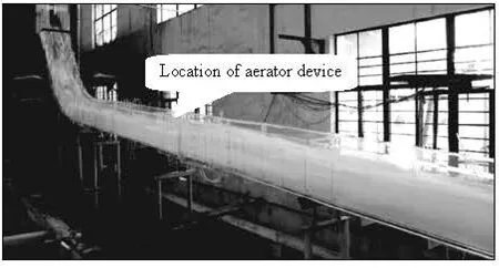
Fig.2 Sketch of experimental set-up
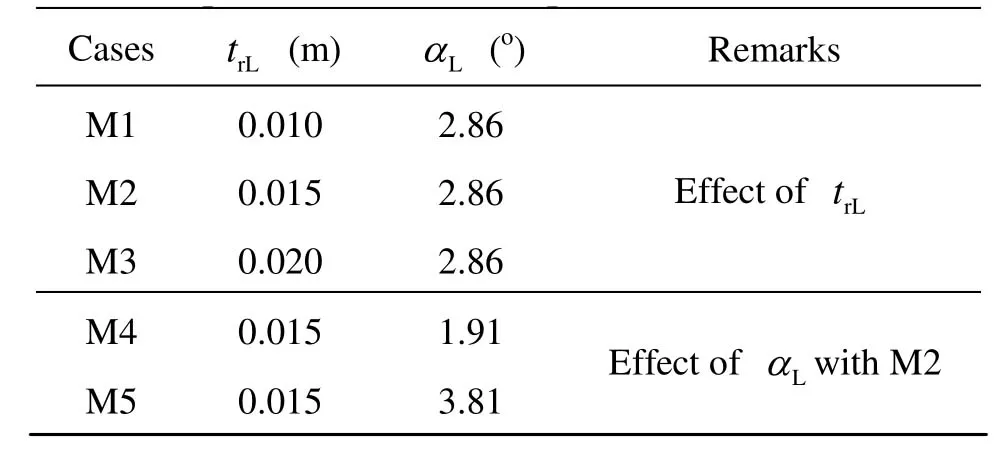
Table 1 Experimental cases and parameters
2.2 Experimental cases
Table 1 lists the experimental cases and the geometric parameters of the model lateral deflectors. The parameters were designed to investigate the effects on the fin characteristics below the aerator device. Cases M1-M3 were for the effects of trL, and Cases M2, M4 and M5 were for the effects of αL. The geometry of the bottom aerator was given by:trB=0.04 m and αrB=5.71o(1:10). The measured parameters include the working head (Ho), the approach flow depth (do) and velocity (Vo), the bottom and lateral cavity lengths (LCBand LCL), and the height (HF)and length (LF)of the fin.
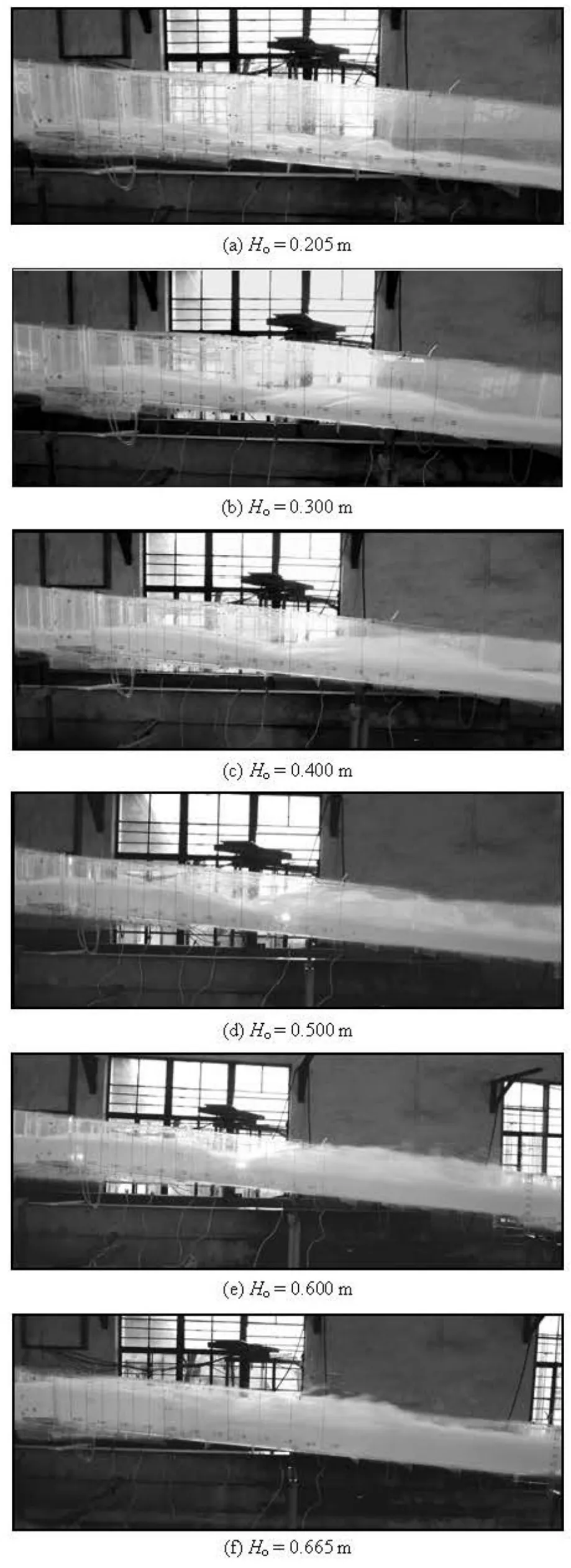
Fig.3 Fin phenomena (Model M2)
3. Results and discussions
3.1 Observation of fins
The flow regimes around the aerator device and the fins downstream of the lateral cavity were experimentally observed for the cases listed in Table 1. Figure 3 shows the fin phenomena in the different working heads (Ho)for model M2, and the occurrence and the development of the fins could be clearly seen.
Firstly, the inception location of the fins appears at the tail part of the lateral cavity. Secondly, either the height(HF)or the length (LF)increases with the increase of the heads. There exist the maximum values for them, but they occur not at the same head, for example, with respect to model M2, the highest height of the fin occurs at the head of 0.40 m (Fig.3(c)), while the longest length of it at the head of 0.50 m (Fig.3(d)). Finally, it could be noticed that the fins may be violent and higher than the height of the walls, to strike the top of the release works (Fig.3(e) and 3(f)).

Fig.4 Variation of HF/trBwith Ho/trBfor different heights of lateral deflectors

Fig.5 Variation of LF/trBwith Ho/trBfor different heights of lateral deflectors
3.2 Effects of lateral deflector geometry
On the basis of Eq.(2), the effects of the height and the angle of lateral deflectors were experimentally investigated. Figures 4 and 5 show the variations of HF/trBand LF/trBwith Ho/trBfor the different heights of lateral deflectors, and Figs.6 and 7 show the variations ofHF/trBand LF/trBwith Ho/trBfor the different angles of lateral deflectors, respectively.From those figures, it could be clearly seen that, the higher height or the larger angle of the lateral deflectors could both produce higher fin height (HF)and longer fin length (LF)at different heads, for example, either the height or the length of the fins of model M3 is larger than that of model M1 for the different heights of the lateral deflectors, and those of model M5 is larger than those of model M4 for different angles.
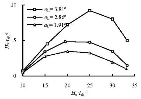
Fig. 6 Variation of HF/trBwith Ho/trBfor different angles of lateral deflectors
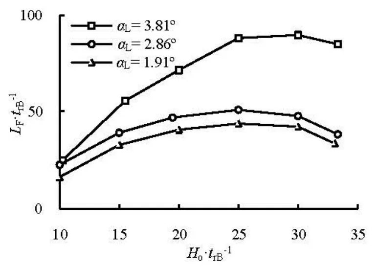
Fig. 7 Variation of LF/trBwith Ho/trBfor different angles of lateral deflectors
On the other hand, as mentioned before, the maximum values of the fin characteristics do not appear at the same working heads. For example, for model M3, the maximum height of HF/trB=8.5is at Ho/trB=24.9(see Fig.4), while the maximum length of LF/trB=71.0at Ho/trB=30.0(see Fig.5). The similar phenomena occur for the effects of the angles on the fin characteristics (see Figs.6 and 7).
In addition, it could be noticed that, the increment of the fin characteristics, either the height (HF) or the length(LF), is not uniform for different angles of the lateral deflectors. For example, the small increase appears fromαL=1.91oto 2.86o, while large changes take place at αL=3.81o. It seems that there is a critical angle in the changes of the angles of lateral deflectors (see Figs.6 and 7).
According to the experimental observations, the fins induced by the lateral deflector originate from the tail of the lateral cavity, so the effects of height or angle of the lateral deflector on the fin characteristics may be attributed to the length of the lateral cavity. Since the lateral cavity length is strongly related to the lateral deflector geometry, it is important to investigate the relationship between the lateral cavity length and the lateral deflector form and other related factors.
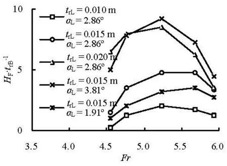
Fig.8 Variation of HF/trBwith Fr

Fig.9 Variation of LF/trBwith Fr
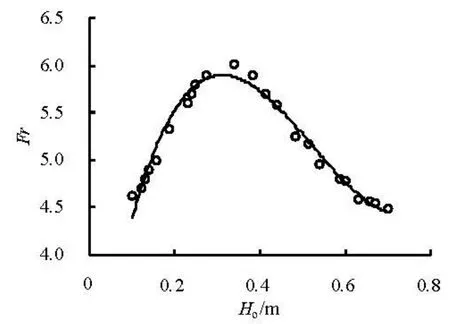
Fig.10 Variation of Fr with Hoat location of aerator device[15]
3.3 Effects of Froude number

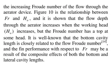

Fig.11 Variation of HF/trBwith βLB
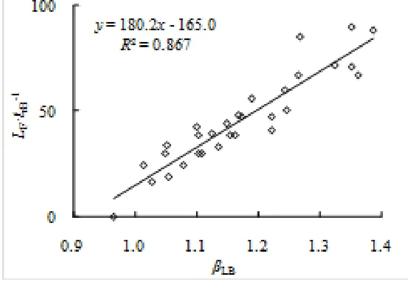
Fig.12 Variation of LF/trBwith βLB
3.4 Effects of cavity length ratio
The ratio of the lateral and bottom cavity lengths, as an important factor, was investigated, and Figs.11 and 12 show the variations of HF/trBand LF/trBwith βLB. It could be seen that both HF/trBand LF/trBhave good linear relationships with βLBwhen βLB>1.0. Based on the data, we have:
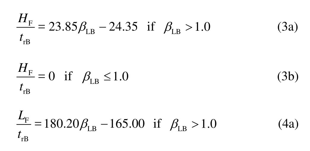
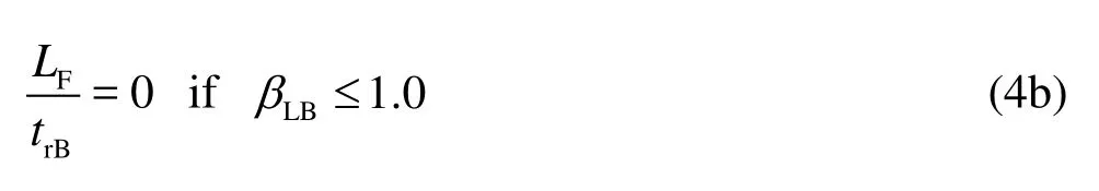
They include two aspects of information: one is that the occurrence and the development of the fins are related to the magnitude of βLB, that is, not only to the lateral cavity length, but also to the bottom cavity length, and the larger the magnitude of βLB, the more intensive the fins will be, the other is that the fins can be eliminated when βLB≤1.0. Therefore, it is crucial to match the lateral cavity length with the bottom cavity length when the lateral deflectors are designed in order to avoid the generation of the fins.
4. Conclusions
For a given geometry of the bottom aerator, the fin characteristics, both its height and length, are functions of the working head, the height and the angle of the lateral deflector, the flow Froude number around the aerator, and the ratio of the lateral cavity length to the bottom cavity length.
In those influencing factors of the fin performance, it is the ratio of the lateral cavity length to the bottom cavity length that has the dominant bearing on the occurrence and the development of the fins, while the other factors, like the working head, the height and the angle of the lateral deflector, the flow Froude number around the aerator, would affect the lateral cavity length, then indirectly affect the fin performance through the ratio of the two cavity lengths.
The height and the length of the fins are approximately proportional to the ratio (βLB), and the larger the magnitude of βLB, the more intensive the fins will be. When an aerator device is designed, one should match the above mentioned ratio. The condition of βLB≤1.0must be met to avoid the generation of the fins induced by the lateral deflector. So, the geometries of the bottom aerator and the lateral deflector should be overally considered to achieve this purpose.
[1] CHEN Wen-xue, XIE Sheng-zong and LIU Zhi-ping et al. Aeration device on lateral walls for the discharge tunnel with inclined inlet[J]. Hydropower, 2005, 31(4): 31-34(in Chinese).
[2] LIU Chao, YANG Yong-quan and DENG Jun et al. Experimental study on air entrainment to alleviate cavitations for downstream sidewalls of ogee-section in spillway tunnel[J]. Chinese Journal of Hydrodynamics, 2006, 21(4): 465-472(in Chinese).
[3] SORENSEN R. M. Stepped spillway hydraulic model investigation[J]. Journal of Hydraulic Engineering, ASCE, 1985, 111(12): 1461-1472.
[4] CHANSON H. Stepped spillway flows and air entrainment[J]. Canadian Journal of Civil Engineering, 1993, 20(3): 422-435.
[5] CHEN Qing-sheng, REN Xu-hua and YUAN Yingzhong. Experimental study on hydraulics of gate with flexible water seal in Ertan project[J]. Journal of Hohai University (Natural Sciences), 1995, 23(4): 56-61(in Chinese).
[6] NIE Meng-xi, WU Guang-hao. Effect of lateral deflector on aeration in bottom and lateral cavities of flows over spillways[J]. Journal of Tsinghua University (Science and Technology), 2003, 43(8): 1116-1119(in Chinese).
[7] WU Jian-hua, CAI Chang-guang and JI Wei et al. Experimental study on cavitation and water-wing for middlepiers of discharge tunnels[J]. Journal of Hydrodynamics, 2005, 17(4): 429-437.
[8] JI Wei. Water-wings and preventions of middle piers for discharge tunnels[D]. Master Thesis, Nanjing, China: Hohai University, 2006(in Chinese).
[9] RAJARATNAM N. Skimming flow in stepped spillway[J]. Journal of Hydraulic Engineering, ASCE, 1990, 116(4): 587-591.
[10] BOES R. M., HAGER W. H. Two phase flow characteristics of stepped spillway[J]. Journal of Hydraulic Engineering, ASCE, 2003, 129(9): 661-670.
[11] HAN Yu, FENG Rui-lin and TIAN Jia-ning et al. Water-wing on steep slope of stepped spillway[J]. Journal of Hydroelectric Engineering, 2006, 25(1): 114-118(in Chinese).
[12] NIE Meng-xi, WU Guang-hao. Effect of lateral deflector on cavity design[J]. Journal of Tsinghua University (Science and Technology), 2002, 42(4): 546-550(in Chinese).
[13] WU Jian-hua, YAN Zhong-min. Hydraulic characteristics of bottom underlay-type pier water-wing control[J]. Journal of Hydrodynamics, 2008, 20(6): 735-740.
[14] SUN Shuang-ke, YANG Jia-wei and LIU Hai-tao. Forms of aerator devices for mild slope[J]. Water Resources and Hydropower Engineering, 2004, 35(11): 26-29(in Chinese).
[15] WU Jian-hua, MA Fei. Cavity flow regime for spillway aerators[J]. Science China Technological Sciences, 2013, 56(4): 818-823.
10.1016/S1001-6058(13)60361-3
* Project supported by the National Basic Research Development Program of China (973 Program, Grant No. 2012CB723200), the National Natural Science Foundation of China (Grant No. 510879021).
Biography: WU Jian-hua (1958-), Male, Ph. D., Professor
猜你喜欢
疯狂英语·读写版(2024年2期)2024-03-26 07:10:43
小天使·一年级语数英综合(2020年10期)2020-12-16 02:57:11
水动力学研究与进展 B辑(2018年5期)2018-10-27 09:11:40
故事作文·低年级(2018年9期)2018-09-17 18:35:32
故事作文·低年级(2018年6期)2018-07-04 16:39:22
智富时代(2018年3期)2018-06-11 16:10:44
水动力学研究与进展 B辑(2018年2期)2018-05-14 01:43:30
水动力学研究与进展 B辑(2017年3期)2017-06-07 08:22:46
读写算·小学低年级(2017年4期)2017-04-15 16:44:51
作文周刊·小学一年级版(2016年29期)2017-03-02 13:02:00

- 水动力学研究与进展 B辑的其它文章
- An experimental study on runup of two solitary waves on plane beaches*
- Electro-osmotic flow of a second-grade fluid in a porous microchannel subject to an AC electric field*
- Parametric instability of a liquid metal sessile drop under the action of low-frequency alternating magnetic fields*
- Influence of flow field on stability of throttled surge tanks with standpipe*
- Influence of emergent macrophyte (Phragmites australis) density on water turbulence and erosion of organic-rich sediment*
- Hydrodynamic performance of a vertical-axis tidal-current turbine with different preset angles of attack*