Numerical study of fatigue damage of asphalt concrete using cohesive zone model
Jin Guanglai Huang Xiaoming Zhang Sulong Liang Yanlong
(1School of Transportation, Southeast University, Nanjing 210096, China)(2Key Laboratory of Highway Engineering of Sichuan Province, Southwest Jiaotong University, Chengdu 610031, China)
Fatigue is one of the most common and complicated failures that can cause damage to engineering structures. Asphalt concrete as a type of widely used pavement materials is not exempt from this deleterious phenomenon and has to be assessed under fatigue loading. Traditional numerical methods have difficulties in simulating the damage initiation stage and crack propagation stage as a continuous process[1-4].
The concept of the cohesive zone model (CZM), initially put forward by Barrenblatt et al.[5-7], considers fracture to be a gradual phenomenon in which separation occurs between two adjacent virtual surfaces across an extended crack tip (cohesive zone) and is resisted by the cohesive force. Compared with other methods describing the fracture feature of materials, numerical analysis using the CZM has several advantages: 1) Both the damage initiation stage and the crack propagation stage are considered; 2) The singularity of the crack tip appearing in fracture mechanics can be eliminated; 3) Time and cost efficiency is highly improved by conducting damage analysis in a local area to simulate the failure of the whole structure.
Recently, the CZM has been gradually used in the fracture analysis of asphalt concrete. Soares et al.[8]simulated the crack propagation of asphalt concrete in the indirect tensile test using the CZM proposed by Tvergaard et al.[9]Song[10]employed a power-law CZM to describe the progressive softening and viscoelastic effects occurring in the fracture of asphalt concrete. Kim et al.[11]studied the specimen size dependency on the fracture of asphalt concrete using a discrete element method coupled with a bi-linear CZM. Caro et al.[12]used the CZM technique to simulate the moisture-induced fracture at the aggregate-matrix interfaces. Yin et al.[13]inserted cohesive elements into both mastic and the aggregate-mastic interfaces to simulate the fracture process in 2D and 3D specimens.
However, when it comes to the application of the CZM in the fatigue analysis of asphalt concrete, there is little work in this field, so more research should be made. Kim et al.[14]studied the fatigue cracking of asphalt concrete using a nonlinear viscoelastic CZM. A cohesive zone damage evolution function is introduced into the model based on the variation of fibril geometry.
The object of this study is to predict the fatigue failure of asphalt concrete. Integrated with the CZM, a fatigue damage evolution model is established to indicate the gradual degradation of cohesive properties of asphalt concrete under cyclic loading. The model is then implemented in the finite element software ABAQUS through a user-defined subroutine of material (UMAT). Based on the proposed model, indirect tensile fatigue test is finally simulated.
1 Cohesive Zone Model Under Cyclic Loading
A damage evolution model integrated with a bi-linear CZM is employed to characterize the fatigue fracture feature of asphalt concrete. During the first cycle of the repetitive loading, the material’s constitutive relationship is defined by the bi-linear CZM. Once unloading occurs, the damage evolution model is activated to describe constitutive properties during the following process of fatigue loading. As a result, the material’s constitutive relationship can be divided into two forms: the bi-linear CZM in the first cycle and the fatigue damage evolution model during the following cyclic loading.
1.1 Bi-linear CZM
The bi-linear CZM under monotonic loading has been widely used in many materials and it has been already implemented in the finite element software ABAQUS. The traction-separation constitutive equations in the bi-linear CZM can be defined as
Ifte<σcorδe<δc,

(1)
Ifδc<δe<δf,
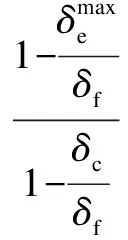
(2)

The features of the bi-linear constitutive relationship defined above are shown as segmentsOAandABin Fig.1. Under pure normal loading, cohesive traction increases with the increasing separation before the characteristic cohesive length is reached (shown byOA), and decreases subsequently until it approaches the zero traction line (shown byAB). Under pure shear loading, the traction-separation relationship is similar to that under pure normal loading. The cohesive fracture energyGcis computed by equating the area under the displacement-traction curve
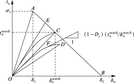
Fig.1 Traction-separation relationship under purenormal loading
(see Fig.1), namely

(3)
1.2 Fatigue damage evolution model
For the condition of cyclic loading, the constitutive relationship must be modified with a damage evolution model that characterizes the progressive degradation of cohesive properties in the cohesive failure zone under subcritical loading. The fatigue damage model should incorporate the following characteristics of continuum damage evolution: 1) Damage accumulation starts if a deformation measure, accumulated or current is greater than a critical magnitude. 2) The increment of damage is related to the increment of deformation as weighted by the current load level. 3) There exists an endurance limit which is a stress level below which cyclic loading can proceed without failure.
A fatigue damage variableDcis introduced into the fatigue model to define the degradation of stiffness as
(4)


To obtain the current state of damage, the derivation of fatigue damage in the current cycle is defined as
(5)

Eq.(5) indicates that during the process of any loading cycle, damage increases in the loading stage and resets to zero when the unloading begins. The speed of damage accumulation is related to the maximum stress level, the current stress level and separation increment. Parametersa,bandcare employed to describe different fatigue features between different types of asphalt concrete, among which parametercis used to characterize the high sensitivity of fatigue failure to stress level.
The fatigue CZM is implemented in the finite element code ABAQUS through UMAT subroutine. The location ofDc=1 is used to define the crack extension.
2 Experimental Test and Finite Element Model
2.1 Experimentaltest
Before the simulation, a laboratory fatigue test is conducted to obtain experimental records of the fatigue failure. A load-controlled mode is adopted in the test. The asphalt used here can be categorized as Shell AH-70. The aggregate gradation is listed in Tab.1. The semi-sinusoidal waveform is applied to the specimen with a loading frequency of 10 Hz. The temperature during the test is controlled at -10 ℃. A material testing machine, namely MTS 810, is used here to conduct the fatigue test. Tests are taken under four different stress ratios, 0.5, 0.6, 0.7 and 0.8.

Tab.1 Gradation used in experimental test
2.2 Finite element model
Indirect tensile test (IDT) is a common method to investigate the fatigue properties of asphalt concrete. Therefore, fatigue failure in the IDT specimen is simulated here. The radius of the specimen is 50.8 mm. In the finite element model, a row of cohesive elements with zero initial thickness is laid along the centerline of the specimen, where fatigue crack is initiated under cyclic loading. The constitutive response of the cohesive element is defined by the UMAT subroutine. For the rest of the specimen area, traditional plane strain elements are laid and the material’s constitutive response is defined as linear elasticity. Fig.2 shows the in-plane finite element mesh, in which a higher mesh density is used near the cohesive elements to obtain more accurate results. Because the load-controlled mode is usually applied to the IDT, only fatigue failure under this mode is investigated in this paper.
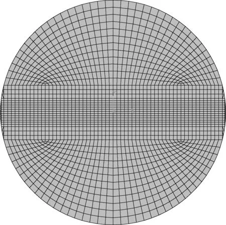
Fig.2 Finite element mesh
There are eight parameters in total needed to be determined (see Tab.2). The elastic modulusEis easy to be obtained by the IDT fracture test. Cohesive strength is the tensile strength which can be determined by the IDT and fracture energyGccan be determined by the single-edge notched beam test (SEB)[10]. Cohesive lengthδcis incorporated to reduce the elastic compliance by adjusting the pre-peak slope of the cohesive law. In other words, as the value ofδcdecreases, the pre-peak slope increases and as a result, artificial compliance can be reduced. In this paper,δc=0.01δfis used for asphalt concrete based on previous work by Song[10]. Failure displacement is obtained according to cohesive strength and fracture energy. Endurance limit is assumed to be 0.15. An informed iterative approach is adopted to determine appropriate fatigue model parametersaandc. Note that the laboratory test is conducted at -10 ℃.
3 Discussion
The most important information of a material’s fatigue property is the fatigue life under certain conditions. Using current CZM, the numerical results of fatigue lives are calculated and compared with the experimental results (see Fig.3). It can be observed that the predicted and measured fatigue lives agree very well, which demonstrates the effectiveness of the proposed model in predicting fatigue lives.
The fatigue damage that varies along the centerline of the IDT specimen at different loading cycles is shown in Fig.4 (stress ratior=0.6). It can be seen that the fatigue damage shows accurate symmetry about the center of the specimen, which is caused by the stress or strain symmetry of the specimen. At the specimen’s center, the maximum value of damage is obtained. But at the two ends

Tab.2 Mechanical properties and CZM parameters of asphalt concrete
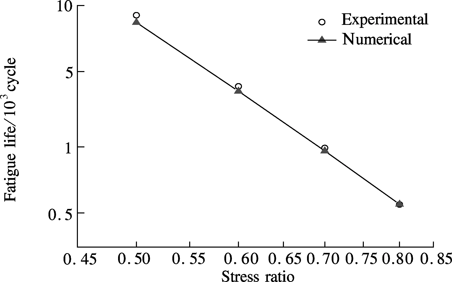
Fig.3 Comparison of the predicted and measured fatigue lives (log-log plot)
of the centerline, no damage exists because asphalt concrete in these areas is under compression. The three curves in Fig.4 are obtained at every 150 cycles. It can be seen that damage increases faster in the latter 150 cycles than in the former 150 cycles. WhenN=2 500, fatigue damage reaches 1 near the center, which indicates that there is a macrocrack with a length of 3 mm. Considering that fatigue failure occurs atN=2 550, it can be concluded that the time of crack propagation phase is much shorter than that of the damage initiation phase.
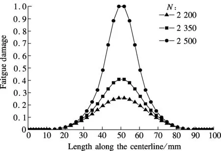
Fig.4 Distribution of fatigue damage along the centerline at three loading cycles
Fig.5 shows the fatigue damage variations during the cyclic loading process at the center of the specimen. In the whole process, damage accumulates in a nonlinear manner, which can be divided into steady growth stage and rapid growth stage. Note that when the damage reaches 0.3, the speed of damage growth increases significantly and an initial crack occurs soon in the specimen. For the specimen under a higher stress ratio (i.e.r=0.8), damage growth maintains a high speed in the whole process and the time of the steady growth stage is much shorter than that of specimen under lower stress ratio.
Because fatigue damage is coupled with the material’s mechanic properties, the constitutive response of asphalt concrete changes from cycle to cycle. As shown in Fig.6,
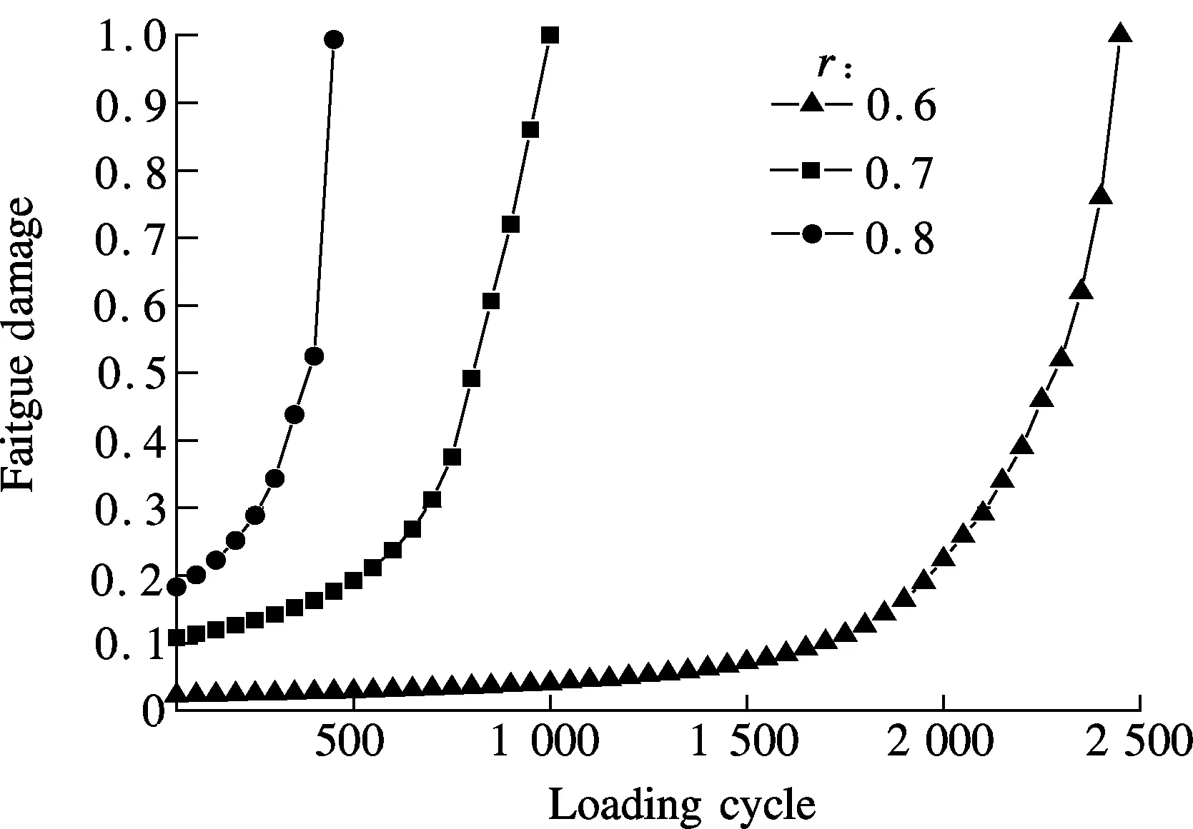
Fig.5 Damage growth at the center of IDT specimen
material stiffness gradually reduces and strain increases rapidly. Moreover, strain also increases in a nonlinear manner like the variation of damage, which can be explained by the damage evolution model where damage is directly proportional to the increment of strain. The fatigue test is simulated under the load-controlled mode, so the stress at the center decreases very slowly and mechanical equilibrium is mainly maintained by the increase in deformation or separation.
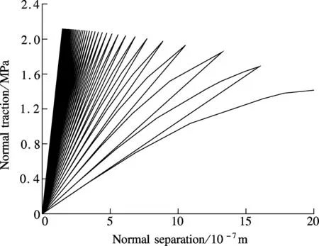
Fig.6 Constitutive relationship of asphalt concrete at the center (r=0.6)
4 Conclusions
1) A fatigue damage evolution model integrated with a bi-linear CZM is employed in this paper to investigate the fatigue properties of asphalt concrete. The model is implemented in the finite element software and then the indirect tensile fatigue test is simulated.
2) Fatigue lives obtained by numerical analysis show good agreement with the laboratory results. It can be concluded that the numerical model developed in this paper can predict the fatigue damage of asphalt concrete.
3) The features of damage accumulation and the process of fatigue failure in IDT are discussed. The results are matched qualitatively with the laboratory results. Fatigue damage accumulates in a nonlinear manner and damage initiation phase is the major part of fatigue failure in IDT. As the stress ratio is increased, the time of steady damage growth stage decreases significantly.
[1]Kim Y R, Little D N, Lytton R L, et al. Fatigue and healing characterization of asphalt mixtures [J].JournalofMaterialsinCivilEngineering, 2003,15(1):75-83.
[2]Lee H J, Daniel J S, Kim Y R. Continuum damage mechanics-based fracture model of asphalt concrete [J].JournalofMaterialsinCivilEngineering, 2000,12(2):105-113.
[3]Kim Y R. Mechanistic fatigue characterization and damage modeling of asphalt mixtures [D]. College Station, TX, USA: Texas A& M University, 2003.
[4]Ghuzlan K A, Carpenter S H. Fatigue damage analysis in asphalt concrete mixtures using the dissipated energy approach [J].CanadianJournalofCivilEngineering, 2006,33(7):890-901.
[5]Barrenblatt G I. The mathematical theory of equilibrium of cracks in brittle fracture [J].AdvancesinAppliedMechanics, 1962,7(3): 55-129.
[6]Dugdale D S. Yielding of steel sheets containing slits[J].JournaloftheMechanicsandPhysicsofSolids, 1960,8(2): 100-104.
[7]Rice J R.Mathematicalanalysisinthemechanicsoffracture:anadvancedtreaties[M]. New York: Academic Press, 1968: 191-311.
[8]Soares J B, Freitas F A C, Allen D H. Crack modeling of asphalt mixtures considering heterogeneity of the material [J].TransportationResearchRecord, 2003,1832: 113-120.
[9]Tvergaard V, Hutchinson J W. The relation between crack growth resistance and fracture process parameters in elastic-plastic solids [J].JournaloftheMechanicsandPhysicsofSolids, 1992,46(6):1377-1397.
[10]Song S H. Fracture of asphalt concrete: a cohesive zone model approach considering viscoelastic effects[D]. Champaign, IL, USA: University of Illinois at Urbana-Champaign, 2006.
[11]Kim H, Wagoner M P, Buttlar W G. Numerical fracture analysis on the specimen size dependency of asphalt concrete using a cohesive softening model [J].ConstructionandBuildingMaterials, 2009,23(5): 2112-2120.
[12]Caro S, Masad E, Bhasin A, et al. Micromechanical modeling of the influence of material properties on moisture-induced damage in asphalt mixtures [J].ConstructionandBuildingMaterials, 2010,24(7): 1184-1192.
[13]Yin Anyi, Yang Xinhua, Yang Zhenjun. 2D and 3D fracture modeling of asphalt mixture with randomly distributed aggregates and embedded cohesive cracks [C]//IUTAMSymposiumonMultiscaleProblemsinStochasticMechanics. Karlsruhe, Germany, 2012: 114-122.
[14]Kim Y R, Allen D, Little D. Computational model to predict fatigue damage behavior of asphalt mixtures under cyclic loading[J].TransportationResearchRecord, 2006,1970: 196-206.
 Journal of Southeast University(English Edition)2013年4期
- Journal of Southeast University(English Edition)的其它文章
- Optimal decision thresholdfor soft decision cooperative spectrum sensing
- Two-level Bregmanized method for image interpolation with graph regularized sparse coding
- Exponential stabilization of distributed parameter switched systems under dwell time constraints
- Direct linear discriminant analysis based on column pivoting QR decomposition and economic SVD
- RBF neural network regression modelbased on fuzzy observations
- Design and analysis of dual-mode structure repetitive control based hybrid current regulation scheme for active power filters
