Design and analysis of dual-mode structure repetitive control based hybrid current regulation scheme for active power filters
Zou Zhixiang Wang Zheng Cheng Ming
(School of Electrical Engineering, Southeast University, Nanjing 210096, China)
With the increasing use of nonlinear loads in power systems and more strict requirements by grid codes, the power quality becomes a critical issue today. The nonlinear loads may cause significant low order harmonics, which will not only increase the power loss in distribution lines but also disturb some sensitive electric equipment. Both the passive and the active power filters (APF) have been proposed to alleviate such low order harmonics[1-3]. Compared with the passive power filters, the APF is considered more attractive due to its high efficiency and controllability[4]. The function of the APF is to generate the out-of-phase harmonics purposely to compensate the existent harmonics in grid. In the past several years, the most important research line for the APF is related with the control schemes, which can effectively improve the performance of the APF system. In fact, the performance of the APF is mainly dependent on the current tracking capability. Many conventional current regulations, such as proportional integral(PI) control[5], hysteresis control[6]and deadbeat control[7], etc. have been applied in the APF system. However, these solutions exhibit some well-known drawbacks[8]and from the investigation of the experimental results, the current tracking capabilities based on these methods are relatively weak.
The repetitive control is another promising current regulation scheme today. Originating from the internal model principle, the repetitive control provides a high-performance solution for the grid current quality applications[9-12]. The periodic disturbance and error can be easily eliminated by using this repetitive controller. Therefore, the repetitive controller can precisely track the reference current with various order harmonics, and it is very suitable for the current control in the APF application. However, the transient performance of the conventional repetitive controller is unsatisfactory for the APF application because the control output values update everyNsample intervals and the error convergence rate is slow.Nis the sampling times in a fundamental cycle. To accelerate the convergence rate, the odd-harmonic repetitive control scheme was proposed[13]. Compared with the conventional repetitive controller, the odd-harmonic repetitive controller updates its output values everyN/2 sample intervals, and the convergence rate is faster. Since the main harmonics in the power electronic system are odd harmonics, the odd-harmonic repetitive control (OHRC) was proposed for the shunt APF in Ref.[14]. In addition to the similar ability of harmonic rejection as the conventional repetitive control, the OHRC is verified to offer better transient performance. However, the OHRC only provides high gains for the odd harmonics but it has less controllability for the even order harmonics. Actually, the power system produces even order harmonics when power converters are employed under some unusual conditions[15-16]. Unlike the OHRC, the dual-mode structure repetitive controller (DMRC) can eliminate both the odd and even harmonics[17]. In addition, the DMRC also updates the control output values everyN/2 sample intervals. Thus, the DMRC can not only improve the performance of grid current control under general current harmonic conditions, but also maintain the fast convergence rate. It should be noted that the dynamic performance of repetitive control is not satisfactory because of the memory cells in the forward channel. Therefore, the repetitive controller is usually improved by integrating a feedback controller[18]. To provide good performance for both the steady-state and the transient operation of the APF, a novel hybrid current controller is proposed in this paper by integrating the deadbeat control and the DMRC. By using the proposed hybrid current controller, not only the advantages of the deadbeat controller, namely the fast transient response and easy digital implementation are maintained, but also the high robustness and accurate current tracking ability are provided.
1 System Description

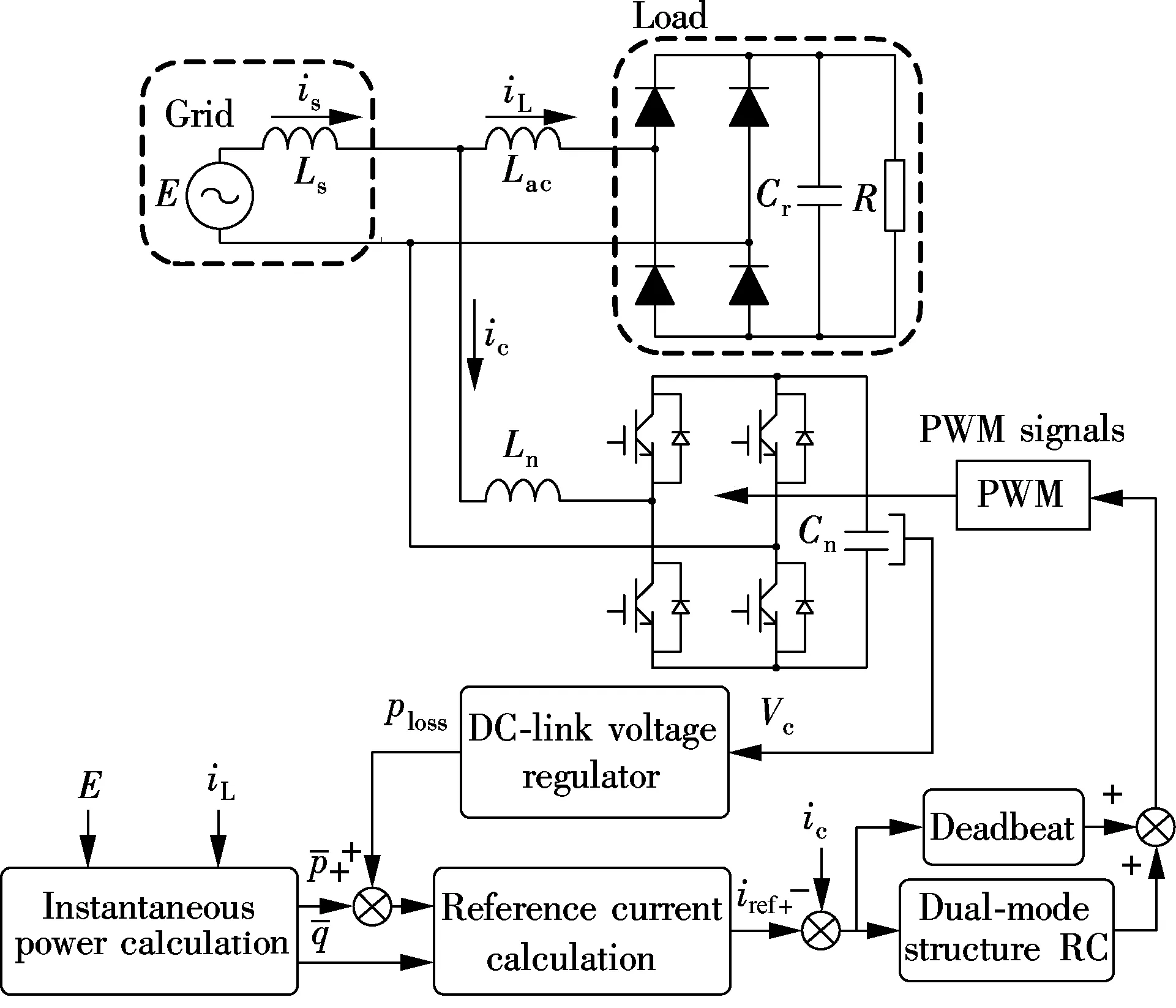
Fig.1 System configuration of the single-phase shunt APF
The dynamics of the APF in Fig.1 can be described as follows:

(1)

(2)
where the compensation currenticand the capacitor voltageVcare the state variables, andVinis the input voltage.S(t) denotes the switching function, and the value is 1 or-1.LnandCnare the values of the grid-side inductor and the DC link capacitor, respectively.
For the operation of the shunt APF, the grid currentisis controlled to track the sinusoidal reference while the DC-link voltage should be kept stable. The cascaded control strategy is proposed to achieve these two control objectives. The current regulation of the shunt APF consists of two parts: One is the current control loop and the other is the reference current generator. The reference current generator is designed based on the instantaneousp-qtheory, which has excellent steady-state performance and can be easily implemented[19]. Unlike the previous current regulation methods, the DMRC and the one-sampling-ahead preview (OSAP) control integrated hybrid current regulation scheme is newly proposed for the APF. Since the focus of this paper is to investigate the performance of harmonic current tracking on the AC side, the standard PI control is used to control the DC link voltage of the APF.
2 Design and Analysis of Proposed Control Scheme
2.1 Design of OSAP controller
Eq.(1) can be described as

(3)
wherekandk+1 represent the sampling instants. The grid voltageEcan be assumed constant in each sampling periodTsby considering the sampling frequency is high enough. The OSAP control algorithm is a standard deadbeat control for the current loop. It yieldsic(k+1)=iref(k) with the transfer function asHcl(z)=z-1. The control law for the current-loop is given as

(4)
2.2 Proposed hybrid current control
The proposed hybrid current control scheme is shown in Fig.2. The DMRC in the proposed hybrid controller has the controllability for both the odd and the even order harmonics. TwoN/2 memory cells run in parallel and the controller updates its control output everyN/2 sample intervals. Therefore, the convergence rate of the DMRC in the hybrid controller is faster than that of the conventional repetitive control schemes. The transfer function of the proposed hybrid controller is given as follows:

(5)
whereGohrc(z),Gehrc(z),Gf(z)=zandGosap(z) are the discrete transfer functions of the OHRC, the even-harmonic repetitive controller (EHRC), the compensation filter and the OSAP controller, respectively.ko≥0 andke≥0 are the repetitive control gains.

Fig.2 Proposed hybrid current control system
In Eq.(5), a low-pass filterQ(z) is employed to enhance the robustness of the system. Particularly, the DMRC will turn into an OHRC or an EHRC whenke=0 orko=0. The DMRC can also be turned into a conventional repetitive controller (CRC) with the repetitive gain ofko+kewhenko=kewith the transfer function as follows:
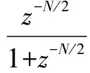
(6)
The open-loop frequency response fromiref(z) toic(z) of the hybrid current controller is given in Fig.3.ko=0.8 andke=0.6 are selected here as the repetitive gains. Obviously, the large gains are available at both the odd and the even order harmonics. Therefore, the proposed hybrid controller can offer a good current tracking capability for both the odd and the even order harmonics. Besides, the phase of the proposed hybrid controllers is zero at the fundamental and the harmonic frequencies by incorporating the phase compensating termGf(z). In order to enhance the robustness of the system,Q(z)=a0z-1+a1+a0zis used, where 2a0+a1=1. It should be mentioned thatQ(z) is a first-order low-pass filter with zero
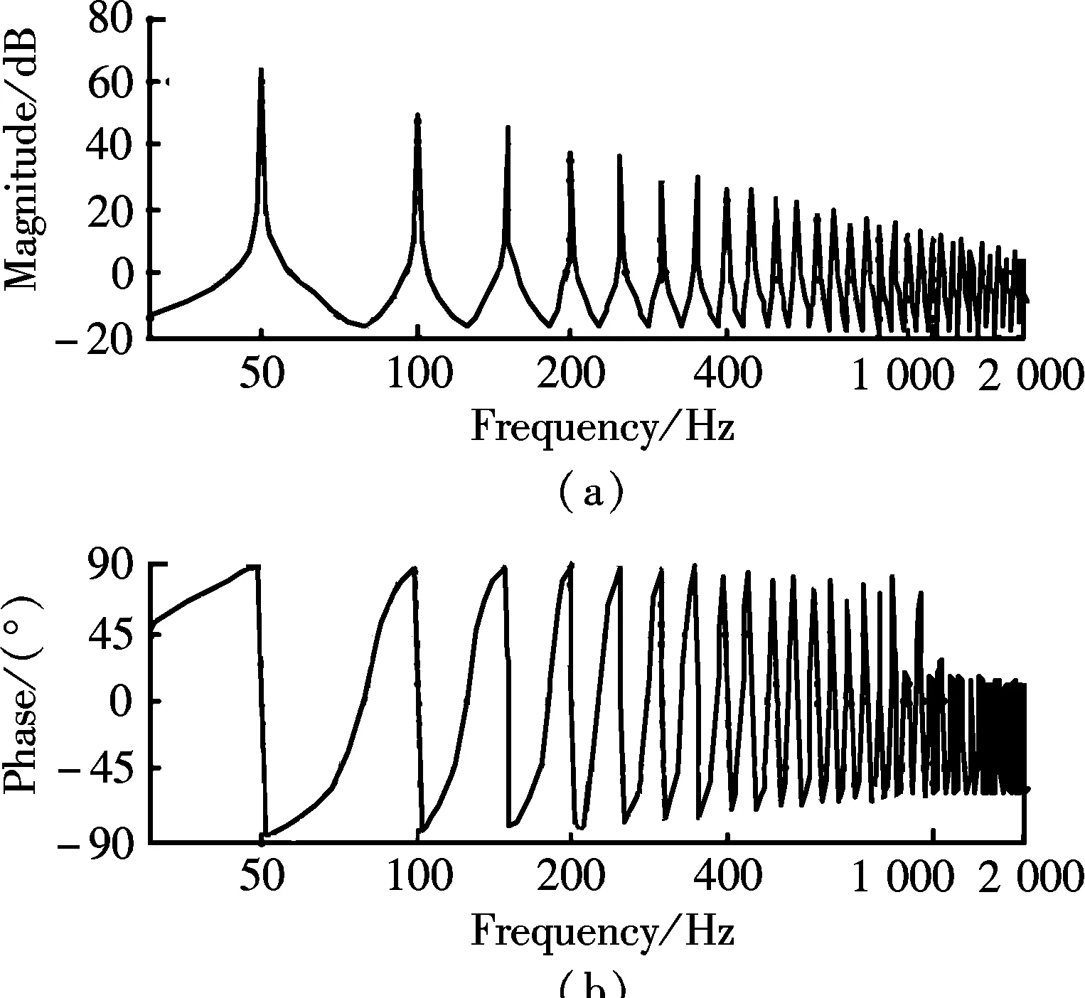
Fig.3 Frequency response of the proposed hybrid controller. (a) Magnitude; (b) Phase
phase shift. With the increase ofa0, the value of ‖1/Q(z)‖ is increased, which will “push” the poles into the unit circle and make the system more stable. However, the gains beyond the cut-off frequency are reduced with the introduction of the filter. Therefore, a tradeoff design should be made between the tracking precision and the system robustness for the low-pass filter.
2.3 Analysis of voltage loop
From a physical point of view, the output of the voltage loopplosscan be seen as the total loss of the APF. Therefore, the DC-link voltage is controlled to be constant in the steady state to minimize the losses, and the PI is used in the DC-link voltage controller. From Eq.(2), the DC-link voltage can be derived as
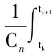
(7)
Obviously, due toS(t), theVc(t) in Eq.(7) is discontinued. Eq.(7) can be averaged in one sample interval as

(8)
where 〈Vc〉Tsrepresents the average value ofVc(t) in a sample interval, andD(t) denotes the duty ratio. Assuming that the APF is in steady-state, the compensation currenticcan be written as

(9)
whereicf(t) andich(t) are the fundamental frequency and harmonic frequencies current components, respectively;ωis the fundamental frequency; andkdenotes thek-th order harmonic. Considering Eq.(8) and Eq.(9), it can be found that the DC-link voltage includes not only the fundamental term but also the harmonic terms, which means both the fundamental and the harmonic components contribute to the oscillation of the DC-link voltage. Practically, only the oscillation is twice that the fundamental frequency when the power exchange between grid and APF is considered. A low-pass filter (LPF) is designed to reduce the effect of the second order harmonic. Fig.4 shows the block diagram of the DC link voltage loop, where the measured voltage is filtered before inputting to the PI controller so that the current inner loop is less affected by the DC-link voltage variation. The cut-off frequency of the LPF is 60 Hz here.Vdc-refis the reference value of the DC-link voltage.

Fig.4 Block diagram of the DC link voltage loop
2.4 Robustness analysis
In practice, the system parameter may fluctuate. The uncertainty of the system parameter can be written as
Lr=Ln+ΔL
(10)
whereLris the real values of the converter-side inductor, and ΔLis the uncertainties of the inductor. Considering the uncertainties of system parameters, the real system transfer function ofHcl(z) becomesHs(z):
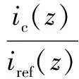
(11)

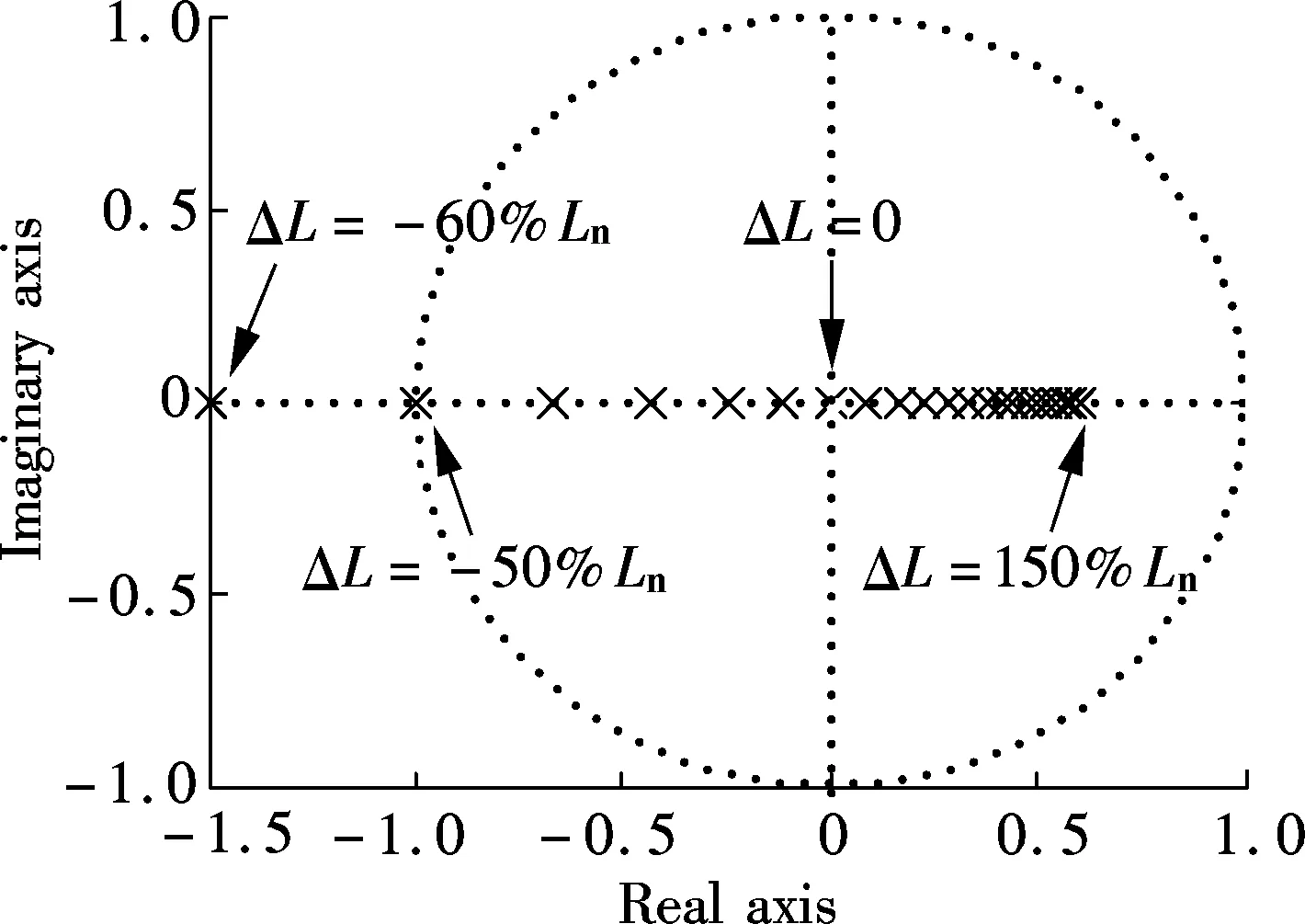
Fig.5 Pole map of the APF system with only OSAP when the parameter fluctuates
2.5 Improvement for suppressing high order harmonics
For the frequency response of the proposed hybrid current controller in Fig.3(a), the gains of harmonics decrease with the increase in the harmonic order. When the harmonic frequency exceeds 1 kHz, the gains at harmonics almost approach zero. In order to eliminate some specific high order harmonics in the APF system, a modified structure of the proposed hybrid controller is proposed with the resonant controller. The zero steady-state error resonant control has been widely used in the synchronous-frame control system in recent years[20-21]. This controller can be summarized as a set of band pass filters, which generate large gains at the selected frequency. The transfer function of resonant control for selective harmonics is illustrated as follows:
(12)
whereωnare the selective harmonic frequencies andknare the control gains. The corresponding structure of the modified controller is shown in Fig.6(a), which incorporates both the DMRC and the resonant controller. The selective harmonic frequencies resonant controller is introduced, which aims to further reduce the selective harmonic contents. The transfer function of the modified controller is given as

(13)
whereGdmrc(s) is the transfer function of the pure DMRC. Referring to Ref.[22], the DMRC term in Eq.(13) can be derived as follows:
(14)
From Eq.(14), it can be seen that the DMRC term can be divided as a PI term and an infinite resonant term. Therefore, the differences between the pure DMRC and the modified structure controller are the control gains of the selective harmonic frequencies. The corresponding control gains change from 4(ko+ke)/(NTs) for the pure DMRC to 4(ko+ke)/(NTs)+knfor the modified controller. Sinceknis not affected by the low-pass filterQ(z), the magnitudes of the selective frequencies can be increased. It is noteworthy that the performance of the whole system can be improved with the increasing number of resonant units, but the computational complexity will also be increased. Fig.6(b) shows the open-loop frequencies response with the introduction of the 15th and
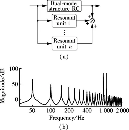
Fig.6 Modified current controller. (a) Block diagram; (b) Open-loop frequency response
the 17th resonant units. It is obviously shown that the gains at the 15th and the 17th harmonic frequencies have been increased effectively.
2.6 Comparative analysis
The CRC-based APF[9]and the OHRC-based APF[14]have already been proposed to improve the power quality. Since these two methods are both internal model principle based control, the corresponding APF can track the periodic reference and reject the disturbance well. However, the shortcomings of these two control schemes for APF are also apparent.
First, the dynamic performance of the CRC-based APF is not good because of theNmemory cells in the feed-forward channel. The CRC updates its output value everyNsample intervals, which means that the control signal will be updated in at least one fundamental cycle. Secondly, the even-harmonic suppression ability of the OHRC-based APF is weak. Since the OHRC is designed only for the odd-harmonic frequency, the even-harmonic can hardly be eliminated by this type of the APF. Therefore, the steady-state performance of the OHRC-based APF is limited. The hybrid control scheme proposed in this paper overcomes the shortcomings of the two methods and achieves good steady-state and dynamic performance.
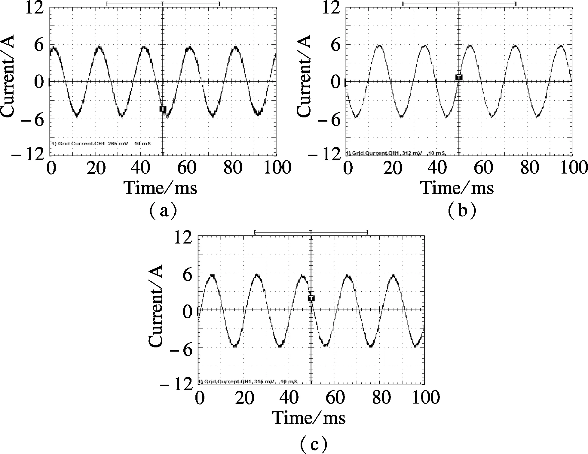
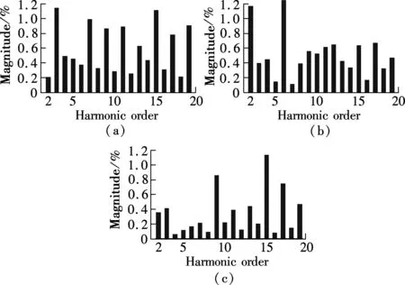
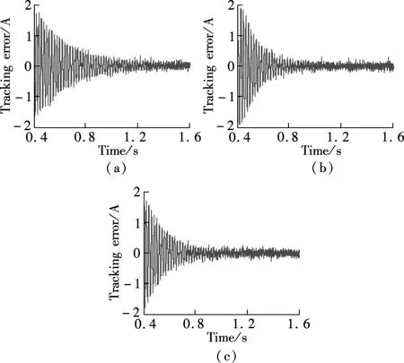
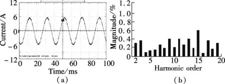
From Refs.[22] and [23], it can be concluded that the CRC and the DMRC have the controllability for DC component, the fundamental component and different order harmonics, while the OHRC can only track for the fundamental component and the odd harmonic signals. For the fundamental and odd-harmonic signals, the tracking performance of the OHRC is better than that of the CRC when the same repetitive gains are employed, namely,ko=kr(kris the repetitive gain of the CRC). This is due to the fact that the equivalent odd-harmonic resonant gains of the OHRC are twice larger than those of the CRC. Meanwhile, the equivalent resonant gains of the DMRC is larger than those of the CRC for all the interesting frequencies whenko+ke=kr. The stability domain of repetitive gainkrfor the CRC is 0 To verify the proposed hybrid current regulation scheme experimentally, the laboratory setup is built and the experiments are carried out. The experimental prototype of the APF is based on a Semikron AN-8005 (an H-bridge IGBT inverter). The system configuration is the same as the system configuration described in Fig.1. The single-phase shunt APF is controlled using a dSPACE DS1104 controller card. The parameters are selected as follows:Vc=100 V,E=65 V,Ln=5 mH,Cn=5500 μF,f=50 Hz,Lac=3 mH, and the switching frequencyfs=10 kHz. The nonlinear load is a full-wave diode rectifier withCr=2200 μF. The reactive power with the nominal resistor is approximately zero. First, Fig.7(a) shows the grid current with OSAP+CRC; Fig.7(b) shows the grid current of OSAP+OHRC; and Fig.7(c) shows the grid current of the hybrid current controller. Fig.8 shows the measured harmonic spectrum of the three schemes. It is observed that the total harmonic distortion(THD) values are 5.88% and 4.63% for OSAP+CRC and OSAP+OHRC, respectively. The value is reduced to 3.35% by using the proposed hybrid controller. Compared with the CRC approach, the steady-state performance is better and the harmonic contents are lower for almost all the interesting Fig.7 Grid current waveform after compensation. (a) OSAP+CRC-controlled APF; (b) OSAP+OHRC-controlled APF; (c) Proposed hybrid-controlled APF Fig.8 Harmonic content of grid current. (a) OSAP+CRC-controlled APF; (b) OSAP+OHRC-controlled APF; (c) Proposed hybrid-controlled APF frequencies. Compared with the OHRC approach, the proposed DMRC-based hybrid controller has superiority in compensation ability since it can suppress not only the odd order but also the even order harmonics. Secondly, Fig.9 shows the measured transient tracking performance of the compensation current with the OSAP+CRC, the OSAP+OHRC, and the proposed hybrid control. In Fig.9(a), the OSAP+CRC starts working att=0.4 s. The tracking error between the reference current and the real current is reduced from 2 to 0.3 A, and the convergence time is about 1s. In Fig.9(b), the OSAP+OHRC controller works att=0.4 s. The corresponding tracking error is reduced from 3 to 0.3 A, and the convergence time is about 0.6s. In Fig.9(c), the hybrid controller begins to work at the same time, and the transient effect is almost the same as that of Fig.9(b). It is obvious that the OSAP+OHRC controller and the proposed hybrid controller have a better convergence rate compared with the OSAP+CRC controller. Fig.9 Tracking error of the compensation current. (a) OSAP+CRC-controlled APF; (b) OSAP+OHRC-controlled APF; (c) The proposed hybrid-controlled APF Finally, Fig.10(a) and Fig.10(b) show the measured grid current with the compensation of the proposed hybrid controller plus the 15th and the 17th order resonant units and the corresponding harmonic content. Compared with Fig.9(c), it is obviously seen that the contents of the Fig.10 Measured grid current using the proposed hybrid control plus 15th and 17th order resonant units. (a) Grid current; (b) Harmonic contents 15th and the 17th order harmonics have been reduced effectively. The THD of the grid current is further suppressed with the introduction of resonant units, and the value is 2.23%. In this paper, a novel hybrid current regulation scheme is proposed for the single-phase shunt APF by integrating the deadbeat control and the DMRC. The all-digital approach can be easily implemented and can also be extended into a three-phase APF system. It not only offers better tracking ability for current harmonics compensation, but also maintains good transient performance. This paper also presents a modified structure, which incorporates the proposed hybrid current controller and the resonant controller, to further suppress some high order specific harmonics. As analyzed in this paper, the DMRC can be regarded as a set of resonant controllers plus a PI term. With the integration of the DMRC and the selective harmonic resonant controller, the control gain at the selective harmonic frequency can be adjusted flexibly. Additionally, the relationships among different repetitive control schemes are also shown. By the experimental results, it is verified that the THD performance of the proposed hybrid controller is better than that of the OHRC+OSAP approach, and its transient performance is better than that of the CRC+OSAP approach. The grid current can achieve good performance and meet the requirements of IEEE 519 quite well. [1]Akagi H. Trends in active power line conditioners [J].IEEETransPowerElectronics, 1994,9(5): 263-268. [2]Fujita H, Akagi H. A practical approach to harmonic compensation in power systems-series connection of passive and active filters [J].IEEETransIndustryApplications, 1991,27(6): 1020-1025. [3]Green T C, Marks J H. Control techniques for active power filters [J].IEEProceedingsofElectricPowerApplications, 2005,152(2): 369-381. [4]Singh B, Al-Haddad K, Chandra A. A review of active filters for power quality improvement [J].IEEETransIndustrialElectronics, 1999,46(5): 960-971. [5]Buso S, Malesani L, Mattavelli P. Comparison of current control techniques for active filter applications [J].IEEETransIndustrialElectronics, 1998,45(5): 722-729. [6]Lin B R, Tsay S C, Liao M S. Integrated power factor compensator based on sliding mode controller [J].IEEProceedingsofElectricPowerApplications, 2001,148(3): 237-244. [7]Nishida K, Rukonuzzman M, Nakaoka M. Advanced current control implementation with robust deadbeat algorithm for shunt single-phase voltage-source type active power filter [J].IEEProceedingsofElectricPowerApplications, 2004,151(3): 283-288. [8]Teodorescu R, Liserre M, Rodríguez P.Gridconvertersforphotovoltaicandwindpowersystems[M]. New Jersey: Wiley, 2011:289-311. [9]Garcia-Cerrada A, Pinzon-Ardila O, Feliu-Batlle V, et al. Application of a repetitive controller for a three-phase active power filter [J].IEEETransPowerElectronics, 2007,22(1): 237-246. [10]Escobar G, Hernandez-Briones P G, Martinez P R, et al. A repetitive-based controller for the compensation of 6l±1 harmonic components [J].IEEETransIndustrialElectronics, 2008,55(4): 3150-3158. [11]Costa-Castelló R, Grino R, Parpal R C, et al. High-performance control of a single-phase shunt active filter [J].IEEETransControlSystemsTechnology, 2009,17(6) 1318-1329. [12]Ramos G A, Costa-Castelló R. Power factor correction and harmonic compensation using second-order odd-harmonic repetitive control [J].IETControlTheory&Applications, 2012,6(11): 1633-1644. [13]Grino R, Costa-Castelló R. Digital repetitive plug-in controller for odd-harmonic periodic references and disturbances [J].Automatica, 2005,41(1): 153-157. [14]Costa-Castelló R, Grino R, Fossas E. Odd-harmonic digital repetitive control of a single-phase current active filter [J].IEEETransPowerElectronics, 2004,19(1): 1060-1068. [15]Buddingh P C. Even harmonic resonance-an unusual problem [J].IEEETransIndustryApplications, 2003,39(1): 1181-1186. [16]Taylor J B. Even harmonics in alternating-current circuits [J].TransactionsoftheAmericanInstituteofElectricalEngineers, 1909, ⅩⅩⅤⅢ(1): 725-732. [17]Zhou K, Wang D, Zhang B, et al. Dual-mode structure digital repetitive control [J].Automatica, 2007,43(3):546-554. [18]Cosner C, Anwar G, Tomizuka M. Plug in repetitive control for industrial robotic manipulators [C]//ProcIEEEIntConfRobotAutomat. Cincinnati, OH, USA, 1990:1970-1975. [19]Superti-Furga G, Todeschini G. Discussion on instantaneous p-q strategies for control of active filters [J].IEEETransPowerElectronics, 2008,23(7): 1945-1955. [20]Liserre M, Teodorescu R, Blaabjerg F. Multiple harmonics control for three-phase grid converter systems with the use of PI-RES current controller in a rotating frame [J].IEEETransPowerElectronics, 2006,21(5): 836-841. [21]Lascu C, Asiminoaei L, Boldea I, et al. High performance current controller for selective harmonic compensation in active power filters [J].IEEETransPowerElectronics, 2007,22(9): 1826-1835. [22]Zou Z, Wang Z, Cheng M. Design and analysis of operating strategies for a generalised voltage-source power supply based on internal model principle [J/OL].IETPowerElectronics. (2013-08-21)[2013-10-09].http://digital-library.theiet.org/content/journals/10.1049/iet-pel.2013.0159. [23]Zou Z, Wang Z, Cheng M. Modeling, analysis, and design of multi-function grid-interfaced inverters with output LCL filter [J/OL].IEEETransPowerElectronics. (2013-09-04)[2013-10-09]. http://ieeexplore.ieee.org/xpls/abs_all.jsp?arnumber=6588968&tag=1.3 Experimental Verification
4 Conclusion
 Journal of Southeast University(English Edition)2013年4期
- Journal of Southeast University(English Edition)的其它文章
- Optimal decision thresholdfor soft decision cooperative spectrum sensing
- Two-level Bregmanized method for image interpolation with graph regularized sparse coding
- Exponential stabilization of distributed parameter switched systems under dwell time constraints
- Direct linear discriminant analysis based on column pivoting QR decomposition and economic SVD
- RBF neural network regression modelbased on fuzzy observations
- Aerodynamics of flexible wing in bees’ hovering flight
