EXPERIMENTAL STUDY OF HTC FOR FILM COOLING OF PARALLEL-INLET HOLES
Yang Weihua,Zhang Jingzhou
(College of Energy and Power Engineering,Nanjing University of Aeronautics and Astronautics,Nanjing,210016,P.R.China)
INTRODUCTION
Film cooling method is widely used to cool hot gas path components,such as combustion chamber wall and turbine blade in modern gas turbine,etc.Coolant air from the compressor produces a film layer to prevent walls from the detrimental effects of hot combustion gases.In order to extend the lifeof gas turbine,it is essential to improve cooling designation methods for keeping the stable temperature level and thermal gradients in various turbine components within the limitation of acceptation by means of theminimum cooling air.
The importance of film cooling has been studied using experimental,analytical and computational methods[1-4].Refs.[5-12]studied the film cooling performance with cylindrical injection holes,and discussed theinfluences of blowing ratio,main flow turbulenceintensity or density ratio on heat transfer coefficient(HTC)or adiabatic film cooling effectiveness distribution by varying hole aperture to length ratio,compound angle or interval between injection holes/rows.Refs.[13-14]studied the film cooling effectiveness of onerow discrete holes and found that the cooling effectiveness increases with the velocity ratio and the density ratio.However,the influence of velocity,density,geometrical parameters and their interactions are too complicated to clearly understand.Ref.[15]studied the heat transfer characteristics of two-dimensional slot and found that convective coefficient of thefilm cooling along the flow direction on the cooled plate could be divided into three regions.In the first and third regions,convective coefficient is decreased along flow direction and in the second region,it is increased along flow direction.Refs.[16-17]studied the influence of blowing ratio and geometrical parameters of one-row film hole on the cooling effectiveness of cooled plate.They found that the geometrical parameters had a great influence on the cooling effectiveness of film cooling and cooling effectiveness was decreased with the increase of the blowing ratio.Ref.[18]studied the film cooling effectiveness in machined ring liners with the mass-transfer analogy method.Designation of experiment is adopted to investigate how the effec-tiveness is influenced by coolant injection angle,shape of the slot lip(straight/tapered),shape of the slot exit,and thickness of the slot lip.On the basis of experiments,an accurate data-correlation equation is obtained.Ref.[19]measured thetemperatures of gas phase and adiabatic wall downstream of theinjection slot,and obtained thetemperature profiles in the mixing layer as well as film cooling effectiveness correlation.Refs.[20-21]found that compound angle injection results in higher film cooling effectiveness compared with stream-wiseinjection at a given momentum ratio.However,the heat transfer rates aresubstantially enhanced due to increased jet cross-flow interaction.Therefore,the overall performance combining the effects of reducing blade temperature and heat transfer was flower for compound angle holes.These findings have been confirmed by Refs.[22-23].Ref.[24]studied the effects of blowing ratio and turbulence level on the heat transfer characteristics of a wall jet in a cocurrent stream.The results showed that the turbulence level had agreat influence on the heat transfer for the wall jet when the blowing ratio m<1,and both the adiabatic wall temperature and the relative heat transfer function should be considered when calculating heat transfer.But when m>1,the turbulence level has no effect on heat transfer.
As mentioned above,it can be seen that most of theinvestigations havebeen performed the heat transfer characteristics of the film cooling in terms of the inclined angle injection of holes.Especially,they are only limited to the one-row discrete hole or the slot.Therefore,it is not clearly for the paralleled injection of the film hole.In this paper,thecooling characteristics of one-row,two-row and three-row film holes are experimentally investigated.Experimental results can provide the reference value for designation of combustion chamber.
1 EXPERIMENTAL APPARATUS
All experiments areperformed in a low speed wind tunnel setup with compressing air supply to keep the mainstream and the coolant air.Fig.1 shows the comprehensive process of the experimental arrangements.Firstly,environment temperature air from the compressor is drawn through the orifice flow meter.Then,it is divided into two branches of the streams:One is the mainstream air and the other is the coolant stream air.The accuracy of the orifice flow meter is 1.0%.Mainstream air is heated up to 80°C by two sets of the 60 k W heaters,which is monitored by a T-type thermocouple.Then,it passes through a section with baffles to ensure adequate mixing of hot air to obtain a uniform temperature across the cross-sections and the coolant stream passes through a LBZ type buoyage flow meter,which is used to measure the mass flow rate controlled by a gatevalve.Accuracy of the LBZ type buoyage flow meter and the T-type thermocouple is 1.0% and 0.75%. Coolant stream passes through film cooling holes to form a film layer on the surface of the test plate.Temperature of the test wall is measured by infrared the rmography system(TVS-2000 MK)with accuracy and measured temperature range of± 1°C(0— 100°C).All the measured data of temperature are connected with 8-channel HP34970A data collection system.
Test sections(Fig.2)is a rectangular channel with 383 mm(length)× 200 mm(width)×87 mm(height)dimensions.The 0.1 mm thick test plate is made of stainless steel plate with 200 mm×200 mm(length and width)dimensions.Surface of the test plate is painted with high temperature black paint to assure a uniform measure emissivity of 0.96.Three T-type thermocouples to act as reference for the infrared the rmograph system are fastened on the rear of the test wall with 502 glue.Eq.(1)shows the relationship between the corrected infrared temperature and the thermocouple date,where T0 is the infrared the rmograph temperature and T the corrected infrared temperature.
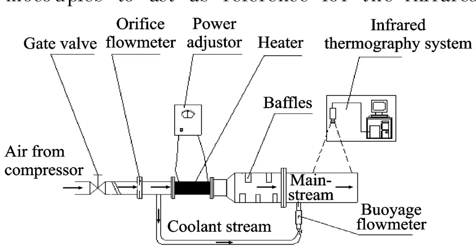
Fig.1 Experimental setup
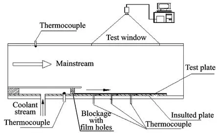
Fig.2 Schematic of test section

The insulated plate is made of a 1-inch(1 inch≐2.54 cm)thick Kaowool board thermal ceramics,which has a very low thermal conductivity of 0.06 W/mK.A T-type thermocouple is glued on the outer surface of the insulated plate.Depending on experimental conditions,this temperature is between 25.0°C and 25.5°C,while ambient temperature is approximately 24°C.Difference between ambient temperature and outer surface temperature of insulated plate is less than 1.5 K.Therefore,the convection and the radiation losses from insulate plate are not considered.
The thick Bakelite slab of machine-made film holes is set to W=3 mm,and the length,width and height of the Bakelite slab are set to 200,3,10 mm,respectively.As shown in Fig.3,they have three patterns: one-row,two-row with aligned-arrangement and staggered-arrangement ways and three-row.Each arrangement has different diameters.The geometrical dimension of test pieces is seen in Table 1,where X is the ratio of holing on blackage.
Uncertainty of the experiment arises from the measurement deviation of temperature of mainstream,coolant stream and test wall,pressure of mainstream and coolant stream,and diameter of film hole,respectively.Estimated uncer-
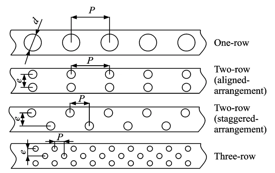
Fig.3 Arrangement paterns of film holes
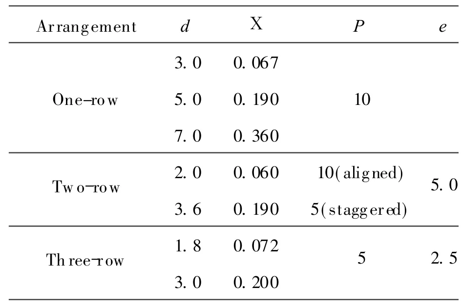
Table 1 Dimension of test pieces for each arrangement
tainty of mainstream temperature is determined forΔT∞= ± 0.6°C,coolant stream temperature isΔT2= ±0.2°C and hole diameter isΔd=0.01 mm.The accuracy of infrared camera system is± 1.5°C(0— 100°C).The uncertainty of HTCis obtained by±8.2% using the method in Ref.[25].
2 DEFINITIONSOF FILM COOLING PARAMETERS
2.1 Blowing ratio
The blowing ratio is defined as

It can be rewritten as

where A c,A m are the flow cross-section areas of coolant stream and mainstream,respectively,◦m,c◦m the mass flow rate of coolant stream and main m stream,respectively.
Let A m/A equal to 7.7 and substituted into Eq.(3),we get

The value of X for each arrangement is showed in Table 1.
2.2 Heat transf er coef ficient
HTCof film cooling over the cooled plate defined in Ref.[26]is

where q=(UI/A)is the heat flow rate of wall,U,I and A are the electric current,voltage and heat area of wall,respectively. The adiabatic wall temperature T aw represents the surface temperature of a perfectly insulated wall.It can be measured by an infrared the rmograph system when the test plate is not heated.The test plate temperature T w is measured by an infrared the rmograph system when the test plate is heated.
To determine HTC for these models,two tests are conducted for each experimental condition.The heated and the adiabatic surface temperatures are all measured by infrared the rmograph system.The temperature map from infrared the rmograph is shown in Fig.4.There are three analysis lines for calculating the temperature of the test plate on the map.It is measured that at a given x-location the temperature of the plate on the analysis lines does not vary by more than 1— 2°C.Therefore,this experiment validates the 2-D flow pattern of the slot film cooling,and temperature used to calculate HTC at a given x-location is an average of the temperatures on th ree analysis lines.
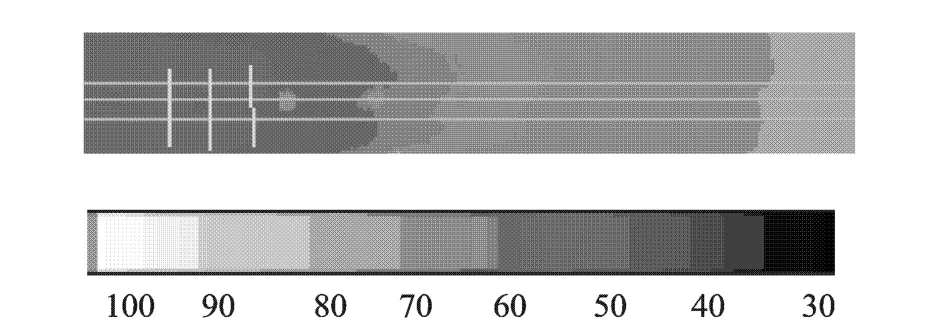
Fig.4 Temperature map of infrared the rmograph
3 RESULTSAND DISCUSSION
3.1 Effects of blowing ratio
Fig.5 gives the effect of blowing ratio on HTC of one-row film hole with different diameters of 3.0,5.0,7.0 mm,respectively.As we can see from Fig.5(a)that the distributions of HTC can be divided into three regions of I,IIand III along flow direction.The region Iis the core region of coolant jet from the film holes.The cooling film does not mix with mainstream air,and heat transfer process directly happens between cooling film and heated wall.Therefore,the heat transfer characteristics between the cooling film and the test plate are analogous to the slot jet heat transfer on the plate,and HTC is significantly decreased with the increase of X/S,where X is the distance between the best position and film holes,and S theheight of Bakelite slab.In the region II,the interaction between mainstream and cooling film is increased with the increase of X/S,and the mixing between the cooling film and mainstream is strengthened with the increase of X/S.The striking of mixing cooling film against the test plate is gradually strengthened,which results in HTC increasing with the increase of X/S.In theregion III,thereis no evident difference between cooling film and mainstream.HTC of film cooling is similar to the common convective heat transfer around an even plate and it is decreased with the increase of X/S.With the increase of blowing ratio,the jet from film holes forms a more stable cooling film on the test plate,and it is more difficult for the cooling film to mix with mainstream.The stable film can weaken the film striking against the test plate,therefore,HTCof film cooling is decreased with the increase of blowing ratio.
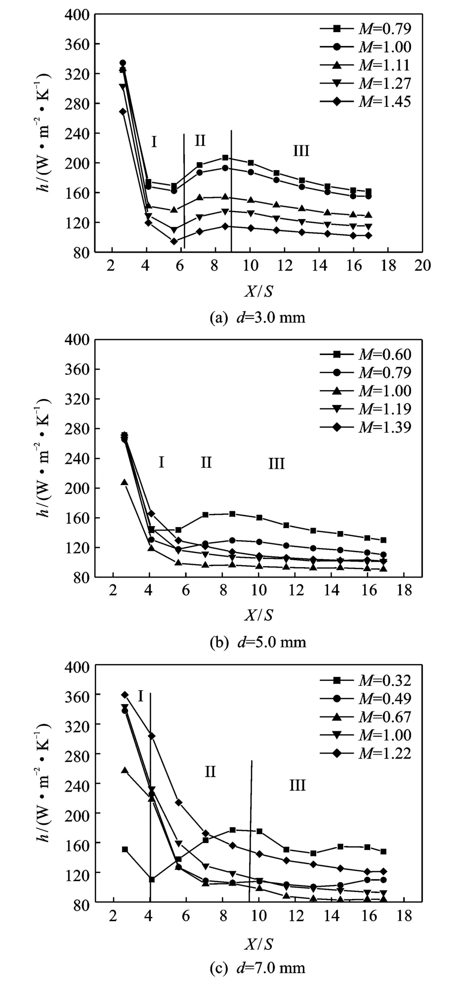
Fig.5 HTCdistributions of one-row film holes
As seen from Fig.5(b),at lower blowing ratio of M=0.79 and 0.60,distributions of HTC are also divided into three regions of I,IIand III,similar to Fig.5(a).But,with regard to the larger blowing ratios,M=1.0,1.19 and 1.39,the coolant jets possess stronger momentum resulting in higher interaction between coolant air and mainstream air nearby the exit of film holes.Therefore,there are not three evident regions for HTCin the direction of flow.In the whole region of heat transfer,HTC of film cooling has a character of convective heat transfer around an even plate.Near the exit of film hole,HTC is rapidly decreased with the increase of X/S.When X/S>6.5,the decrease of HTC is slight.Fig.5(c)shows that the distributions of HTCare similar to those of Fig.5(b).However,for d=3.0 mm,the blowing ratio M resulting in three regions are from 0.79 to 1.45,for d=5.0 mm,M=0.60 and 0.79,and for d=7.0 mm,M=0.32.Therefore,we can draw a conclusion that the blowing ratio resulting in three regions is decreased with the increase of diameter of film hole.
Fig.6 shows the effect of blowing ratios on HTC of two-row film holes with aligned arrangement and staggered arrangement,respectively.As seen from Fig.6(a),at the same heated wall position,HTC is decreased with the increase of blowing ratio.But,the effect of blowing ratio is not evident for the blowing ratio from 0.85 to 1.0.HTCis also divided into three regions on the heated wall and region IIis gradually disappeared with the increaseof blowing ratio.For Fig.6(b),there is a significant decrement of HTC for blowing ratio from 0.59 to 0.82.When M=1.03,the reis not region IIfor HTCon the heated wall,and the heat transfer characteristics of film cooling on the heated wall are similar to the convective heat transfer around a flat.
Fig.7 shows the effect of blowing ratio on HTC of three-row film holes.The characteristics of heat transfer are also similar to those of two-row and one-row.But the blowing ratio resulting in the disappearance of region IIis equal to 1.3.
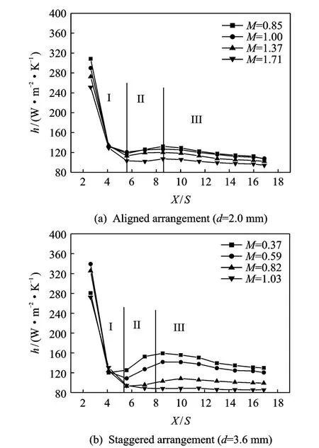
Fig.6 HTC distributions of two-row film holes
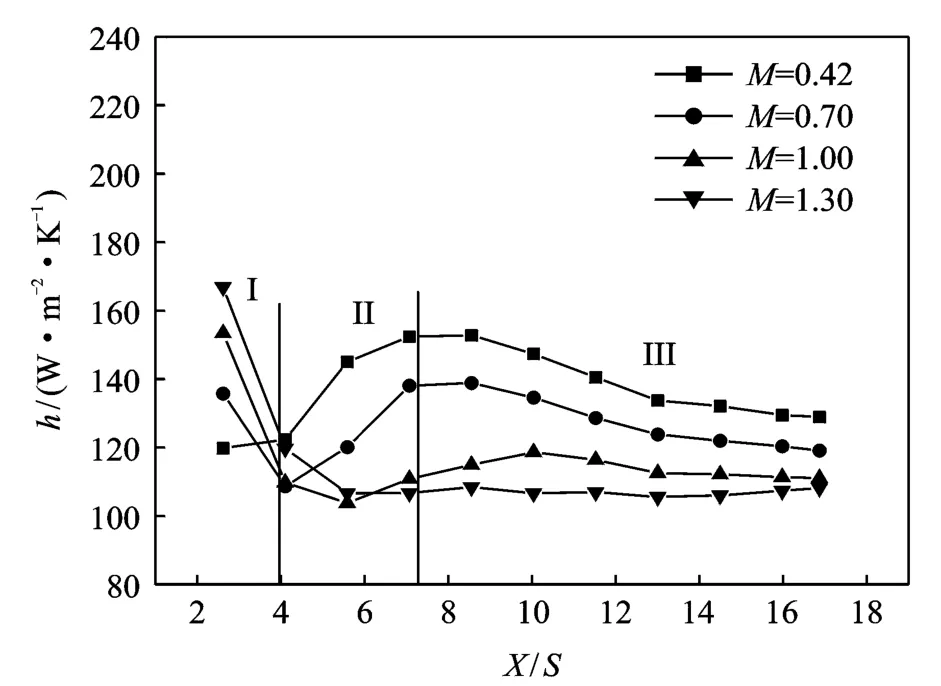
Fig.7 HTCdistributions of three-row film holes(d=3.0 mm)
3.2 Effects of f ilm hole diameter
Fig.8 shows the effects of film cooling hole diameters on HTCunder the condition of blowing ratio M=1.0,respectively. As seen from Fig.8(a),when the blowing ratio is a constant,the coolant jet from the larger film holes can form a more stable cooling film on the test plate than smaller film holes,and the stable cooling film weakens the cooling film striking against the test plate.Therefore,HTC is decreased with the diameter increment from 3.0 mm to 5.0 mm.In Fig.8(b),both aligned and staggered arrangements show a similar decreasing tendency with the diameter increase of film hole.In Fig.8(c),the effect of film hole diameter also has a similar tendency.
3.3 Effects of f ilm hole arrangement
Fig.9 shows the comparison of HTC with different test pieces with M=1 and X=0.2.Obviously,the distribution of HTC along the test plateis different for the four kinds of test pieces.When X/S<5,HTCof three-row is smallest in the four test pieces,but when X/S>5,HTC of two-row(staggered arrangement)is smaller than the other test pieces.When the radiation of high temperature mainstream to the heated wall is neglected,a smaller HTC of film cooling can increase the film cooling effectiveness.Therefore,
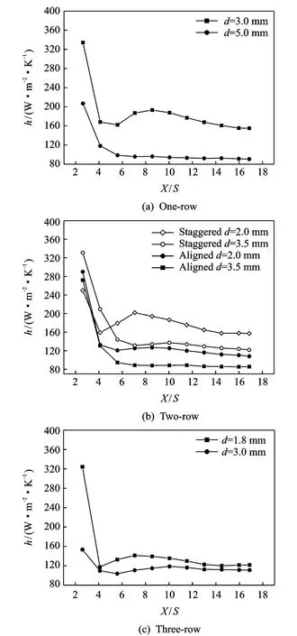
Fig.8 Effects of film cooling hole diameters on HTC
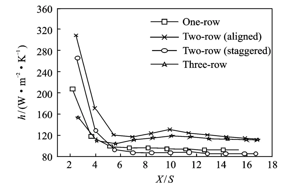
Fig.9 Comparison of HTC with different test pieces(M=1.0,X=0.2)
the film cooling effectiveness of the test piece with three-row film holes is better than that of the other test pieces within the region of W/S<5 on the heated wall,but the effectiveness with two-row film holes(staggered arrangement)is best in the four kinds of test pieces when W/S>5 on the heated wall.
4 CONCLUSIONS
The convective heat transfer characteristics of film cooling with different film hole arrangements are investigated and the following conclusions are drawn:
(1)In the direction of flow with a certain range of blowing ratio,HTC can be divided into three regions and decreased as blowing ratio increases.
(2)HTCof film cooling is similar to theconvection heat transfer around a flat and decreased with the increase of diameter for all kinds of arrangement patterns of film hole.
(3)For the two-row film holes,HTCcan be considered as a condition of the staggered arrangement and it is higher than that of aligned arrangement at the same position on the heated wall.
(4)Three-row film holes have the smallest HTCon the heated wall when X/S<5,but when X/S>5,HTC of two-row ones(staggered arrangement)is the smallest.
[1] Sinha A K,Bogard D G,Crawford M E.Film-cooling effectiveness downstream of a single row of holes with variable density ratio[J].ASM E Jof Turbomachinery,1991,113(3):442-449.
[2] Han J C,Mehendale A B.Flat-plate film cooling with steam injection through one row and two rows of inclined holes[J].ASME Jof Turbomachinery,1986,108(1):137-144.
[3] Yuen C H N,Martinez R F.Film cooling characteristics of rows of round holes at various streamwise angles in a crossflow:Part I.Effectiveness[J].International Jof Heat and Mass Transfer,2005,48(23):4995-5016.
[4] Yuen C H N,Martinez R F.Film cooling characteristics of rows of round holes at various streamwise angles in a crossflow:Part II.HTCs[J].International J of Heat and Mass Transfer,2005,48(24):5017-5035.
[5] Marc D P,Michael C J,David G B.Three component velocity field measurements in the stagnation region of a film cooled turbine vane[J].Journal of Turbomachinery,2002,124(3):445-452.
[6] Jia R G,Bengt S,Petre M,et al.A numerical and experimental investigation of the slot film-cooling jet with various angles[J].Journal of Turbomachinery,2005,127(3):635-645.
[7] Bernsdort S,Rose M G,Abhari R S.Modeling of film cooling-part I: Experimental study of flow structure[J].Journal of Turbomachinery,2006,128(1):141-149.
[8] Xiao Yang,Tang Hongwu.Numerical simulation of a horizontal momentum jet in cross-flow[J].Journal of Hydrodynamics:Ser B,2006,18(1):118-125.
[9] Liu Xiaobing,Zeng Yongzhong,Cao Shuyou.Numerical prediction of vortex flow in hydraulic turbine draft tube for LES[J].Journal of Hydrodynamics:Ser B,2005,17(4):448-454.
[10]Fan Jingyu,Wang Daozeng,Zhang Yan.Three-dimensional mean and turbulence characteristics of an impinging density jet in a confined crossflow in near field[J].Journal of Hydrodynamics:Ser B,2004,16(6):737-742.
[11]Hoda A,Acharya S.Predictions of a film coolant jet in crossflow with different turbulence models[J].Journal of Turbomachinery,2000,122(3):558-569.
[12]Bohn D E,Kusterer K A.Aerothermal investigations of mixing flow phenomenain caseof radially inclined ejection holes at the leading edge[J].Journal of Turbomachinery,2000,122(2):334-339.
[13]Yuen C H N,Martinez-Botas R F.Film cooling characteristics of a single round hole at various streamwise angles in acrossflow:part I effectiveness[J].Int J Heat Mass Transfer,2003,46(2):221-235.
[14]Azzi A,Jubran B S.Numerical modelling of film cooling from converging slot hole[J]. Heat Mass Transfer,2007,43(2):381-388.
[15]Ge SY,Liu D Y,Li JZ,et al.Film cooling[M].Beijing:Science Press,1985.(in Chinese)
[16]Sturgess G J.Design of combustor xiiling slot for high film effectiveness: Part I—Film general development[R].ASME 85-GT-35,1985.
[17]Sturgess G J.Design of combustor xiiling slot for high film effectiveness: Part II—Film initial region[R].ASME 85-GT-36,1985.
[18]Li SC,Mongia H C.Animproved method for correlation of film cooling effectiveness of gas turbine combustor liners[R].AIAA 98-3268,1998.
[19]Cruz C A,Marshall A W.Surface and gas-phase temperatures near a film cooled wall[R].AIAA 2004-3654,2004.
[20]Schmidt D L,Sen B,Bogard D G.Film cooling with compound angle holes:adiabatic effectiveness[J].ASME Journal of Turbomachinery,1996,118(6):807-813.
[21]Sen B,Schmidt D L,Bogard D G.Film cooling with compound angle holes: heat transfer[J].ASM E Journal of Turbomachinery,1996,118(6):800-806.
[22]Ekkad SV,Zapata D,Han J C.Film effectiveness over a flat surface with air and CO2 injection through compound angle holes using a transient liquid crystal image method[J].ASME Journal of Turbomachinery,1997,119(4):587-593.
[23]Ekkad S V,Zapata D,Han J C.HTCs over a flat surface with air and CO2injection through compound angle holes using a transient liquid crystal image method[J].ASME Journal of Turbomachinery,1997,119(4):580-586.
[24]Cho H H,Goldstein R J.Heat(mass)transfer and film cooling effectiveness with injection through discrete holes: Part II—On the exposed surface[J].ASME Journal of Turbomachinery,1995,117(3):451-460.
[25]Holman J P.Experimental methods for engineerings[M].4th Ed.New York:Mc Graw-hill,1984.
[26]Maiteh B Y,Jubran B A.Influence of mainstream flow history on film cooling and heat transfer from two rows of simple and compound angle holes in combination[J].Int J of Heat and Mass Transfer,1999,20(1):158-165.
 Transactions of Nanjing University of Aeronautics and Astronautics2012年1期
- Transactions of Nanjing University of Aeronautics and Astronautics的其它文章
- GRIDLESSMETHOD FOR UNSTEADY VISCOUSFLOWS
- NOVEL WEIGHTED LEAST SQUARESSUPPORT VECTOR REGRESSION FOR THRUST ESTIMATION ON PERFORMANCE DETERIORATION OF AERO-ENGINE
- APPLICATION OF HYBRID AERO-ENGINE MODEL FOR INTEGRATED FLIGHT/PROPULSION OPTIMAL CONTROL
- LINEAR ULTRASONIC MOTOR USING LONGITUDINAL VIBRATION
- VIBRATION CHARACTERISTIC INVESTIGATION OF COUNTER-ROTATING DUAL-ROTOR IN AERO-ENGINE
- CNC SYSTEM OF FLEXIBLE FIXTURE IN AIRCRAFT COMPONENT MANUFACTURING AND ASSEMBLY
