FSKModulation Scheme for High-Speed Optical Transmission
Nan Chi, Wuliang Fang, Yufeng Shao, Junwen Zhang, and Li Tao
(State Key Lab of ASIC System, and Department of Communication Science and Engineering, Fudan University, Shanghai 200433, China)
Abstract In this paper,we describe the generation,detection,and performance of frequency-shift keying(FSK)for high-speed optical transmission and label switching.A non-return-to-zero(NRZ)FSK signal is generated by using two continuous-wave(CW)lasers,one Mach-Zehnder modulator(MZM),and one Mach-Zehnder delay interferometer(MZDI).An RZ-FSK signal is generated by cascading a dual-arm MZM,which is driven by a sinusoidal voltage at half the bit rate.Demodulation can be achieved on 1 bit rate through one MZDIor an array waveguide grating(AWG)demultiplexer with balanced detection.We perform numerical simulation on two types of frequency modulation schemes using MZM or PM,and we determine the effect of frequency tone spacing(FTS)on the generated FSK signal.In the proposed scheme,a novel frequency modulation format has transmission advantages compared with traditional modulation formats such as RZ and differential phase-shift keying(DPSK),under varying dispersion management.The performance of an RZ-FSK signal in a 4×40 Gb/s WDM transmission system is discussed.We experiment on transparent wavelength conversion based on four-wave mixing(FWM)in a semiconductor optical amplifier(SOA)and in a highly nonlinear dispersion shifted fiber(HNDSF)for a 40 Gb/s RZ-FSK signal.The feasibility of all-optical signal processing of a high-speed RZ-FSK signal is confirmed.We also determine the receiver power penalty for the RZ-FSK signal after a 100 km standard single-mode fiber(SMF)transmission link with matching dispersion compensating fiber(DCF),under the post-compensation management scheme.Because the frequency modulation format is orthogonal to intensity modulation and vector modulation(polarization shift keying),it can be used in the context of the combined modulation format to decrease the data rate or enhance the symbol rate.It can also be used in orthogonal label-switching as the modulation format for the payload or the label.As an example,we propose a simple orthogonal optical label switching technique based on 40 Gb/s FSK payload and 2.5 Gb/s intensity modulated(IM)label.
Keyw ords optical communication;return-to-zero frequency shift keying;Mach-Zehnder modulator;Mach-Zehnder delay interferometer;chromatic dispersion;wavelength conversion;label switching
1 Introduction
A dvanced modulation formats increase the tolerance of optical signals to chromatic dispersion and fiber nonlinearity,and they lessen the need for greater bandwidth in electricalcircuits[1]-[7].In many modulation formats,frequency-shift keying(FSK)enables differential detection.Simulations have shown that FSKhas a comparable optical-to-signal noise ratio(OSNR)sensitivity to differential phase-shift keying(DPSK)in a 10 Gb/s transmission system[6].Orthogonal modulation of amplitude-shift keying(ASK)and FSKhas recently attracted much attention for its high-spectral efficiency[7]-[11].One example is the combination of ASKand FSK,FSKcan be used for payload or label modulation in the orthogonal optical label-switching schemes[12]-[15].FSK is a potential solution for future high-speed transmission systems and optical packet switching networks.An FSK signal can be generated by directly modulating electric current in a laser light source.This idea,however,is limited by the relatively low frequency modulation response of the laser and has a detrimental effect of parasitic intensity modulation.In[15],a scheme is proposed to generate high-speed FSK signals at 40 Gb/s.This scheme uses an LiNb O3 external FSK modulator with a complicated design.We previously proposed using FSK signals in 40 Gb/s applications and showed the power penalty after 50 km SMFtransmission is 0.8 d B.We speculated on a novel scheme for generating and detecting return-to-zero FSK(RZ-FSK)signals for 40 Gb/s transmission.
In this paper,we detail the scheme for generating RZ-FSK signals that have a bit rate of 40 Gb/s or higher.In section 2,the RZ-FSKtransmitter and receiver configuration is described,and the principles of RZ-FSK generation and detection are given.
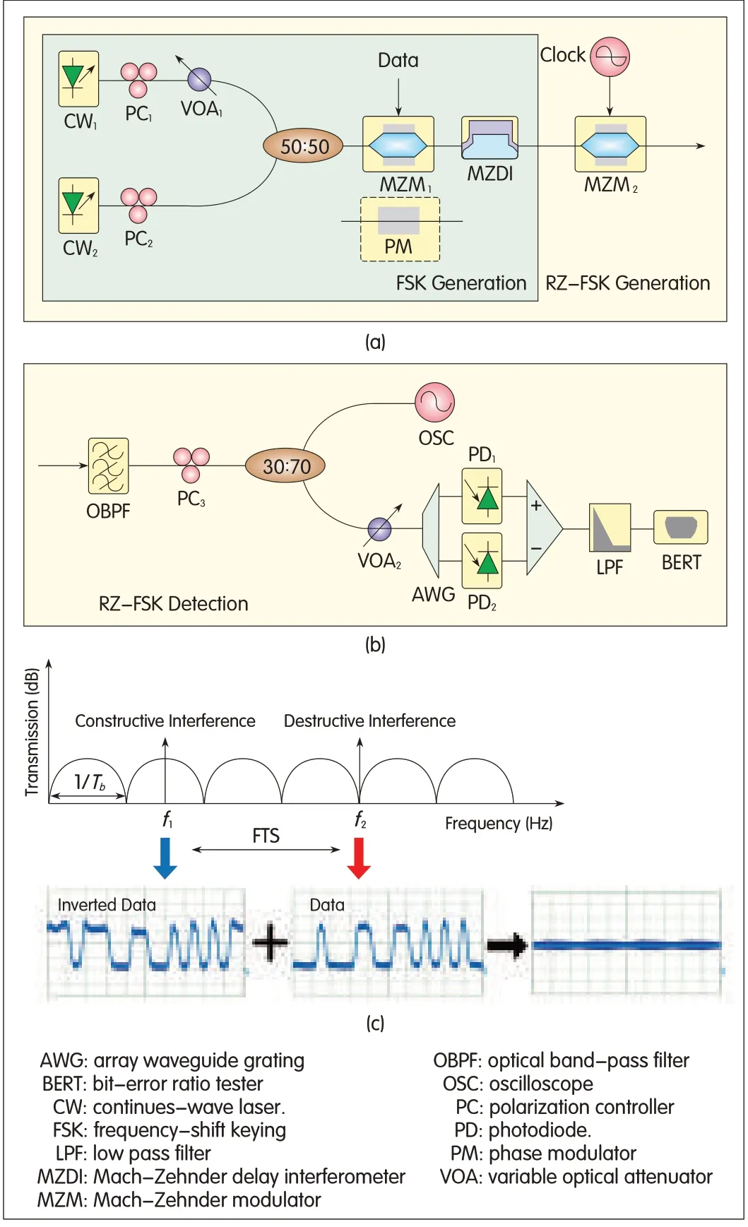
▲Figure 1.Principle of RZ-FSKgeneration and detection and the generated FSKsignal by experiment.(a)Configuration of our proposed transmitter,(b)configuration of the used receiver,(c)measured FSK waveforms of the two tones.
In section 3,we use simulations to compare FSK,DPSK,and RZ-FSK at 40 Gb/s for 12 spans of 80 km SMF.RZ-FSK is more tolerant to nonlinearity and chromatic dispersion than the other modulation formats.We also analyze an RZ-FSK signal in a 4×40 Gb/s WDM transmission system.In section 4,we experiment with a 40 Gb/s RZ-FSK signal over 100 km SMFwith full dispersion compensation.We compare transparent wavelength conversion based on four-wave mixing(FWM)in a semiconductor optical amplifier(SOA)with transparent wavelength conversion based on FWM in a highly nonlinear dispersion-shifted fiber(HNDSF).The feasibility of all-optical signal processing of a 40 Gb/s RZ-FSK signal is validated.In section 5,we discuss the use of the RZ-FSK generation method in a high-speed label switching system.Section 6 concludes the paper.
2 RZ-FSK Transmitter and Receiver
Fig.1(a)shows the schematic of the RZ-FSKtransmitter,and Fig.1(b)shows the schematic of the RZ-FSK receiver.A low-speed RZ-FSK signal can be produced by directly modulating distributed feedback(DFB)lasers.The lasers are driven by a bias current far above threshold,and a relatively small modulation current is added.To generate an FSK signal at 40 Gb/s and above,two continuous-wave(CW)lasers with carefully selected center frequency are combined by a 3 d B coupler and fed into the Mach-Zehnder modulator(MZM1)or phase modulator(PM).The combined input is modulated by NRZdata and then demodulated to intensity modulation by a Mach-Zehnder delay interferometer(MZDI).The MZDIis imbalanced by the introduction of a one-bit time-delay line.The wavelengths of the two beams are carefully selected so that one beam is at the maximum transmission of the MZDI(constructive interference)and the other is at the minimum transmission of the MZDI(destructive interference).Thus,the frequency tone spacing(FTS)isHz,where N=1,2,3,...,n and Tbis a bit period.The center frequencies of the two beams are f1and f2.The optical field exiting a phase modulator for f1is given by

whereΦ1andΦ2are the phases of the neighboring bits,and the data information is reflected in the phase differenceφ.The f1center frequency is given by

However,in a realtransmitter,the rise and falltime of the input signal needs to be taken into consideration.If 1/f1=Tb/m(m=0,1,2,3,...,M),then Tb/M must be greater than the rise time of the input-signalpulse width.If Tb/m is too small,the phase information generated by the MZM1 or PM could not be transferred to the intensity signal in the MZDI.Even if the phase information is accurately transferred to the amplitude information,the difference between the generated amplitude information for binary data 1 and 0 is small.The rise and fall time of the input signal should not exceed Tb/m.With this prerequisite,the maximum value of m can be calculated.The bandwidth of the transmitted signal is a function of the carrier's rise and fall times,and it should be determined
whether the generated FSK signal is normal.In our model,an electricalrectangular NRZ pre-shaped input data(data)pulse with symbol period Tb is filtered by a linear time-invariant filter with a normalized Gaussian shaped impulse response:

where Tedenotes a 1/e pulse duration.The output pulse y(t)is given as convolution of h(t)with the rectangular input time function:

The 10%to 90%amplitude values of y(t)are the rise time,and the 90%to 10%amplitude values of y(t)are the fall times.In the module,the rise time in the module is denotedΔt and is equal to the fall time.If the pulse duration Tbis compared with the filter time over a long period of time,Te,thenΔt≈3Te/4.For Tb=3Te/2,the approximation error is less than 10%.In the frequency domain,the filter is also Gaussian shaped.The 1/e bandwidth,Δfe,is given by

so that whenΔt≤T/2,the 1/e bandwidth is

Therefore,-Δt should not exceed Tb/M,and this can be expressed as

At the transmitter,the maximum 1/e bandwidth is

When f2is greater than f1,the maximum 1/e bandwidth only depends on f1.Also,assuming the edge of the generated FSK signal is not sharp,f1can meet the bandwidth limit of the transmitter;however,f2is too large,and 1/f2is less than the rise and fall time of the input-signal pulse width.In this case,(4)can be written as

where L is integer wave number of f2.Assuming the edge of the generated FSK signal is not sharp,in the Mach-Zehnder delay interferemeter(MZDI),L should be below a certain number,and the Tb(L+1/2)can be introduced to ensure the phase-to-intensity transform is perfect.Similar to the previous derivation,(11)can be modified to give the maximum 1/e bandwidth of the proposed transmitter:

From(3)and(4),the FTSof the generated FSK signal is

The two couplers in the MZDIboth have a coupling ratio of 50:50,and the output at a constructive port of the MZDIis given by

where Piis the input optical power,Pois the output optical power,andΔφis the phase difference between the two arms of the MZDI.According to(15),if the central frequency of the laser locates such a position that f1is exactly at the maximum transmission point of the MZDIand f2is at the minimum transmission point,two logically inverted data streams are created at each MZDIoutput(Fig.1c).In this way,an optical FSK signal is generated at the output of an MZDI.An FSK signal with an optical pulse at every bit slot is generated.The constructive wavelength carries duobinary(DB)modulation,whereas the destructive wavelength carries alternate-mark inversion(AMI)[2].Hence,the FSK signal can be regarded as the combination of two intensity modulated(IM)signals with non-information-bearing phase modulation.
In practice,the frequency modulation format with RZ shape is widely used in long-haul opticalcommunications because of its superior performance.The RZpulse carver can be implemented cascading an MZM2after the MZDI.In our scheme,the MZM2is driven by a sinusoidalvoltage at half the bit rate.As a result,the generated FSKsignal passes through the MZM2to generate an RZ-FSK signal.Fig.1(b)shows the configuration of the RZ-FSKreceiver.The opticalbandpass filter(OBPF)creates more than 25 d B suppression ratio between the two FSK tones.An array waveguide grating(AWG)demultiplexer is used to separate the two FSKtones and demodulate the FSKinto IM.The data obtained in one output is identical to the original data;but in the other output,the detected data is logically inverted.Hence,these two outputs can be detected by a differential receiver.Alowpass filter is positioned after the differential electrical amplifier to remove the high-frequency pulses induced by the beating of the two modes.Fig.2(a)to(f)shows the measured waveforms for an FSK and RZ-FSK signal.The clear waveforms show that the proposed FSK and RZ-FSK generation schemes are feasible.In Fig.2(g),an asymmetrical FSK component and an RZ-FSK component can be observed for conventional spectra.These are generated using the proposed scheme;the FSKsignalis obtained by demodulating two DPSK signals.According to the position of the two RZ-FSK tones shown in Fig.2(g),the low-frequency RZ-FSKcomponent carriers the spectrum of the RZ-DBmodulation format,and the high-frequency spectrum represents the spectrum of the RZ-AMImodulation format.The degree of overlapping of these two spectral components increases as tone spacing decreases.
3 Numerical Simulation and Results
Here,the tolerance of RZ-FSK to some transmission impairments is evaluated using numericalsimulations and commercial software.We compare currently used modulation formats such as RZand DPSK.Fig.1(a),shows two CWlasers with carefully selected center frequencies are used as the transmitter's source.Center frequencies of 193 THz and 193.1 THz are selected for the two light beams.One beam is at the maximum transmission(constructive interference)of the MZDI,and the other is at the minimum transmission(destructive interference)of the MZDI.At the transmitter,the data stream from the 40 Gb/s pattern generator with 223-1 NRZ binary sequence,is pre-coded and drives a PM.The phase shift in the PM isπ.The flowing one-bit-delay MZDIis used demodulate the two DPSK signals into two IM signals.Assuming that the coupling ratios of the two couplers of the MZDIare both 50:50,a high-speed FSKsignal can be regarded as a combination of two logically inverted IM signals with phase modulation in none information bearing way.One MZM driven by a sinusoidal voltage at half the bit rate is used for RZ carving.Fig.1(a)shows the schematic modulation of a 40 Gb/s RZ-FSK signal clock.At the receiver,an OBPFand AWG demultiplexer are used as the frequency discriminator to demodulate the received FSK signal(or RZ-FSK signal)into an IM signal for direct detection.
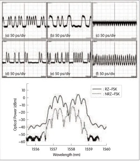
▲Figure 2.The measured waveforms for(a)non-return-to zero(NRZ)FSKtone 1,(b)NRZ-FSKtone 2,(c)NRZ-FSK,(d)RZ-FSKtone 1,(e)RZ-FSKtone 2,(f)RZ-FSK,and(g)opticalspectra curves forNRZ-FSKsignal and RZ-FSKsignal.
3.1 Comparison of Two Frequency Modulation Schemes Using MZM and PM
The phase can be changed by PM or MZM1.A PM keeps the optical intensity constant and modulates the phase subject to its bandwidth limit.However,a PM causes significant chirp on the signal.A PM introduces imperfect phase modulation in the data transition region,which causes additional power penalty.
For this reason,an MZM1is usually used for phase modulation.An MZM1produces instantaneous phase jumps at the expense of some residual IM.Although the difference between the PM and MZM1is not critical when the center frequencies of the two beams are properly aligned,impairments from timing misalignment can be caused by this difference.When timing is misaligned,the data transition region of another beam center frequency is located in the mid-point of the data time slot of the FSK signal.Therefore,by using MZM1,data-related dips inevitably lead to inter-symbolinterference(ISI)to the FSKsignal.For the PM,if the bandwidth of the OBPFis sufficiently large so that the signal keeps its constant intensity after filtering,ISIcan be avoided.However,in strong opticalfiltering systems,or for sharp-edged input data pulses,dips may also be introduced after filtering.Therefore,MZM1and PM schemes should be compared.
We run Monte-Carlo numerical simulations to investigate frequency modulation between PM+MZDIand MZM+MZDI.By substituting the PM with an MZM,receiver sensitivity can be improved by approximately 0.51 d B.This improvement is due to the fact that the upward overshoots can be partly pre-compensated for by the downward intensity dips of MZM modulation.Hence,MZM+MZDIis more suitable than PM+MZDIfor frequency modulation in terms of receiver sensitivity.MZM+MZDIhas higher receiver sensitivity than PM+MZDI.
3.2 Effect of a Different FTS
In the optical FSKgenerating technique,the FTSshould be well-preserved to ensure one beam is at the maximum transmission of the MZDIand the other is at the minimum.This is especially important to the center frequencies of the two beams.Using a different FTSto generate an FSK signal changes the transmission performance.The FTSis given by(14).Fig.3(a)shows the bit-error ratio(BER)the two FSK signals.The power penalty after transmission for a 40 Gb/s FSK with 60 GHz FTSis 0.58 d B,and the power penalty after transmission for a 40 Gb/s FSKwith 100 GHz FTSis 0.46 d B.The bandwidth of the discrimination filter is set to 60 GHz and 100 GHz for the two FSK signals.Fig.3(b)to(e)shows the eye diagrams at BER=10-9for the two FSKsignals in back-to-back and after 80 km transmission link.Clear and open eyes show convincingly the feasibility of the generated FSK scheme.Pulse timing jitter increases as spectral overlapping increases between the two FSK components.Hence,the FSK signal with 100 GHz FTSis superior in terms of power penalty,and sampling and deciding are easier in the receiver.
3.3 Comparison of Transmission Properties of FSK,DPSK,and RZ
In Fig.4,one erbium-doped fiber amplifier(EDFA)is placed at the beginning of each span to compensate for signal attenuation in the SMFand DCFand is followed by a variable opticalattenuator(VOA)to adjust the span launch power.For long-distance transmission,dispersion compensation is always compensated for in each amplifier span.Each fiber span consists of 80 km SMFwith dispersion-matching DCF.The optical fiber parameters for long-distance transmission are shown in Table 1.
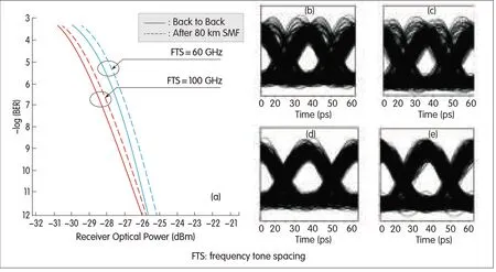
▲Figure 3.(a)BERcurves for back-to-back FSK(with 60 GHz FTS,100 GHz FTS)and after100 km SMFlink,(b)eye diagramof demodulated FSKwith 60 GHz FTSfor back-to-back and(c)after 80 km SMF,(d)eye diagram of demodulated RZ-FSKwith 100 GHz FTSfor(d)back-to-back and(e)after 80 km SMF.
System performance under different dispersion compensation schemes can be determined through simulation.A 1 d B tolerance range of the compensation ratio is between 98%to 102%,corresponding to a residual dispersion of 26 ps/nm,which is almost half the dispersion tolerance of RZ and DPSK.In this simulation,the DPSK signal is produced by a PM,and the RZsignalis generated by push-pull RZ modulation followed by NRZ modulation.Because of the relatively large signal bandwidth,dispersion should be carefully managed in the transmission of the FSK signal.
Fig.5 shows how the dispersion compensation scheme and span input power affect system performance over 11 spans of 80 km transmission link.Multispan transmission over 880 km SMFis achieved for FSK.If the receiver sensitivity is defined as the received optical power at BERof 10-9,and given the same sensitivity penalty,DPSKhas the maximum reach,and RZ has the minimum reach.For FSKand DPSK,post-compensation results in better performance than pre-compensation.However,for RZ,pre-compensation is preferred.Fig.5 shows the tolerance to nonlinearity where the sensitivity penalty is calculated from the input power of each span.At low power,performance is degraded by amplified spontaneous emission(ASE)noise from the amplifiers.If the power is increased,self-phase modulation and dispersion degrades the signal.Between the two extremes,the optimal input power range is approximately 5 d Bm to 8 d Bm for FSK.The generated FSKsignal has high tolerance to fiber input power for long distance transmission with post-compensation.
3.4 Performance of FSK with Different Dispersion Compensation Schemes
In this section,we show how dispersion compensation schemes affect performance of the FSK transmission system.At present,there are several techniques,including dispersion compensating fiber(DCF)and fiber bragg grating(FBG),that can be used to compensate for accumulated dispersion in the fiber.In the following,we describe pre-compensation,post-compenstion,and hybrid compensation for compensate for fiber dispersion.We use an ideal DCFfor the dispersion compensation schemes.The DCFis placed at different points in each transmission span.
Fig.4 shows the pre-compensation,post-compensation,and hybrid-compensation configurations.In each scheme,we use two EDFAs before and after the fiber link to compensate for and adjust the input power.In pre-compensation,the DCFis placed before the SMF.In post-compensation,the DCFis placed after the SMF.In hybrid compensation,the DCFis placed first,followed by the SMFand DCF.In these three schemed,the transmission spanlength is 80 km.Fig.6(a)to(c)shows the sensitivity of the receiver to the FSKsignal for the three compensation schemes.Receiver sensitivity depends on SMFlength and input power.The optimum span input power in each of the schemes is approximately 10 d Bm.Post-compensation has the best tolerance to residual dispersion,and receiver sensitivity is below 1 d B.When the sensitivity power exceeds-20 d Bm,post-compensation can tolerate about 60 ps/nm residual dispersion more than the other schemes.The optimized compensation ratio in the three schemes is less than 100%,and the dispersion compensation ratio degrades if the input power in each span is increased.Moreover,post-compensation has considerable tolerance to the power level.Post-compensation has very low receiver penalty and up to 25 d B tolerance of input power.Thus,transmission performance of post-compensation in transmitting an FSK signal is better than that of pre-compensation or hybrid compensation.

▼Table 1.Opticalfiber parameters
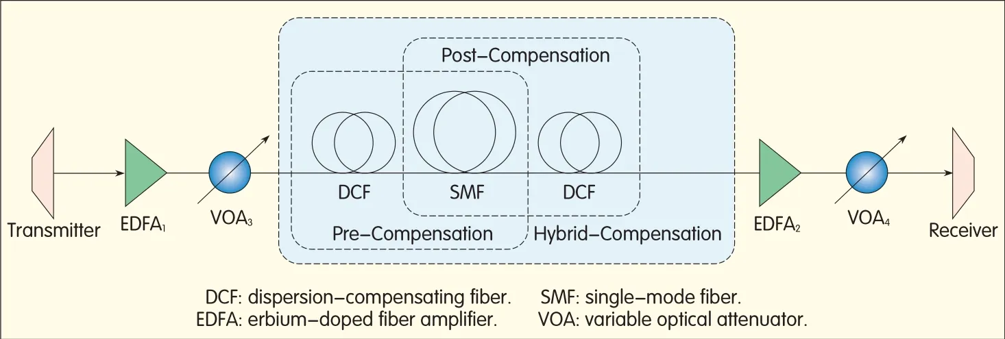
▲Figure 4.Transmission link with three differentschemes to compensate the fiber dispersion.

▲Figure 5.Receiver sensitivity penalty as a function of the span input power and the number of spans for(a)FSKwith post-compensation scheme,(b)DPSKwith post-compensation scheme and(c)33%RZwith pre-compensation scheme.
In the simulation,we found that dispersion tolerance in the post-compensation scheme is 95 ps/nm,and is the highest of all the compensation schemes.The optimized dispersion compensation ratio in each scheme is less than 100%.Full compensation or overcompensation causes pulse broadening,and transmission performance is degraded.In the different schemes,dispersion tolerance is at the maximum when the input power is 10 d Bm.When the input power is relatively small,the power penalty is higher.On the contrary,when the input power is high,fiber nonlinearity causes power loss.Post-compensation has the lowest power penalty;that is,when the input power is constant,post-compensation has the largest eye-opening.In practice,FSKsignals should be transmitting in a long distance optical transmission link using post-compensation.
3.5 Performance of RZ-FSK with Different Dispersion Compensation Schemes
Fig.1 shows the transmitter that generates the RZ-FSK signal can be divided into transmitter unit,fiber link unit,and receiver unit.In the simulation,the signalbit rate is fixed at 40 Gb/s,and the FTSof RZ-FSKis 100 GHz.For each compensation scheme,the transmission span consists of 80 km of SMF.
Fig.7 shows how fiber input power affects receiver sensitivity in the three schemes.The optimized fiber input power in the three schemes ranges from 5 d Bm to 15 d Bm.Each of the schemes has a low receiver penalty and considerable resilience to fiber input power.Furthermore,post-compensation performs the best for transmitting RZ-FSK signals.
In Fig.6 and Fig.7,transmission performance of FSK and RZ-FSK formats is compared.In the three schemes,transmission using the RZ-FSKformat is preferable for an FSK format with NRZ shape.First,the receiver power penalty using the RZ-FSKformat is lower than that using the FSK format.Second,the RZ-FSKhas high tolerance of input power level.
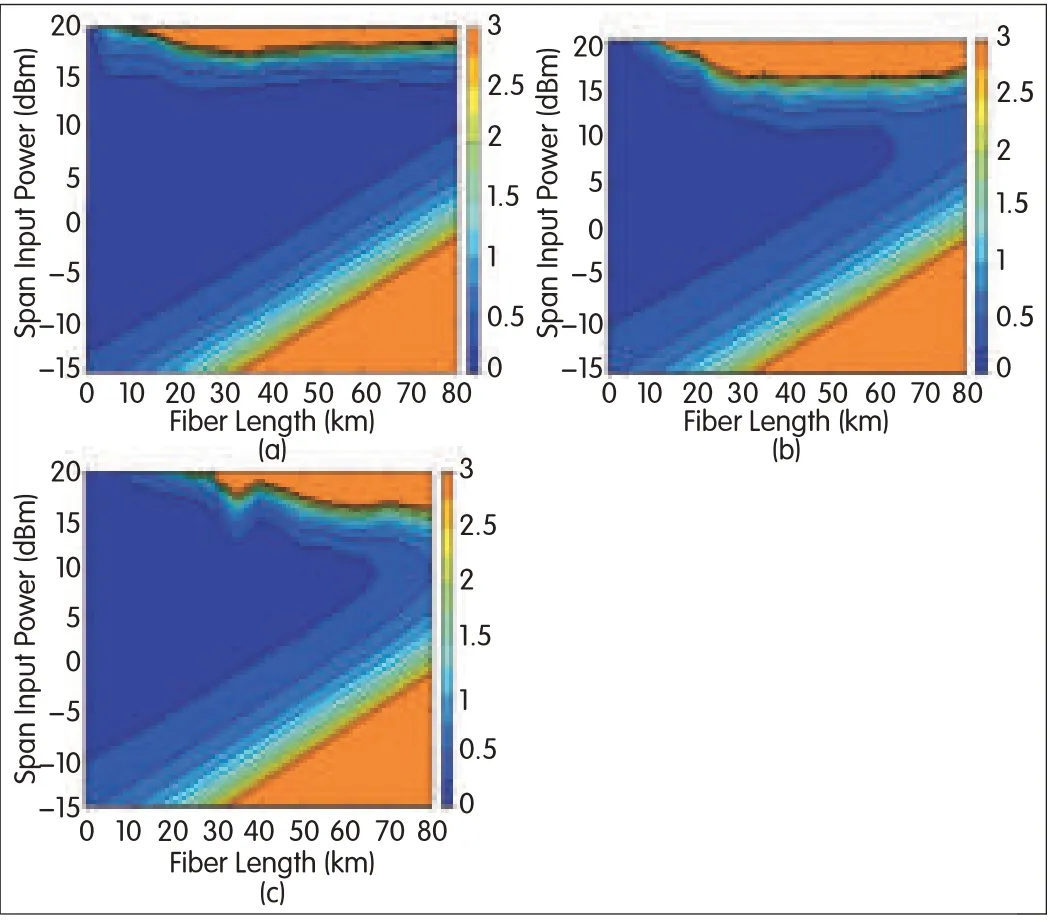
▲Figure 6.Contour plotof receiver sensitivity for the FSKsignalas a function of Inputpower and fiber length for(a)post-compensation,(b)pre-compensation and(c)hybrid compensation.
Finally,the RZ-FSK modulation format also has the good dispersion tolerance.We compare FSKand RZ-FSKformats to find the optimum frequency modulation format for high-bit-rate optical transmission systems.Receiver sensitivity is higher for RZ-DPSK than for RZ-FSK.However,for RZ-DPSK and RZ-FSK,pre-compensation provides lower receiver sensitivity than post-compensation.Hybrid compensation provides the highest receiver sensitivity for RZ-DPSK or RZ-FSKsignaltransmission.Post-compensation provides higher receiver sensitivity than pre-compensation,which is similar to hybrid compensation and is easily to implement practice.Therefore,dispersion post-compensation is chosen for our experiment on RZ-FSK signal transmission.
▲Figure 7.Contour plotof receiver sensitivity for the RZ-FSKsignal as a function of input power and fiber length for(a)post-compensation,(b)pre-compensation and(c)hybrid-compensation.
3.6 Performance of RZ-FSK Signal in a 4×40 Gb/s WDM Transmission System
Wavelength division multiplexing(WDM)transmission at 40 Gb/s/channel is a hot topic in high-speed optical transmission.The main aim of such transmission is to achieve high spectral efficiency and overcome limitations to transmission distance cause by fiber nonlinearity and chromatic dispersion.In this section,we analyze RZ-FSK signals with different FTSs.We determine advantages and disadvantages in terms of spectral efficiency,tolerance against fiber nonlinearity,and chromatic dispersion in a 4×40 Gb/s WDM transmission system.We show linear cross penalty as a function of channel spacing for both signal formats in a four-channel WDM configuration.We use flat-top AWGs for wavelength multiplexing and de-multiplexing(Fig.8).The optical bandwidth of the AWGs is set to three quarters of the channel spacing.The PRBSpattern length is 223-1.The PRBSpatterns in the neighboring optical channels are offset by 25%of the total pattern length for de-correlation.Fig.8(a)(insert)shows the WDM optical spectrum for an RZ-FSK signal with 100 GHz FTS,and Fig.8(b)(insert)shows the WDM opticalspectrum of an RZ-FSK signal with 60 GHz FTS.Both signals have double FTSchannel spacing.Fig.8(a)and(b)shows the crosstalk penalties at the center channel(the second channel)as a function of channel spacing.As the channel spacing is reduced,the linear crosstalk penalty gradually increases.For the same channel spacing,the eye-opening penalty(EOP)for the RZ-FSK signal with 100 GHz FTSis lower than that of the RZ-FSKZsignal with 60 GHz FTS.Kerr nonlinearity and chromatic dispersion of the fiber are significant issues of deterioration in WDM systems and cause EOP.The ITU G.692 proposal has three channel spacings for WDM application:50 GHz,100 GHz,and 200 GHz.Spectralefficiency in the RZ-FSKformat(if it is intended for WDM transmission)has a limitation.The channel spacing must be greater than or equal to the FTS;otherwise,crosstalk occurs between channels.To avoid linear crosstalk as much as possible,the WDM source in our configuration includes four DFB lasers with a frequency spacing of 200 GHz.The centre frequencies of the generated RZ-FSK signals are 193,193.2,193.4,and 193.6 THz,which conforms to the ITU-standard.In a 4×40 Gb/s WDM transmission system,two RZ-FSKsignals(both with 100 GHz or 60 GHz FTS)are transmitted and received over 4×80 km spans of SMFfollowed by DCF.Fig.9(a)and(b)shows receiver sensitivity as a function of input power.RZ-FSK modulation with 100 GHz FTSis more tolerant of Kerr nonlinear distortion than RZ-FSK modulation with 60 GHZFTS.RZ-FSKwith 60 GHz FTShas more compact optical spectra than RZ-FSK with 100 GHz,but RZ-FSK with 100 GHz is more suitable for WDM transmission systems because its transmission performance is better.
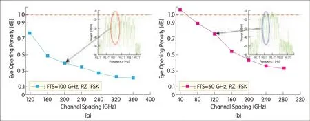
▲Figure 8.Measured eye opening penalty versus channelspacing for RZ-FSKwith(a)100 GHz FTS,(b)60 GHz FTSin 4×40 Gb/s WDMtransmission system.
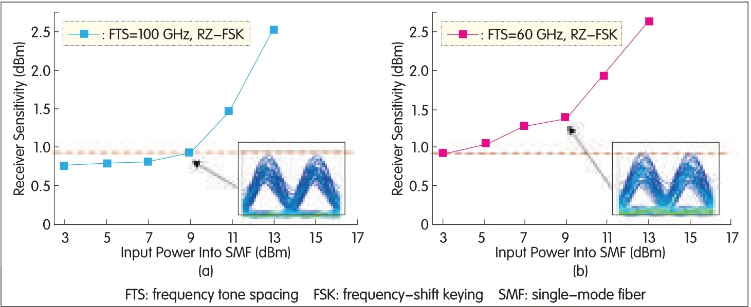
▲Figure 9.Measured receiver sensitivities versus different inputpowers into SMF-28 for RZ-FSKwith(a)100 GHz FTS,(b)60 GHz FTSin 4×40 Gb/s WDMtransmission system.
4 Experiment Setup and Results
Fig.10 shows the experiment setup.The signal sources include one external cavity laser(ECL)at 1557.64 nm and a tunable laser at 1558.46 nm with 100 GHz FTS.In this experiment,we launch an RZ-FSK signal with 100 GHz FTS,because it has better transmission performance than an RZ-FSK signal with 60 GHz FTS.Two beams can be generated by an MZM driven by 50 GHz clock.The data at 40 Gb/s(PRBS 223-1,ITU-TG.709 FEC)is generated by an SHFBPG44EBTpattern generator and added to the MZM1.The phase-modulated signal is then demodulated by the MZDIwith 25 ps delay,and this creates a 40 Gb/s FSKsignal.MZM2 is driven by 20 GHz clock and is used to generate the RZ-FSK signal.The output power of the two lasers has to be fine tuned so that the optical pulse of the RZ-FSK transmitter is relatively constant.The transmission span consists of 100 km of SMFwith a matching length of DCF for post-compensation.We choose post-compensation in the experiment because the simulations show that receiver performance in post-compensation is good,and post-compensation is easily implemented in practice.The SMF dispersion at 1550 nm is 16.9 ps/nm/km,and the DCF dispersion at 1550 nm is-100 ps/nm/km.In each span,the SMFinput power is 6 d Bm,and the DCFinput power is 0 d Bm.
Optical wavelength conversion(OWC)technology is important in large-capacity optical networks because it can reduce the probability of blocking,and it allows interconnected links and distributed network management.To the convert wavelength of a high-speed RZ-FSK signal,an interferometer based on cross-phase modulation(XPM)in the SOA cannot be used;instead,a transparent wavelength conversion scheme must be used to preserve the frequency information.By using FWM in fibers,it is possible to implement a modulation-transparent wavelength converter.Recent FWM wavelength conversion experiments also show that using HNDSFcan result in large spectral and dynamic ranges.Therefore,wavelength conversion using SOAor HNDSFis an idealway of transparently converting wavelength conversion of an RZ-FSK signal.
The pump source is an ECLat 1554.8 nm.The RZ-FSK signal is amplified and combined with the pump after polarization alignment.FWM occurs in the 300 m long HNDSF with a nonlinear coefficientγ=10 W-1km-1.The zero dispersion wavelength of the HNDSFis 1556 nm,and the dispersion slope is 0.022 ps/nm2/km.The SOA is 500μm long with a 200 mAdriving current.An OBPF1 with 1 nm bandwidth is used to filter out the converted signal.Fig.11 shows the optical spectra at the output of the HNDSFand the SOA.FWM conversion efficiency of to-19 d B can be achieved in SOA,and conversion efficiency of up to-21 d B can be achieved in HNDSF.Fig.12 shows the BER of the RZ-FSKsignal for back-to-back and wavelength conversion.Because the FWM in fibers can be exploited to achieve all-optical reshaping,the ERof the converted FSK signal is enhanced.This is confirmed in our experiment.2Rregeneration is observed in HNDSF.The sensitivity to the converted RZ-FSK signal is improved by 1.8 d B and results in less than 2 d Bpenalty after 100 km transmission.Fig.13 shows the eye diagrams.The converted RZ-FSK signal in HNDSFhas a narrower pulse width and higher ER,which indicates 2Rregeneration.
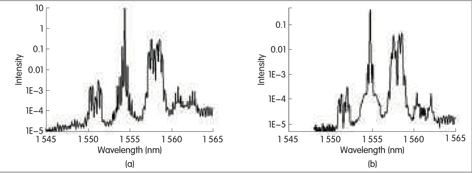
▲Figure 11.Measured FWMoutput from(a)the SOAand(b)the HNDSF.

▲Figure12.Measured BERcurves for(a)SOAand(b)HNDSF.
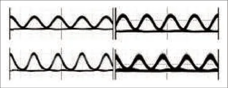
▲Figure 13.Measured eye diagrams(10 ps/div)for(a)original RZ-FSK,(b)converted by SOA,(c)converted by HNDSF,(d)converted and transmitted.
At the receiver,frequency discrimination for RZ-FSK demodulation is achieved by an OBPF2 with 0.8 nm bandwidth filter,which provides more than 25 d Bsuppression ratio between the two FSK tones.This demodulated signal is detected by a SHF 47100A V/Econverter and BERis measured by SHFEA44 error analyzer.
We also measured BERin RZ-FSK transmission.Fig.14(a)shows the measured BERcurves before and after the transmission link,where error-free transmission in RZ-FSKand FSK occurs.The power penalty for FSK at BER=10-9 is about 5.0 d B.The transmission penalties for tone one and tone two of RZ-FSK are both less than 5 d B.Fig.14(b)to(e)shows eye-diagrams of FSKand RZ-FSK for back-to-back,and after transmission through a 100 km SMF transmission link with matching DCF.Because FSK is orthogonal to intensity modulation and vector modulation(polarization shift keying),it can be used in the context of the combined modulation format to decrease the data rate or enhance the symbol rate.It can also be utilized in the orthogonal labeling as the modulation format for the payload or the label.
5 Conclusion
In this paper,we have proposed a new optical modulation transmitter that transmits RZ-FSKsignals by using two CWlasers,an MZM,an MZDI,and another MZM driven by a sinusoidal voltage at half the bit rate.The demodulation can be simply achieved on one bit rate through one MZDIor an AWG demultiplexer with balanced detection.Using numerical simulation,MZM and PM was analyzed and the effect of different FTSs on the generated FSKsignal were determined.The advantage of the proposed frequency modulation scheme is that the FTSof the generated signal is tunable by changing the center frequencies of two used lasers.For high speed transmission,it is useful to adjust the FTSand achieve higher receiver sensitivity.Moreover,this proposed scheme is simple and potentially inexpensive.We also experiment with transparent wavelength conversion based on FWM in a SOA and in a HNDSFfor a 40 Gb/s RZ-FSK signal.We have analyzed 40 Gb/s RZ-FSK signal transmission over 100 km SMFlink with matching DCF.The results of our experiment suggest that RZ-FSK modulation could be a promising candidate for future high-speed transmission system and optical label-switching networks.
Acknowledgments
This work was supported by the National High Technology Research and Development Program(973)of China(Grant No.2010CB328300),and National Natural Science Foundation of China(No.61107064,No.61177071,No.600837004,No.60777010),Doctoral Fund of Ministry of Education,Open Fund of State Key Lab of ASICamp;System(No.11MS009),Pujiang Fund and Shuguang fund.
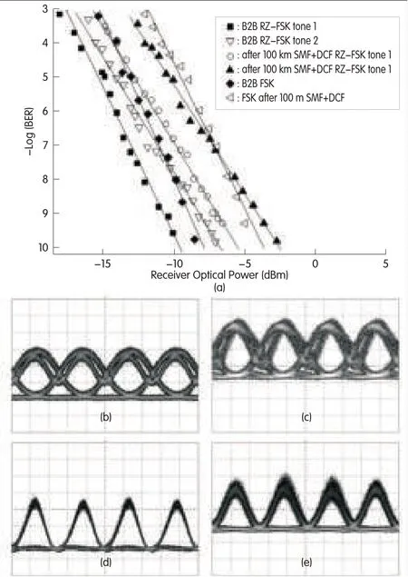
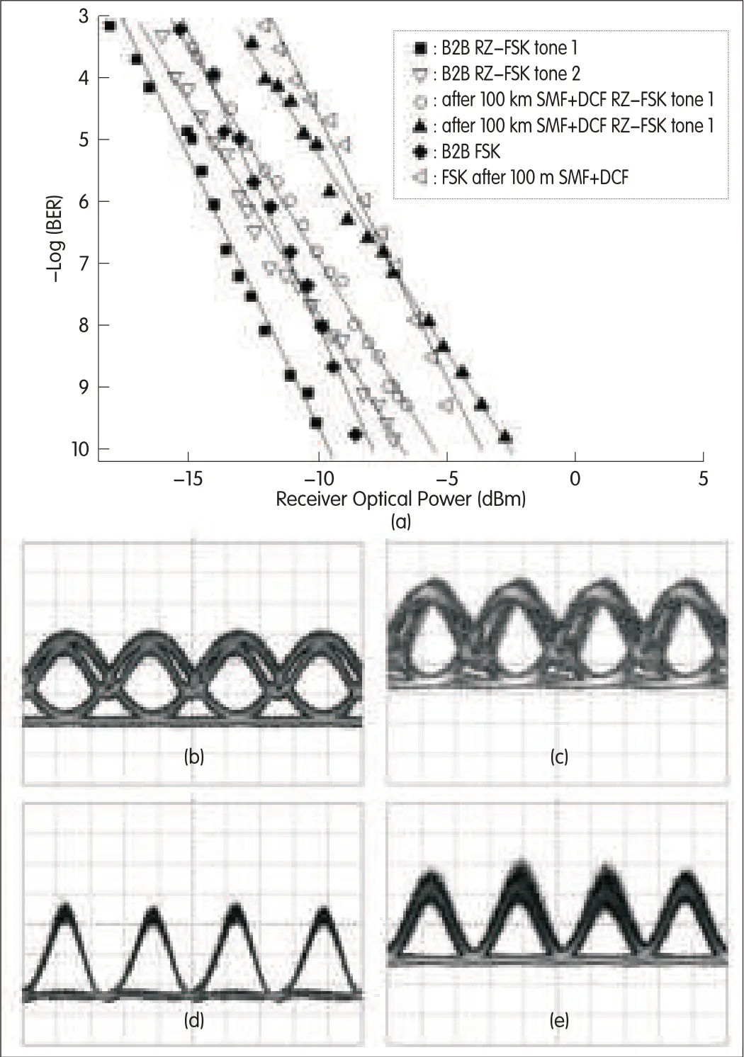
▲Figure 14.Measured BERcurves for back-to-back RZ-FSKand after 100km SMF+DCFlink(a),the eye diagram of demodulated FSK(10 ps/div)for(b)back-to-back(c)after 100 km SMF+DCF link,the eye diagram of demodulated RZ-FSKfor(d)back-to-back and(e)after 100 km SMF+DCFlink.
- ZTE Communications的其它文章
- 100Gand Beyond:Trends in Ultrahigh-Speed Communications(Part II)
- Computationally Efficient Nonlinearity Compensation for Coherent Fiber-Optic Systems
- Flipped-Exponential Nyquist Pulse Techniqueto Optimize PAPRin Optical Direct-Detection OFDMSystems
- 100 Gbit/s Nyquist-WDM PDM 16-QAM Transmission over 1200 km SMF-28 with Ultrahigh Spectrum Efficiency
- Field Transmission of 100Gand Beyond:Multiple Baud Ratesand Mixed Line Rates Using Nyquist-WDMTechnology
- Open Augmented Reality Standards:Current Activities in Standards-Development Organizations

