
An Antenna Diversity Scheme for Digital Front-End with OFDM Technology
2011-06-19 11:08FaLongLuoWardWilliamsandBruceGladstone
ZTE Communications 2011年4期
Fa-Long Luo,Ward Williams,and Bruce Gladstone
(Element CXI,San Jose,CA 95131,USA)
Abstract:In this paper,we propose a new antenna diversity scheme for OFDM-based wireless communication and digital broadcasting applications.Compared with existing schemes,such as post-fast Fourier transform(FFT),pre-FFT,and polyphase-based filter-bank,the proposed scheme performs optimally and has very low computational complexity.It offers a better compromise between performance,power consumption,and complexity in real-time implementation of the receivers of broadband communication and digital broadcasting systems.
Keyw ords:OFDM;digital front-end;MIMO;cross-layer processing;diversity;antenna
1 Introduction
I n modern wireless broadband communication and digital broadcasting,orthogonal frequency-division multiplexing(OFDM)-based modulation schemes are usually used.However,an OFDM system has very poor reception when there is noise,interference,or moving objects.To solve this problem,many technologies have been proposed and used in real applications[1],[2].Among these technologies,beamforming-based diversity technology is the most promising.It uses multiple antennas at the receiver side and spatial filtering to optimize reception in noisy and mobile environments.Figs.1,2,and 3 show three representative solutions:pre-fast Fourier transform(pre-FFT),polyphase filter-bank,and post-FFT[1],[4],[5],[7],[8].
In Fig.1,X1(n),X2(n),...,XM(n)are the received signals in one of M antennas,and W1(n),W2(n),...,WM(n)are the weights applied to these antenna signals.All the weighted signals are summed to one channel,such as one antenna’s output and then forwarded for further FFTprocessing,which is required in any OFDM-based receiver.These weights are designed to meet an optimization criterion,and the most common criterion is the maximum ratio combination(MRC).
With MRC,the optimized weight vector,W(n)=[W1(n),W2(n),...,WM(n)],can be obtained by


▲Figure 1.Pre-FFTscheme[1].
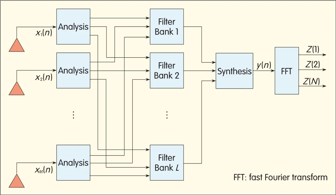
Figure 2.▶Polyphase bankscheme.
where X(n)=[X1(n),X2(n),...,XM(n)]and y(n)=WH(n)X(n).Pre-FFTcan give 5-10%gain in bit-error reduction and is not complex in implementation.However,this processing is done only in the time domain,and the same weights are used over the entire frequency band(all-carriers).Because of the shortcomings of simple pre-FFT,a polyphase filter bank scheme is proposed(Fig.2).

▲Figure 3.Post-FFTscheme[1].
In a polyphase scheme,each antenna signal is divided into a number of frequency band signals,and different weights apply to different bands.This scheme can further improve performance at the cost of increased computational complexity that arises as a result of multichannel antenna signal decomposition(analysis)and multiplication of weights in each channel.Different weights in different frequency bins and bands can be used in the frequency domain,and this is called post-FFT(Fig.3).
Apolyphase scheme is a special case of post-FFT.Post-FFTperforms the best but has the greatest computational complexity.Pre-FFThas the least computational complexity but improves performance the least.Another approach is to divide M antennas into L groups.Each group uses pre-FFTand obtains L outputs.
With these L outputs,post-FFTis then used to obtain the desired outputs.Compared with the full post-FFT scheme,this alternative avoids M-L FFTcomputations at the cost of reduced performance.A diversity scheme that provides a better compromise between performance,complexity,and power consumption is highly desired.
2 The Proposed Scheme
Here,we propose a new scheme in which the number of variables computed is reduced from N×M(in post-FFT)to N+M.The scheme shown in Fig.4 performs just as well as the post-FFTscheme.
M antenna signals are weighted by the corresponding weight as the processing made in the pre-FFT algorithm in Fig.1.These M weighted signals are added together to pass through an N-tap finite impulse response(FIR)eigenfilter,after which they are input for FFTprocessing.The number of unknown variables in the proposed scheme is N+M,which is significantly less than the N×M needed in post-FFT.Furthermore,only one FFT operation is needed in the proposed scheme instead of M FFToperations in the post-FFTscheme.Here we will prove that the post-FFTscheme in Fig.3 and the proposed scheme in Fig.4 give the same frequency-domain outputs,Z(1),Z(2),...,Z(N).Using the optimization criterion in post-FFT,the variable matrix,WN×M,in Fig.3 can be rewritten as
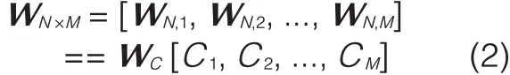
where WN,iis the i th column of the N×M matrix and denotes the weights after FFTprocessing of the i th antenna in Fig.3.WCis an N-dimensionalvector,and Ciis a scalar(corresponding to each antenna).This suggests that Figs.3 and 5 give the same outputs.
Because each block in Fig.5 is linear processing,changing the order of the blocks results in the same performance.Hence,the scheme in Fig.4 is obtained.
Now we determine the N+M weights in proposed scheme.
WE,Xh,and Xtdenote the weight vector of the eigenfiltering,the sequence of the head-guided interval,and the tail of the symbols,respectively.If the norm is a constant(unity,for instance),the weight vector is obtained in such a way that the error is minimized.That is,

According to beamforming matrix theory[3],the solution to the optimization problem is the eigenvector(minor component)corresponding to the smallest eigenvalue of the correlation matrix R,which is

This is also the reason that the filtering in Fig.4 is called eigenfiltering.In practical implementation,the minor component in the following adaptive algorithm can be updated:
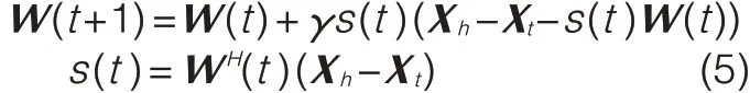
whereγis a constant.This algorithm is as complex as LMSalgorithm,and the required multiplications are only on the order of N.An algorithm,such as MRC used in pre-FFT,can be used to determine the weights applied to each antenna before eigenfiltering.
3 Comparison and Discussion

▲Figure 4.Proposed scheme.
Compared with existing solutions,theproposed scheme has the following features:

▲Figure 5.Alternative scheme for post-processing.
•The parameters to be computed in a real-time implementation are reduced from M×N to N+M,and performance remains the same as that of post-FFT.
•Only one FFToperation is needed instead of multiple FFTcomputations or polyphase filtering analyses.Table 1 shows computational complexity for various standards.
•The related parameters can be adaptively updated from the received samples of the each antenna.The adaptive algorithm used is as simple as the LMSalgorithm,which has the computational complexity on the order of the number of unknown parameters.
With these features,the proposed scheme is a new tool for improving reception quality in broadband wireless communications and digital broadcasting.It will have very many practical uses in devices.
4 Conclusions and Future Work
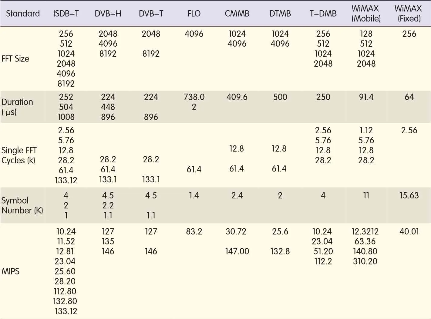
▼Table 1.Parameters related to implementation of FFTin differentstandards
In this paper,we have proposed a new and efficient diversity scheme for OFDM-based receivers.We have also shown the accuracy and effectiveness of the proposed scheme.When embedding this algorithm into real silicon,it is often desirable that one platform support all existing standards(and their various modes)with high power efficiency,low cost,and short time to market[9].Traditional integrated circuit technologies,such as application-specific integrated circuits(ASICs)and digital signal processors(DSPs),are not highly flexible and power efficient.An ASIC solution gives high performance with low power consumption and price,but it cannot support multiple standards nor is it sufficiently flexible.A DSP is highly flexible but performs poorly and consumes much power.It may include high-speed arithmetic operations,such as multiply-accumulate,but the algorithms require extensive programming and more parallelism than can be offered by a general DSP.
One alternative is to use a general DSPor reduced instruction set computing(RISC)processor plus hardware accelerators that are designed and optimized to implement FFTalgorithm as wellas eigenfiltering and its adaptive algorithm.In other words,an eigenfiltering unit performs a basic filter computation,an FFTunit performs FFTcomputations,and an adaptive unit implements the operations defined by(5)in section 2.These optimized accelerators may meet performance goals,but the accelerators are very narrow in their applicability,and this significantly reduces the flexibility of the processor-based solution.
An alternative that offers flexibility and parallelism is devices with FPGAs.These devices may combine processors with a programmable array of low-level logic devices,but they are expensive,and performance is limited at high temperatures.
In a future paper,we will introduce elemental computing array(ECA),which is designed to achieve a better compromise between performance,flexibility,cost,and power efficiency.With ECA,the FGPA scheme can have performance,power,and cost similar to ASICs.ECA is far more flexible than a DSPwith accelerators.It is also much cheaper and consumes far less power than FPGAdevices.

- ZTE Communications的其它文章
- Advances in Digital Front-End and Softw are RFProcessing:PartⅡ
- Frost&Sullivan Recognizes ZTE as 2011 LTEVendor of the Year
- ZTE Establishes Global Consumer Brand Ambitions in 2011
- Polyphase Filter Banks for Embedded Sample Rate Changes in Digital Radio Front-Ends
- Design of Software-Defined Down-Conversion and Up-Conversion:An Overview
- Practical Non-Uniform Channelization for Multistandard Base Stations