Bitron’s Theory and Design
LIAO Xu, REN Xue-zao, and LI Zheng-hong
(Science College, South-western University of Science and Technology Mianyang Sichuan 621010)
Bitron’s Theory and Design
LIAO Xu, REN Xue-zao, and LI Zheng-hong
(Science College, South-western University of Science and Technology Mianyang Sichuan 621010)
A structure of a high power microwave oscillator based on the couple between two cavities is proposed and studied. The structure composes of two cavities and a drifting tube. The couple between two cavities is important for the oscillation to occur under the controlled condition. The structure acts more like a klystron than a distributed traveling wave device. As a result, the oscillator has higher efficiency and its working mode is controlled without mode-competition. The large signal physic process is studied based on the self-consistent theory and the interaction factor k is introduced to study interactions between the beam and the structure. Finally, a conceptual design of a S-band bitron driven by a 700 keV, 10 kA electron beam has been designed.
backward wave oscillator; high power microwaves; klystron; monotron; self-consistent equation
1 Introduction
New applications for high-power microwaves(HPMs)have stimulated interests in the development of HPM devices from the conventional microwave tubes[1]. Though there exists many similarities between HPM devices and conventional microwave tubes,differences emerge continuously. The most common one is the RF pulse shortening in the HPM devices[2-3].Taking advantage of structures of conventional microwave tubes, efforts of HPM devices’ designers are mainly focused on the use of various codes, such as MAGIC, KARAT, etc. The interest to the analytical theory was lost, while many important and new phenomena occurred in particle in cell (PIC)simulations and experiments. For example, not only the RF breakdown was involved in the phenomena of RF pulse shortening in the HPM devices, but also the mode-competition was. And the output power closely depends on the number of the periods[4]in relativistic backward wave oscillator (RBWO), which is significantly less than that of the conventional BWO.
Our work is focused on the development of a general formalism, which is valid for Bitron devices[5].It allows one to calculate the self-excitation conditions and the output power in the devices analytically. Such
a general theory is also useful for analyzing the large-signal physics processes in the high-power microwaves’ devices of the similar structures. The rest of the paper is organized as follows. Section 2 presents the structure of a Bitron device and its RF field distribution along the beam path. Section 3 deseribes the electron motion under the influence of the RF field,and the energy exchange between the beam and the RF filed. In section 4, the self-consistent theory is used to analyzes the RF field excitation in the structure.Section 5 gives the brief results of PIC simulation on the structure shown in Fig. 1. Section 6 summaries the results.
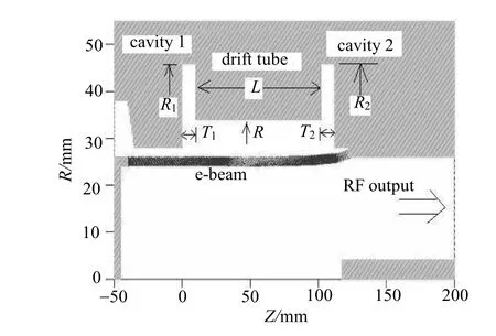
Fig. 1 Schematic structure of Bitron
2 Device’s Structure
The structure of the Bitron is shown in Fig. 1.There are two main parts in the device: two cavities and a drifting tube. And its circuit model is shown in Fig. 2, where R means RF output in the circuit. Beam will be modulated when it passes the first cavity (the modulation cavity), and it is intensely bunched when it enters the region of the second cavity. The microwave generated in the second cavity is determined by two factors: the couple between beam and the cavity, and the modulation efficiency of beam when it enters the second cavity. Table 1 summarizes the main dimensions of the structure of the device.
Fig. 2 Circuit model

Table 1 Dimensions of the devices’ structure
Fig. 3 shows the z-component RF field distribution in the interaction region, which can approximately be expressed as follows:

Where E1and E2are determined by the structure of the cavity.
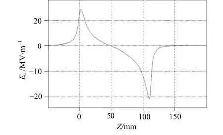
Fig. 3 Field distribution of Bitron
3 Electron motion
Let us consider the RF field excited by a beam of electrons moving linearly inside the structure. Assume that the space charge forces and the velocity spread in the electron beam are negligibly small, and in the function describing the spatial structure of the cavity RF field, we can separate the transverse and axial distribution and represent the z-component RF field of a cavity as:

Where A is the field amplitude, and E(z)describes the transverse and axial structure of the RF field inside the structure.
In principle, electron motion in the cavity can be given by[6-7]:relative factor.

The first order solution to Equation (3)can be given by:
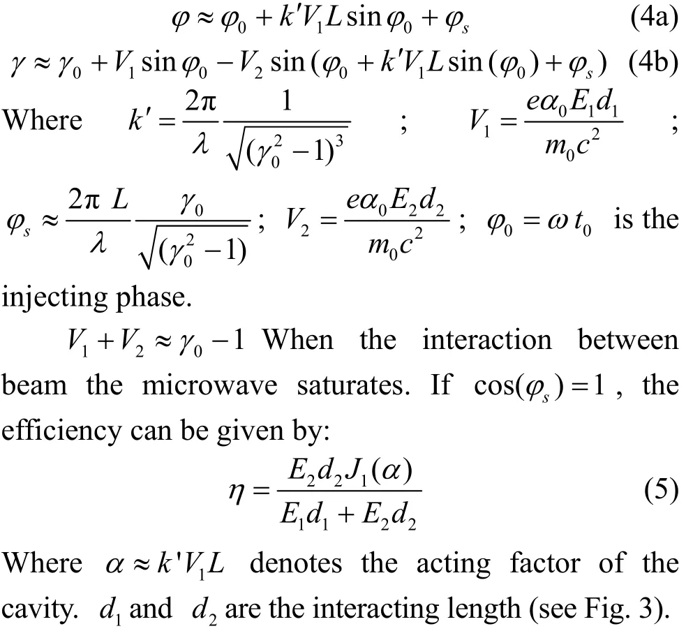
From Equation (5), the efficiency reaches the peak value when α≈1.5, and the peak value is:

4 Field Excitation

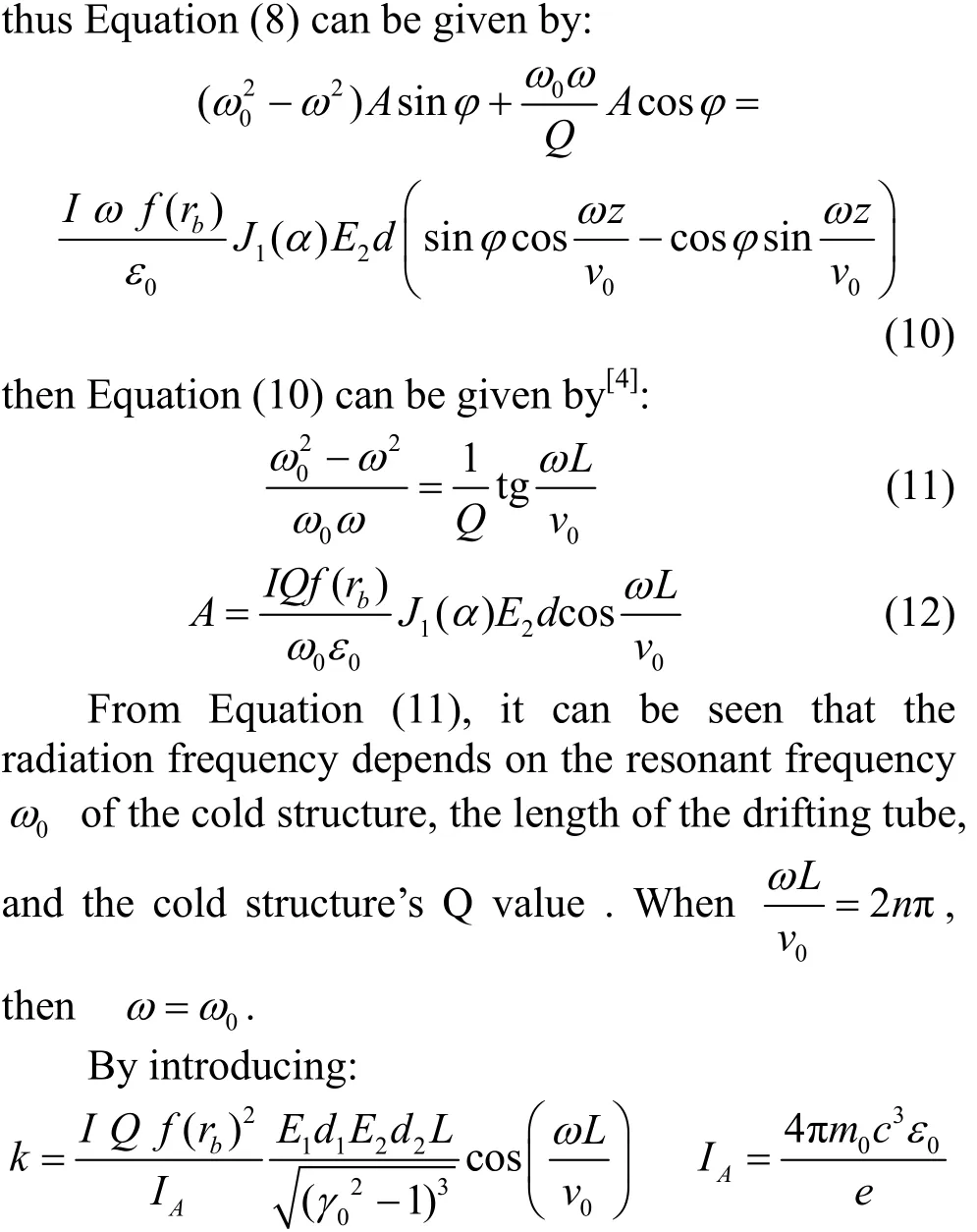
is Alfven current, which denotes the interacting factor between beam and the cavity, Equation (12)can be simplified as follows:

Fig. 4 is the curve of the interacting factor k versus the acting factor . From the curve, it an be seen that the microwave oscillation does not occur untilk>2. So k>2 is the condition for oscillations to start up which can be given by[10]:


Fig. 4 Acting factor versus interacting factor k
5 PIC simulation
The device’s structure shown in Fig. 1 is used in the PIC simulation driven by 800 kV, 12 kA beam. And the simulation results are shown in Fig. 5~7. Fig. 5 is the excited RF field in the structure when the driven beam passes. Fig. 6 is the spectrum of the RF field at the output region, and its RF frequency is 3.864 7 GHz.Fig. 7 is the curve of the output power versus time at the output port, and the output power reaches 2.65 GW.
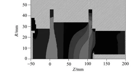
Fig. 5 RF field excited by the driven beam
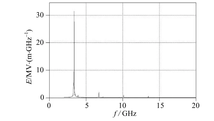
Fig. 6 Spectrum of RF field at the output region beam
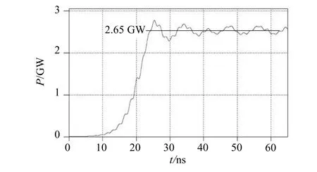
Fig. 7 Simulated output power versus time
6 Conclusions
An S-band Bitron is presented for which a 2-D PIC simulation has indicated the efficiency can reaches 28%. The system includes a simple structure. And the elementary functions for electron bunching and energy transfer to the RF filed are performed at the working mode. The mechanisms to avoid non-working mode competition are also included. Detailed studies on the simple structured Bitron tell many physical processes happened in HPM devices, and results can be a very useful tool to guide some particular HPM devices’designs in PIC simulation.
[1]KOROVIN S D, ROSTOV V V, POLEVIN S D, et al. High power microwave sources[J]. Proceedings of IEEE, 2004,92(7): 1082-1090.
[2]LI Zheng-hong. Investigation of an oversized backward wave oscillator as a high power microwave generator[J].Applied Physics Letter, 2008, 92: 054102(1-3).
[3]AGEE F J. Pulse shortening in high power microwave sources[J]. SPIE on Intense Microwave Pulses, 1996, 3702:1-8.
[4]LI Zheng-hong. Beam-loaded frequency shift in the high power microwave oscillator Bitron[J]. Physics of Plasma,2009, 8: 023107(1-4).
[5]LIU G Z, XIAO R Z. A cherenkov generator coaxial slow wave structure[J]. Journal of Applied Physics, 2008, 103:093303(1-7).
[6]LI Zheng-hong. Mode control in an over-sized backward wave oscillator[J]. Physics of Plasma, 2008, 15: 093104(1-8).
[7]CARLSTEN B E, HAYNES W B. Discrete monotron oscillator[J]. IEEE Trans on Plasma Sci, 1996, 24(4):1249-1254.
[8]LI Zheng-hong. Experimental study of a low radio frequency power driven relativistic klystron amplifier[J].Physics of Plasma, 2010, 17: 023113(1-4).
[9]KLIMOV A I, KURKAN I K. A multigigawatt X-band relativistic backward wave oscillator with a modulating resonant reflector[J]. Technical Physics Letters, 2008, 34(3):235-237.
[10]WENSTENSKOW G A, HOUCK T L. Relativistic klystron two-beam accelerrator[J]. IEEE Trans on Plasma Sci, 1994, 22(5): 750-755.
[11]JORDAN U, ANDERSON D. Microwave breakdown in slots[J]. IEEE Trans on Plasma Sci, 2004, 32(6):2250-2262.
[12]COOKE S J, NYUGEN K T. Validation of the large signal klystronsimulation code TESLA[J]. IEEE Trans on Plasma Sci, 2004, 33(3): 1136-1146.
编 辑 黄 莘
2009- 11- 13
国家自然科学基金(10347009);
廖 旭(1961- ),男,副教授,主要从事电磁场及微波理论方面的研究.
两腔微波振荡器理论和设计研究
廖 旭,任学藻,李正红
(西南科技大学理学院 四川 绵阳 621010)
提出并研究了一个基于双腔耦合的高功率微波振荡器。该结构由两个腔和一个漂移管构成,两腔之间的耦合对于在给定条件下振荡的产生有重要的影响。该结构在运行时相较于一个分布式行波器件更类似于一个速调管。结果表明,该振荡器有更高的效率且无模式竞争。在自适应理论的基础上研究了大信号物理过程,引入了互作用因子k研究电子束和该结构之间的互作用程度,并设计了一个700 keV、10 kA的电子束驱动的S波段双腔振荡器。
返波振荡器; 高功率微波; 速调管; 单腔振荡器; 自洽方程
TN102
A
10.3969/j.issn.1001-0548.2011.04.012
date:2009- 11- 13
Supported by the National Natural Science Foundation of China under Grant(10347009)
Biography:LIAO Xu was born in 1961, male, associate professor, his research interest includes electromagnetic field and microwave theory.
·通信与信息工程·

