A resistance-based sensor for the in-situ measurement of orbital atomic oxygen effects
2010-06-08 05:03:04LiuXiangpengTongJingyuXiangShuhongJiaZheng
航天器环境工程 2010年4期
Liu Xiangpeng, Tong Jingyu, Xiang Shuhong, Jia Zheng
(1.Beijing Institute of Spacecraft Environment Engineering, Beijing 100094, China;2.Harbin Institute of Technology, Harbin 150001, China)
0 Introduction
Molecular oxygen in residual atmosphere can be dissociated to AO under solar UV radiation in low earth orbit(LEO, 200~700 km).AO is the most abundant atmospheric component over this altitude range.Its number density falls with increasing altitude and varying with the season, time of the day,and most importantly, with the 11-year solar cycle.AO is much more active than molecular oxygen.Many parts of the surface of spacecraft would be eroded severely by AO bombardment, to significantly affect its operational capability or mission duration.Hence, AO is considered as one of the most dangerous environments in LEO[1].
In order to better understand the space environment for improving the prediction of both the environment and the environment effects on spacecraft, which would in turn help to define the best techniques of ground-based experiments, it is necessary to carry out flight experiments for detecting space environment and its effects and to collect flight experiment data.
Several remote sensing instruments had been used to monitor thermospheric AO before.Mass spectrometers,carbon-coated quartz crystal microbalance had been used in orbit[2].However, the size and mass prevent their use on microsatellite.Another technique called witness sample had also been used, but the requirement of retrieval of the experiment sample made it too costly to be applied[3].
The detector based on resistance sensor for AO and its effects is developed by BISEE.It is small, light, cheap and simple.The flight experiment is going to be carried out in near future.
1 The principle of the resistance-based AO sensor
The first consideration for the design of the detector is to have a conductive material that can react with AO.There are three kinds of materials: silver, carbon and osmium, which can be selected to make the resistance-based AO sensor[4,5].Table 1 shows their properties.
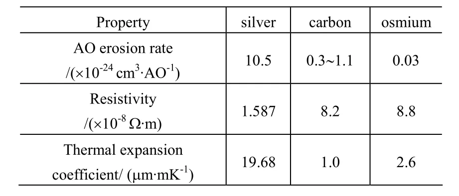
Table 1 Properties of silver, carbon and osmium
Silver has the highest erosion rate among the three kinds of materials.When it is oxidized, solid and loose Ag2O and AgO will be formed on its surface.
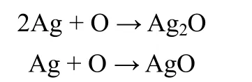
The oxide film thus formed would block the fresh silver to be further eroded by AO, so the AO erosion rate of silver is non-linear, which would result in measurement errors[6].
Carbon has a medium erosion rate.Volatile CO and CO2will be produced as the carbon is oxidized by AO.
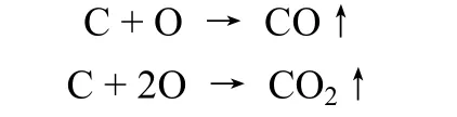
Carbon oxide is gaseous and will not block the fresh
2009-09-07;
2010-05-25
航天科技基金项目资助
刘向鹏(1974—),女,主要从事空间原子氧环境效应研究。联系电话:(010)68746648;E-mail: lxp511@sina.com。carbon to be further oxidized by AO, so its AO erosion rate is l inear.Carbon has several different structures, such as graphite, vitreous carbon and adamantine.Its structure may change in the harsh orbit environment, which will bring about a sensor resistance shift and measurement errors[7].
Osmium has the smallest erosion rate among the three kinds of materials, and when it is oxidized by AO, volatile OsO4will be produced.

Like carbon oxide, osmium oxide is also gaseous and does not block the fresh osmium to be further oxidized by AO,so its AO erosion rate is linear.Osmium is the elemental metal and its structure has good stability in the space environment,so osmium resistance sensor enjoys high measurement accuracy.
The principle of AO flux sensor is as follows:AO-sensitive resistance film is deposited on the insulation substrate of the sensor.While being exposed to AO environment, the resistance film becomes thinner as it is eroded by AO and the resistance increases.The mass loss can be computed according to the resistance change.From the erosion rate of the resistance film, the AO flux can be computed.
The principle of AO effect sensor is as follows: A space material film is deposited on the resistance film of above-mentioned sensor.While being exposed to AO environment, the resistance keeps unchanged as it is protected from AO by the space material film.But when the space material film is eroded away completely, the exposed resistance film would be oxidized quickly with a very large increased electrical resistance.The eroding time of the material film can then be determined and thus, the material erosion rate by AO can be obtained.
2 Design of the AO flux sensor
In the flight experiments for detecting the space AO flux,we concentrate on accuracy and operational life.Osmium is selected with its linear and smallest erosion rate, as well as its good stability in the AO environment.The osmium film would take longer time to be eroded than silver or carbon film with the same thickness in the AO environment.So osmium film resistance is used for the AO flux sensor.Fig.1 is the schematic diagram.
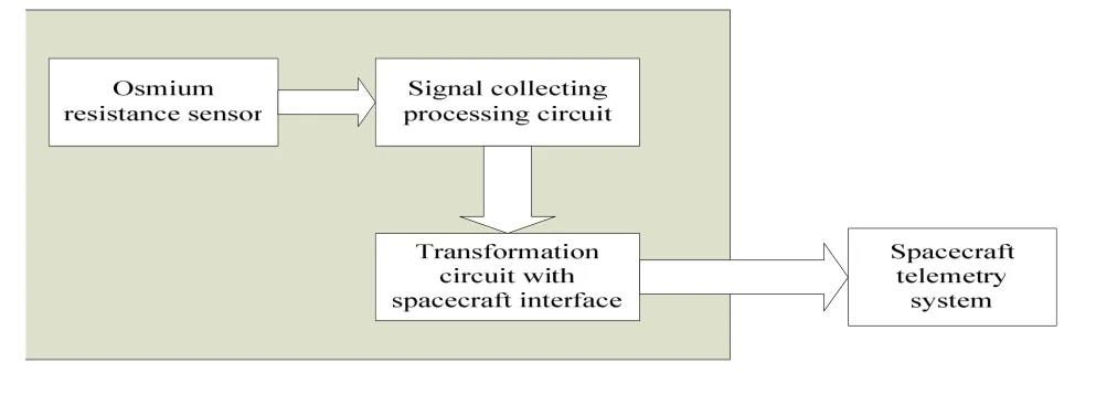
Fig.1 Schematic diagram of the AO flux detector with osmium film resistance The osmium resistance before measurement was

the osmium resistance change after a measuring period was

where:R0, Ω; ΔR, Ω;ρis the osmium resistivity, 8.8×10⁻⁸Ω·m;Lis the osmium resistance length, m;δis the osmium resistance width, m;τ0is the osmium film thickness before measurement, m;τ1is the osmium film thickness after a measuring period, m; Δτis the osmium film thickness change after a measuring period, m.
Formula (2) shows that ΔRis directly proportional toR0.The larger ΔRis, the easier it is measured.In order to increase ΔR, it is necessary to increaseR0as much as possible.Formula(1) shows that R0can be increased by increasing the length or decreasing the width of the resistance film.An osmium film of a certain dimension is cut with UV-light etching and metal etching micro processing technique, to form a resistance line with largeR0.
3 Design of the AO effect sensor
For the AO effect sensor, a switch signal (0,1) is required to indicate that the resistance turns from “no change” to “change”when the space material film is eroded away completely.Here,the signal response speed is important, while the non-linearity of the resistance change is not a problem.So silver is selected for the AO effect sensor as it has the highest erosion rate and the highest sensitivity of the response speed among the three kinds of materials.Fig.2 is the schematic diagram.
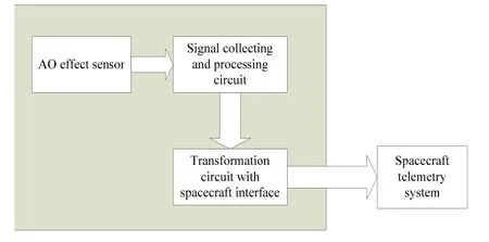
Fig.2 Schematic diagram of the AO effect detector
Then, the space experiment material film with a thickness based on 1 year working life is covered on the silver resistance film to finally make the AO effect sensor.
4 Design of the measuring circuit
At first, the resistance change of the sensor is transformed into voltage change, which is then amplified and transformed into digital signal through A/D converter.The digital signal is collected, stored, processed, packed and sent to the telemeter channel by CPU.
4.1 Measurement scheme of osmium film resistance sensor
With a small erosion rate, the osmium resistance change(ΔR) is very small during a measuring period.ΔRis therefore measured with a bridge of a four-point resistance measuring circuit to improve the accuracy by minimizing contact resistance.
4.2 Measurement scheme of silver film resistance sensor
According to the design, the sensor only has to determine if the resistance begins to change and to record the change signal, without the need to obtain the accurate value of the resistance change.With a very large silver resistance change, the design of the measuring circuit could be simple.A voltage-dividing resistance measuring circuit is adopted.
5 Preparation of the resistance sensors
5.1 Preparation of osmium AO flux sensor
The osmium film prepared with PVD process often has some cracks, mostly due to OsO2inclusion.With plating process, the osmium film can be obtained with no crack.Based on the latest studies, a perfect film of 0.25 μm thick is prepared successfully, by optimizing the plating bath’s pH value,temperature and current efficiency.Analysis of surface morphology and composition with SEM and XPS shows that the osmium film can satisfy the design requirements completely.Fig.3 is the SEM photograph of the osmium film.The surface of the osmium film is flat and smooth, as seen from the stereoscan photograph.Fig.4 is the XPS photograph and Table 2 gives the percent composition of the osmium film obtained from XPS.The content of osmium on the osmium film resistance surface reaches 99%.Then, the film is etched by UV-light etching and metal etching technique.A resistance line of 340 mm in length and 0.1 mm in width is obtained.
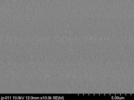
Fig.3 SEM photograph of osmium film (×10 000)
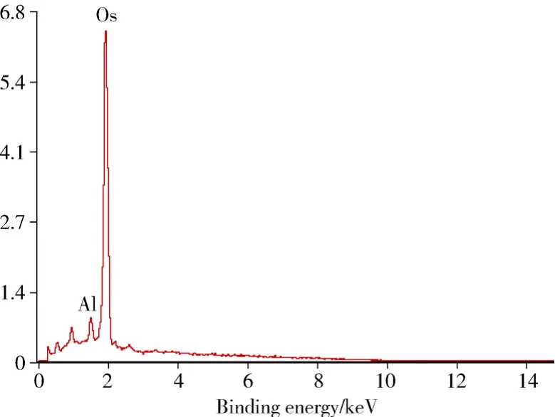
Fig.4 XPS photograph of osmium film

Table 2 The percent composition of osmium film from XPS
5.2 Preparation of silver film resistance sensor
A silver film of 20 nm thick and 1mm wide was deposited with PVD process on a quartz plate of 30 mm×20 mm×1.5 mm.
The space materials were covered on the silver film base.The space materials whose erosion rate by AO is to be determined were sprayed on the silver film base and cured in high temperature.Figures.5, 6 show the photo of the final resistance sensor.
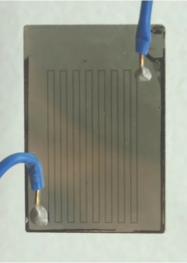
Fig.5 Sample of osmium resistance line
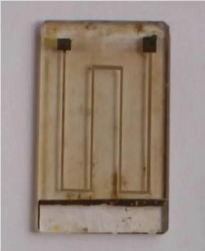
Fig.6 Sample of silver resistance line
6 Conclusions
1) AO flight experiment is the most important part in the AO effect investigation.Most data of the AO effect comes from space flight experiment.It is necessary to carefully design AO flight experiment for LEO long-life spacecraft.The resistance-based detector has the advantage of small, light,cheap and simple.It is an attractive technique.
2) Osmium AO flux sensor, silver AO effect sensor and high sensitive measurement circuit are developed in BISEE.Now, the detector engineering model is completed.We are going to carry out the flight experiment in near future.
[1]Ryden K A, Fearn D G, Alexander H X.Update on space technology research vehicle, X-26378[R]: 194-204
[2]Galica G E, Green B D, Joshi P B, et al.Atomic oxygen monitor based on carbon actinometers[C]∥Proc of the 10thISMSE & the 8thICPMSE.Collioure, France, 2006-06
[3]Osborne J J, Roberts G T, Chambers A R, et al.Initial results from ground-based testing of an atomic oxygen sensor designed for use in earth orbit[J].Rev Instrum, 1999,70(5): 2500-2506
[4]Harris L L, Chamber A R.A low cost microsatellite instrument for the in situ measurement of orbital atomic oxygen effects[J].Rev Instrum,1997, G8(8): 3220-3228
[5]Linton R C, Vaughn J A.Orbital atomic oxygen effects on materials:an overview of MFSC experiments on the STS-46 EOIM-3,N95-27637[R]
[6]Osborne J J, Harris I L, Roberts G T.Satellite and rocket-borne atomic oxygen sensor techniques[J].Rev Instrum, 2001, 72(11):4025-4031
[7]Gregory J C, Miller G P.Atomic oxygen dosimetry measurements made on STS-46 by CONCAP-2, N95-27634[R]
猜你喜欢
少儿科学周刊·儿童版(2021年22期)2021-12-11 21:27:59
少儿科学周刊·儿童版(2021年22期)2021-12-11 21:27:59
少儿科学周刊·儿童版(2021年22期)2021-12-11 06:42:32
国际放射医学核医学杂志(2020年4期)2020-07-27 01:53:28
国际放射医学核医学杂志(2020年4期)2020-07-27 01:53:22
地理与地理信息科学(2015年4期)2015-10-13 08:29:22
水利水电科技进展(2014年1期)2014-10-17 02:29:06
河南科技(2014年8期)2014-02-27 14:08:06
中国医药科学(2012年10期)2012-11-04 05:15:32
中国医药科学(2012年8期)2012-11-04 05:15:28