
All-Covalent Organic Framework Nanofilms Assembled Lithium-Ion Capacitor to Solve the Imbalanced Charge Storage Kinetics
2024-04-30 08:29:06XiaoyangXuJiaZhangZihaoZhangGuandanLuWeiCaoNingWangYunmengXiaQingliangFengShanlinQiao
Nano-Micro Letters 2024年6期
Xiaoyang Xu, Jia Zhang,, Zihao Zhang, Guandan Lu, Wei Cao, Ning Wang, Yunmeng Xia,, Qingliang Feng✉, Shanlin Qiao,3✉
ABSTRACT Free-standing covalent organic framework (COFs) nanofilms exhibit a remarkable ability to rapidly intercalate/de-intercalate Li+ in lithium-ion batteries, while simultaneously exposing affluent active sites in supercapacitors.The development of these nanofilms offers a promising solution to address the persistent challenge of imbalanced charge storage kinetics between battery-type anode and capacitor-type cathode in lithium-ion capacitors (LICs).Herein, for the first time, custom-made COFBTMB-TP and COFTAPB-BPY nanofilms are synthesized as the anode and cathode, respectively, for an all-COF nanofilm-structured LIC.The COFBTMB-TP nanofilm with strong electronegative-CF3 groups enables tuning the partial electron cloud density for Li+ migration to ensure the rapid anode kinetic process.The thickness-regulated cathodic COFTAPB-BPY nanofilm can fit the anodic COF nanofilm in the capacity.Due to the aligned 1D channel, 2D aromatic skeleton and accessible active sites of COF nanofilms, the whole COFTAPB-BPY//COFBTMB-TP LIC demonstrates a high energy density of 318 mWh cm-3 at a high-power density of 6 W cm-3, excellent rate capability, good cycle stability with the capacity retention rate of 77% after 5000-cycle.The COFTAPB-BPY//COFBTMB-TP LIC represents a new benchmark for currently reported film-type LICs and even film-type supercapacitors.After being comprehensively explored via ex situ XPS, 7Li solid-state NMR analyses, and DFT calculation, it is found that the COFBTMB-TP nanofilm facilitates the reversible conversion of semi-ionic to ionic C-F bonds during lithium storage.COFBTMB-TP exhibits a strong interaction with Li+ due to the C-F, C=O, and C-N bonds, facilitating Li+ desolation and absorption from the electrolyte.This work addresses the challenge of imbalanced charge storage kinetics and capacity between the anode and cathode and also pave the way for future miniaturized and wearable LIC devices.
KEYWORDS Covalent organic frameworks; Lithium-ion capacitor; Charge storage kinetic
1 Introduction
Lithium-ion capacitors (LICs) integrate the lithium-ion battery-type anode and capacitor-type cathode into one configuration in the lithium-salt-dissolving organic electrolyte, bridging the gap of two energy storage devices in terms of energy/power density and cycle lifetime [1].From a mechanical perspective, LICs display a distinctive and simultaneous asymmetrical charge storage process.Within these energy storage devices, lithium metal ions intercalate and de-intercalate within the anode, while anions adsorb and desorb at the cathode.As a result, two electrodes operate with discrete mechanisms across different potential ranges, contributing to the unique performance characteristics of LICs.In most reports of LICs, high energy density is typically achievable only at low currents, with a rapid decrease observed at higher currents.The primary issue lies in the imbalanced charge storage kinetics between the two electrodes.The Li+intercalation/de-intercalation process at the battery-type anode is more sluggish compared to the electrical double-layer upon polarization at the capacitor-type cathode/electrolyte interface [2, 3].Thus, achieving simultaneously competitive energy/power density, along with excellent rate capability, poses an extreme challenge involving in the entire LIC system.
At present, a wide array of active materials, encompassing transition metal oxides, sulfides, nitrides, Li4Ti5O12(LTO), Li3VO4, TiO2, and carbon-based substances [4-7], have emerged as promising contenders for anode materials in LICs.Notably, recent refreshing progress have been made in LICs mainly assembled with lithium-intercalation compounds and activated carbon (AC) as cathode and anode, respectively [8].However, LICs constructed with insertiontype materials encounter inherent challenges, especially when serving as battery-type anodes in LICs, which rely on alloying/dealloying and conversion reactions.These challenges include intrinsic poor electronic conductivity, low theoretical capacities, sluggish kinetics, and significant volume variation upon lithiation/de-lithiation [9], resulting in reduced energy and power densities, as well as compromised cycling stability.Thus, addressing this challenge and achieving enhanced electrochemical performance in LICs necessitates the development of innovative configurations for both the anode and cathode.
Considering the notable advantages over inorganic materials in the realm of LICs, such as their high specific surface area, versatile structural adaptability, extendedπ-conjugated structures, and abundant redox-active sites, porous organic polymers (POPs) emerge as another highly appealing class of electrode materials for LICs [10].Two-dimensional layered covalent organic frameworks (2D COFs), as a crystalline class of POPs, offer some distinct advantages in the Li+insertion kinetics, mainly containing the high ionic transport and electrical conductivity from their hereafter-mentioned peculiarities: (i) 2D COFs stack functionalπ-electron systems inVander Waalscontact, attaching maximalπ-orbital overlap for charge transport, and also exhibit open porous channels parallel to the stacking direction [11].(ii) Welldefined and predictable nanopores can allow the rapid ion/charge diffusion to reach the build-in active sites and simultaneously hold the electrolyte ions [12].(iii) The diversity of building blocks, coupled with atomically controllable preparation, facilitates the precise integration of redox-active groups, allowing for the customization of Faradaic redox properties within COFs [13].COFs have been investigated as promising electrode materials for supercapacitors and lithium-ion batteries [14].To the best of our knowledge, academic investigations concerning the application of bulk COFs as anode materials for LICs are still in their nascent stages.This may be mainly due to the lack of thoroughly mechanism about COF anode Li+intercalation/de-intercalation, suitable capacitor-type cathodes along with the complicated device assembly process in nonaqueous LICs.In addition, the robustπ-πstacking interactions between layers of COFs pose a constraint on the efficient transport of lithium-ions to the active sites situated within the bulk COFs.This suboptimal utilization of active sites presents a formidable obstacle for COFs in meeting the demanding criteria for high-capacity output and exceptional rate capability, essential for LIC anodes.It is worth noting that recent progresses have mainly focused on strengthening the electronic conductivity and lithium-ion accessibility of batterytype anode active materials, though the design/synthesis of novel high-rate anode nanomaterials, or hybridization with electrically conductive substrates [15-17].Nevertheless, less attention has been paid to the ordered microstructure configuration design of whole electrode, especially for overall electrode system with fast mass and free electron transfer.
In fact, there is a ceiling placed on achievable charge storage kinetics that is locked by the inevitable agglomeration/stacking of conventional electrodes.An ideal electrode configuration should effectively utilize active material domains and optimize electron/ion transport pathways throughout the electrode, without altering material chemistry [18].In our previous research, we discovered that free-standing COF nanofilms possess exceptional capacitive performance when utilized as micro-supercapacitor interdigital electrodes [19], which can be expected as the promising practical application based on the reports [20-23].Therefore, free-standing COF nanofilms have the ability to achieve the high structural integrity and interconnectivity throughout the whole battery-type anode.This is made possible by the 2D conjugated skeleton, which allows for free electron conduction andπ-π* electron transition in 3D interlayer.Additionally, 1D porous channels facilitate fast electrolyte ion transport in a longitudinal and parallel interlayer without obvious “dead volume”.However, the areal mass of COF nanofilm anode is far below that of commonly used bulk AC cathode, leading to the mass imbalance between two electrodes that enormously impacts the LIC energy density.
Herein, we propose a molecule-level structural design strategy for integrated design-construction of all-COF nanofilms, which can be used in the assembly of LICs.This involves the polymerization of COFBTMB-TPnanofilm with 2,2’-bis(trifluoromethyl)benzidine (BTMB) and 2,4,6-Triformylphloroglucinol (TP) as anode, and COFTAPB-BPYnanofilm, utilizing 1,3,5-tris(4-aminophenyl)benzene (TAPB) and 2,2’-bipyridyl-5,5’-dialdehyde (BPY) as cathode.The designed concepts are as follows: (i) COFBTMB-TPnanofilm with strong electronegative-CF3groups can adjust the partial electron cloud density for Li+migration to ensure the rapid anode kinetic process, releasing much Li+on account of F competitive advantage over PF6-electrolyte.COFBTMB-TPnanofilm provides abundant Li+storage sites from the highly reversible semi-ionic/ionic state of C-F bonds.(ii) The demonstrated capacitance-dominated charge storage processes in the COFBTMB-TPnanofilm anode permit fast kinetics for the transported lithium-ions and electrons, ensuring well-matching kinetics between cathode and anode, and contributing to outstanding performance.(iii) Porous COFTAPB-BPYfilm cathode with inherent skeleton nitrogen atoms not only provide additional charge storage sites but also match with COFBTMB-TPfilm anode in the areal mass with the same order of magnitude.The density functional theory (DFT) calculations were performed to identify Li+insertion sites and diffusion paths for COFBTMB-TPnanofilm anode.In terms of mismatch capacity from cathode/anode with different energy storage modes, the thickness of COFTAPB-BPYnanofilm cathode was optimized to fit with the COFBTMB-TPanode in the capacity.Then, the assembled COFTAPB-BPY//COFBTMB-TPall-COF nanofilm LIC is successfully fabricated and optimized in both kinetic and mass balance, demonstrating the high energy density of 318 mWh cm-3at a power density of 6 W cm-3, long cycle stability with the capacity retention rate of 80% after 1000-cycle, and good rate capability.
2 Experimental
2.1 Materials
The sodium dodecylbenzene sulfonate (SDBS, 98%) and TAPB (99.67%) were purchased from Tianjin Damao Chemical Reagent Factory, while BTMB (99.98%) and TP (97%) were obtained from Jilin Province Yanshen Technology Co, Ltd.BPY (97%) and glacial acetic acid (99.5%) were procured from Shanghai Macklin Biochemical Co, Ltd.Electrolytes (1 M LiPF6) in ethylene carbonate (EC)/dimethyl carbonate (DMC)/ethyl methyl carbonate (EMC) (volume ratio of 1:1:1) and CR2032 coin type cells were purchased from DoDochem.
2.2 Preparation of COFTAPB-BPY and COFBTMB-TP Nanofilms
The SDBS (1 mg mL-1in chloroform solvent, 20 μL) was dripped into the deionized water (50 mL) in crystal dish, to be dispersed on the liquid surface for 40 min.The TAPB monomer (1 mg mL-1in 0.12 M HCl solution) was added into the liquid phase under SDBS and maintained for 1 h.And then another BPY monomer (1 mg mL-1in 0.12 M HCl solution) and acetic acid catalyst were added to complete the polymerization reaction of TAPB and BPY monomers.After 7 days, the COFTAPB-BPYnanofilm was grown between the gas/liquid interface [24-26].
Similarly, the COFBTMB-TPfilm was synthesized by the same method, except for the TP (2 mg mL-1in 0.12 M HCl solution) and BTMB (2 mg mL-1in 0.12 M HCl solution) monomers, without additional acetic catalyst.
2.3 Materials Characterizations
The chemical structures of COFTAPB-BPYand COFBTMB-TPnanofilms were investigated by Fourier transform infrared spectroscopy (FTIR,Thermo Scientific Nicolet iS10 spectrometer), Raman (Renishaw qontor), X-ray photoelectron spectroscopy (XPS,Thermo Scientific K-Alpha spectrometer) test.The morphologies of COFTAPB-BPYand COFBTMB-TPnanofilms were observed by the optical microscope (OM,LEICA DM750M), scanning electron microscope (SEM,JEOL), transmission electron microscopy (TEM,D/MAX-2500,Rigaku) and atomic force microscope (AFM,Dimension Icon,Bruker).The surface morphologies of COFTAPB-BPYand COFBTMB-TPnanofilms were monitored by the scanning electrochemical microscopy (SECM,VersaSCAN,Advance Measurement Technology,InC) though a three-electrode system including COF nanofilms coated Si wafer, Ag/AgCl reference and probe in K3Fe(CN)6/K4Fe(CN)6electrolyte (0.1 mmol L-1).The lipophilicity of COFBTMB-TPwas tested by7Li solid-state NMR (Agilent 600M) analysis, after soaking COFBTMB-TPnanofilm in LiPF6solution.
2.4 Half-Cell and Full-Cell Assembly
The prepared COFBTMB-TPanode nanofilm was transferred to a copper foil (ϕ= 12 mm) to assemble into the half-cell device, with polypropylene film and Li metal as the separator and reference electrode, respectively, using the 1 M LiPF6in EC/DME/EMC (volume ratio, 1:1:1) (40 μL) as the electrolyte, in the CR2032 coin cell.All the assembly process was carried out in the argon-filled glove box (Etelux, water and oxygen content of less than 0.1 ppm).
Then, the COFBTMB-TPhalf-cell was treated by charge/discharge cycles at 0.1 C in the voltage range of 0-2 V versus Li/Li+on LAND battery testing system to achieve pre-lithiation of COFBTMB-TPnanofilm anode.After prelithiation, the COFBTMB-TPhalf-cell was transferred into the glove box and remove the negative tab.The obtained prelithiated COFBTMB-TPanode nanofilm was assembled into the COFTAPB-BPY//COFBTMB-TPLIC, with COFTAPB-BPYnanofilms as the cathode, in the similar process with above full-cell assembly.
2.5 Materials Electrochemical Characterizations
Electrochemical tests contain the cyclic voltammetry (CV), galvanostatic charge/discharge (GCD), electrochemical impedance spectroscopy (EIS), which can be performed in the Princeton Applied Research electrochemical workstation (VersaSTAT 3), except GCD in the LAND battery testing system.
CV measurement of COFTAPB-BPY//COFBTMB-TPLIC was performed in the potential range of 0-2 V at various scan rates from 10 to 100 mV, and GCD test with the voltage window of 0-1.5 V at different current densities from 0.01 to 0.1 mV cm-2.In these CV curves, the current can be divided into surface capacitance (k1v) and diffusion-control reaction (k2v1/2), which can be further quantified as Eq.(1) [27]:
In order to assess the charge storage capacity of these COFTAPB-BPY//COFBTMB-TPLIC devices, the important index such as areal specific capacitance (CA, mF cm-2), volumetric specific capacitance (Cv, mF cm-3), energy density (E, Wh cm-3) and power density (P, W cm-3) can be calculated based on the GCD curves, which can be derived from Eqs.(2-5) [28, 29]:
wherei(A) is the discharge current, Δt(s) is the discharge time, Δv(V) is the potential windows, A (cm2) andh(cm) are the area and thickness of active material.
EIS plots of COFTAPB-BPY//COFBTMB-TPLIC device was tested in the frequency range of 10 mHz to 100 kHz with an applied potential amplitude of 5 mV.In addition, the EIS plots of anode COFBTMB-TPnanofilm and bulk COFBTMB-TPwere also measured at different voltages ranging from 0.01 to 2 V versus Li/Li+, to determine theWarburgimpedance (Ws), which is closely related with the Li+diffusion coefficient (D’Li+, cm3s-1), as shown in Eq.(6) [30]:
wherenis the number of the electrons involved in the electrode reaction,σωvalue is the slope of Z ~ω1/2plots,C(mol cm-3) is the concentration of lithium-ions in the lattice (roughly estimated as electrolyte concentration).
3 Results and Discussion
3.1 COF Nanofilm Preparation and Characterizations
Scheme 1 illustrates the synthesis of COFTAPB-BPYand COFBTMB-TPnanofilms, which are then assembled into COFTAPB-BPY//COFBTMB-TPnanofilm LIC.The COF nanofilms were prepared through the reversible Schiff base polymerization of BTMB and TP monomers (or TAPB and BPY) using a soft template derived the surfactant SDBS.The COFBTMB-TPnanofilm was generated by undergoing the irreversibleenol-to-ketotautomerization after above reversible Schiff base reaction, which only involves the chemical bond conversion, without destroying any crystallinity [31].Considering the possible rapid energy storage kinetic process of COFBTMB-TPnanofilm with strong electronegativity-CF3groups, the COFBTMB-TPnanofilm acted as the LIC anode, to match with the capacitance-type cathode.The COFTAPB-BPYnanofilm was applied as the LIC cathode, whose thickness was optimized by controlling the concentration of adding monomers, to obtain the high-performance COFTAPB-BPY//COFBTMB-TPLIC device.
The chemical structures of COFTAPB-BPYand COFBTMB-TPnanofilms were demonstrated by FTIR, Raman and XPS techniques.As shown in Fig.S1a, the C=N stretching and bending vibration peaks newly appear in 1623 and 1252 cm-1, respectively.Additionally, the N-H stretching vibration peak at 3218 cm-1in TAPB and the-CHO stretching vibration peak at 1630 cm-1in BPY disappear.These changes can be attributed to the Schiff base reaction between the TAPB and BPY, resulting in the formation of the C=N bond in the COFTAPB-BPYfilm [32].However, the COFBTMB-TP(Fig.S1b) contains newly generated C=O at 1631 cm-1and C-N at 1188 cm-1stretching vibration peaks, confirming the occurrence ofenol-to-ketotautomerism and the accurate synthesis of COFBTMB-TPfilm [33], where the C-F bonds at 1049 and 1009 cm-1are not involved in the reaction.Meanwhile, the C=N bond at 1602 cm-1, aromatic C-H/C=C vibration bond severally at 1181 and 1542 cm-1, deformation vibration of benzene ring at 1460 cm-1[34], can be detected in the COFTAPB-BPYRaman spectrum (inset of Fig.1a).This provides an initial indication of the successful polymerization between TAPB and BPY.On the other hand, in the Raman spectrum of COFBTMB-TP(inset of Fig.1b) without the presence of-NH2,-CHO, or-OH groups, different vibrational bonds are detected: C-N at 846 cm-1, C-H at 965 cm-1, C-F at 1317 cm-1, C=O at 1594 cm-1, and deformation vibration of the benzene ring at 1455 cm-1.These observations further confirm the Schiff base reaction between the BTMB and TP monomers.It is worth noting that in the case of COFBTMB-TP, there is also evidence ofenol-to-ketotautomerization, leading to the formation of C=C-N bonds.
Figure S1c shows the P-XRD patterns of bulk COFBTMB-TPand COFTAPB-BPY, which can be used to reflect the COFBTMB-TPand COFTAPB-BPYnanofilm.The diffraction peak of (100) crystal plane appear at 2θ= 2.9° for COFBTMB-TPand 2θ= 2.2° for COFTAPB-BPY, which can be further calculate the pore size of COFBTMB-TPabout 2.9 nm and COFTAPB-BPYabout 3.9 nm.Moreover, the structural result of COFBTMB-TPand COFTAPB-BPYcan be also confirmed by simulation in Fig.S1d.The COFBTMB-TPby A-A stacking arrangement exhibits the pore size of 2.9 nm, and layer spacing of 0.44 nm.The COFTAPB-BPYby A-A stacking arrangement exhibits the pore size of 3.9 nm, and layer spacing of 0.35 nm.XPS analysis was performed to further research the chemical elements/bonds of COFTAPB-BPYand COFBTMB-TP.The C 1score-level spectrum (Fig.S2a) of COFTAPB-BPYcan be divided into C-C/C=C at 284.2 eV, C=N in imine group at 284.5 eV [35], while C-F at 292 eV, C=O at 287.9 eV, C-N at 284.5 eV, C-C/C=C at 283.9 eV for COFBTMB-TP[36], further proving the polymerization of TAPB-BPY, coupling of enol-to-keto tautomerization of BTMB-TP monomer pair.The N 1s spectrum (Fig.S2b) contains the C-N at 399.6 eV and C-N at 398.4 eV for COFTAPB-BPY, while only C-N peak at 399.5 eV for COFBTMB-TP.In addition, the unique O and F elements for COFBTMB-TPwere also analyzed as follows: C=O bond at 533.5 eV (Fig.S2c) in the O 1sspectrum, the C-F bond at 688.25 eV in F 1sspectrum, which show that the C-F bond exists in the form of semi-ionic bond in COFBTMB-TPnanofilm (Fig.S2d).

Scheme 1 Schematic synthesis of COFTAPB-BPY and COFBTMB-TP nanofilms (a); illustration of assembling COFTAPB-BPY//COFBTMB-TP nanofilm LIC (b)
The OM, SEM, TEM and AFM images of COF nanofilms were collected to observe their morphology.As shown in Fig.1a, b, the OM photographs show that the smooth and uniform nanofilms can be distinguished for COFTAPB-BPYand COFBTMB-TPnanofilms, without obvious cracks and defects, even if the SEM (Fig.1c, d) and TEM (Fig.1e, f) images at a high magnification.The recognized slight folds and edges are the typical of large-area 2D nanofilm.Notably, these COF nanofilms can be transferred into different substrates without destroying the integrity of nanofilms, indicating the high mechanical strength.The thickness of COFTAPB-BPYand COFBTMB-TPnanofilms is measured to be about 8.3 and 4.1 nm, respectively, based on AFM test (Fig.1g, h).In the 2D and 3D SCEM images (Fig.1i-l), the observed maximum current signal difference resulting from the redox reaction within the 0.5 × 0.5 mm2scanning region is about 2.5 nA.It is indicated the presence of a flat and intact film across a large surface area for the prepared COFTAPB-BPYand COFBTMB-TPnanofilms, as determined by monitoring the distance between the nanofilm surface and probe.

Fig.1 OM (a-b), Raman spectra (inset)), SEM (c-d), TEM (e-f), AFM (g-h), SECM (i-l) images of COFTAPB-BPY and COFBTMB-TP nanofilms
3.2 Electrochemical Performance of COFBTMB-TP Nanofilm Electrode
In view of the absorption of special COF on Li+, the lithium storage performance of COFBTMB-TPnanofilm was evaluated in a half-cell with lithium metal as the counter electrode.In Fig.S4, a pair of distinct oxidation/reduction peaks separately at 1.3 and 0.73 V can be detected in the CV curves of 0-2 VversusLi/Li+at scan rate of 0.2 mV s-1, corresponding to the fact as follows: (i) the F-and Li+can be bonded by the electrostatic attraction, in virtue of the C-F transformation from semi-ionic into ionic bond (charge).(ii) Afterward, the F semi-ionic bond to nearby carbocation will be reformed, to attach the Li+de-intercalation (discharge).As reported, the highly reversible conversion of C-F ionic/semi-ionic bond exists in the charge/discharge process of C-F contained 2D conductive materials [37], which can provide enormous lithium storage active sites and improve the cycle stability.In addition, there is no obvious variation for CV integral area in the first three cycles, proving that the high reversibility of Li+intercalation/de-intercalation.
The similar-shaped CV curves at different scan rates (Fig.2a) and the GCD curves at different current densities (Fig.2b) are also the signal of stable electrochemical performances of COFBTMB-TPelectrode.Based on the discharge time in GCD curves, the high areal specific capacity of COFBTMB-TPelectrode is 5.15, 3.90, 3.25, 2.86 and 2.50 μAh cm-2at current densities of 0.01, 0.03, 0.05, 0.07 and 0.1 mA cm-2, respectively.The COFBTMB-TPelectrode with only the thickness of 4.1 nm exhibits the extremely high volumetric specific capacity, contrasting significantly with currently reported commercial LiCoO2(LCO)/Li4Ti5O12electrode with the thickness of 1300 μm and an area specific capacity of 28.6 mAh cm-2[38].This proves the excellent lithium storage capacity of COFBTMB-TPnanofilm.The high specific capacity of COFBTMB-TPelectrode benefits from the unique highly ordered 1D channel, which enables full exposure of Li+to active sites, along with the presence of abundant active sites such as C-F, C=O, C-N.Moreover, because of the thickness of COFBTMB-TPfilm at nanometer level, it can overcome the problem of covering the active site by layer accumulation of powder COF material.So that all lithium storage sites can be fully utilized.In Fig.2c, it is observed that the specific capacity retention maintains about 50% even with an increased current density from 0.01 to 0.1 mA cm-2, and it still approaches to 90% when the current density cycles back to 0.01 mA cm-2.The good rate capability of COFBTMB-TPis an unattainable target especially for organic compounds.The COFBTMB-TPelectrode shows acceptable cycle performance after 1000 cycles with a specific capacity of 2.0 μAh cm-2at 0.01 mA cm-2, and coulombic efficiency with no obvious deformation (Fig.2d).This performance can be explained by the similar morphology in SEM images obtained after 300th with 1st cycle (inset of Fig.2d).Compared to the original nanofilm, the obvious solid electrolyte interface (SEI) layer can be found in the cross section of nanofilm after 1st charge/discharge cycle, which exhibit no obvious variation after the following 300 cycles.This good rate capability and structural stability can be attributed to the enhanced structure and SEI stability, which result from the covalent-bonded rigid skeleton structure and C-F bonds.
In theex situXPS spectra of COFBTMB-TPnanofilm in LiClO4(1 M, in EC:PC = 1:1 Vol%) alternative electrolyte (Fig.2e), all semi-ionic C-F bonds exist in the original state, gradually transitioning into ionic C-F bonds on account of Li+addition during charging, and further recover to semi-ionic C-F bonds due to the Li+removal during the discharge process.This realizes the highly reversible conversion of semi-ionic to ionic C-F bonds throughout the whole lithium storage process.Similarly, in Fig.S4b, c, the lithium storage mechanism of C=O and C-N bonds was also confirmed in the charge/discharge process.In the7Li solid-state NMR spectra, the chemical shift of Li+transforms from -1.622 to -1.242 ppm after adding COFBTMB-TPnanofilm (Fig.2f).This shift is attributed to the decreasing local electron cloud density caused by the presence of strong electron-withdrawing-CF3and C=O groups, confirming the interaction between COFBTMB-TPand LiPF6.In order to verify these Li+storage active sites at the theoretical level, the corresponding lithium absorption energy values were calculated usingDMol3module based on DFT.In Fig.2g, the Li+absorption energy values for oxygen (-1.37 eV), nitrogen (-1.13 eV) and fluorine (-1.31 eV) atoms in COFBTMB-TPare higher than those of PF6-(-0.82 eV), EC (-0.84 eV), DMC (-1.04 eV) and EMC (-1.11 eV) in electrolyte.This observation indicates the strong interaction between COFBTMB-TPand Li+, making it more favorable for Li+to bind with COF after separation from electrolyte.In fact, it is very difficult for the Li+absorption on C atoms, but C-F semi-ionic bond can enhance the Li+adsorption capacity of C atoms, enabling higher capacity for energy storage [39].The strong interaction between the functional groups on COFBTMB-TPskeleton and Li+is supported by the distribution of Mulliken bonds.The exceedingly low lattice energy of C=O (-0.454 eV), C-N (-0.555 eV) and C-F (-0.301 eV) bonds make it easier for them to compete with PF6-and obtain more Li+.In addition, the calculated electrostatic potential distribution of COFBTMB-TP(inset in Fig.2g) shows that the electrons in COFBTMB-TPskeleton can be transferred into C-F (red area), leading to high electron cloud density in C-F region.Therefore, the Li+migration process from electrolyte components to COFBTMB-TPis drawn in Fig.2h as follows: the lithium-ions undergo the desolvation from electrolyte component due to the strong electronegative C-F, subsequently absorbing onto the COFBTMB-TP, simultaneously affected by repulsive force of C-F on electrolyte anions.

Fig.2 CV curves at different scan rates (a), GCD curves at different current densities (b), rate capacity (c), cycling stability properties after 1000 cycles (d) and ex situ XPS spectra of C-F bonds in LiClO4 (1 M, in EC:PC = 1:1 Vol%) alternative electrolyte (e) for COFBTMB-TP electrode; solid-state 7Li NMR spectra of LiPF6 with and without COFBTMB-TP addition (f); DFT simulated Li+ adsorption energy about COFBTMB-TP and electrolyte components (g), calculated electrostatic potential distribution of COFBTMB-TP (inset, g); schematic descriptions of Li.+ migration process from electrolyte components to COFBTMB-TP (h)
3.3 Investigation of Li+ Diffusion Rate and Capacity Matching
In order to figure out the internal kinetics of COFBTMB-TPnanofilm in energy storage process, the surface capacitance and diffusion-controlled contribution for COFBTMB-TPelectrode were analyzed at a series of scan rates.In Fig.3a, the green-highlighted surface capacitance contribution constitutes a significant portion of CV integral area, amounting to 84% at a scan rate of 1 mV s-1and this contribution increases with the scan rates escalate.The proportion of surface capacitance contribution is high, reaching 70.1%, 76.8%, 80.2%, 82.4% and 84.0% at scan rate of 0.2, 0.4, 0.6, 0.8 and 1.0 mV s-1, respectively (Fig.3b).This phenomenon explains the excellent charge storage kinetics behavior of COFBTMB-TPelectrode, which perfectly match the capacitive kinetic process of the LIC cathode.This kinetic process can be also effectively evaluated by ion diffusion coefficient from EIS measurement.In Fig.3c, dynamic EIS spectra of COFBTMB-TPnanofilm at different discharge potentials exhibits the semicircular arc and straight line at high and low frequent region, respectively; these features correspond to the charge transfer resistance and ion diffusionWarburgresistance.At the ion diffusion region, these plots of Z’ versusω-1/2(Fig.3d) were summarized to calculate the slope values at different potentials (Fig.S5e), which were subsequently employed to calculate the Li+diffusion coeffi-cient based on Eq.(6).Similarly, as a comparison, the calculated Li+diffusion coefficient of bulk COFBTMB-TPcan reach 5.6 × 10⁻¹¹cm2s-1(Fig.S5f), surpassing many other electrode materials such as LiNi0.5Mn0.5O2(3.7 × 10⁻¹³cm2s-1) [40] and LFP/CZIF-8 (1.17 × 10⁻¹³cm2s-1) [41].In view of the nano-level thickness of film, the volumetric Li+diffusion coefficient at different potentials (Fig.3e) show that COFBTMB-TPnanofilm exhibits the significantly higher volumetric Li+diffusion coefficient of 1.15 × 10⁻⁶cm3s-1, compared with that of bulk COFBTMB-TP(1.86 × 10⁻⁸cm3s-1).Moreover, with the increasing potential, the attenuation of Li+diffusion coefficient appears at 1.2 V versus Li/Li+for bulk COFBTMB-TP; there is no change for COFBTMB-TPnanofilm.This suggests the wider operating voltage range for highly ordered COFBTMB-TPnanofilm.To bridge the enormous gap of cathode/anode in the output capacity arising from different energy storage mechanisms in LICs, the thickness values of cathodic COFTAPB-BPYare adjusted about 4.8, 6.3, 8.3, 9.0, and 9.6 nm (Fig.3f), by varying the concentration of adding TAPB at 0.2, 0.3, 0.4, 0.5, 0.6 mmol L-1and corresponding BPY monomers (molar ratio of BPY to TAPB = 1.5) to ensure a balanced charge of Q+= Q-.It can be found that the thickness of cathodic COFTAPB-BPYis not increased significantly after adding 0.3 mmol L-1TAPB and 0.45 mmol/L BPY monomers.Correspondingly, the energy density of assembled LIC devices incorporated these cathodic COFTAPB-BPYnanofilms shows the similar trend with the thickness of cathodic nanofilms.Therefore, the COFTAPB-BPYnanofilm with a thickness of 8.3 nm was selected to serve as cathode in the LIC, matched with the COFBTMB-TPnanofilm anode to ensure capacity balance.In the inset of Fig.3f, the coulomb efficiency of the assembled LIC device decreases to a certain extent at the current density of 0.01 mA cm-2, which can be explained by the impact of internal resistance from incomplete electrode activation at the low current density.
3.4 Electrochemical Performance of COFTAPB-BPY//COFBTMB-TP Nanofilm LIC
Since above kinetics and capacity matching, the pre-lithiated COFBTMB-TPand optimal COFTAPB-BPYnanofilm with the thickness of 8.3 nm were integrated into a COFTAPB-BPY//COFBTMB-TPnanofilm LIC device as the cathode/anode, respectively, as shown in the internal structure diagram of button-type device (inset in Fig.4a).The COFTAPB-BPY//COFBTMB-TPnanofilm LIC device demonstrates the excellent capacitive performance, exhibited by the standard shuttle-like shaped CV curve (Fig.4a) and quasi-straight GCD curves without obvious platforms (Fig.4b).In details, both the areal and volumetric specific capacitances of LIC devices increase continuously with the thickness of cathodic COFTAPB-BPYnanofilm rises from 4.8 to 8.3 nm.And then they remain constant even with the use of an 9.0 or 9.6 nm COFTAPB-BPYnanofilm cathode and COFBTMB-TPanode (Figs.4c and 3g).All these involved data have been also evaluated by reproducibility test including 6 identical devices (inset in Fig.4c), exhibiting the reasonable error margin, which can prove the robust feasibility of COFTAPB-BPY//COFBTMB-TPnanofilm LIC device.Figure 4d collects theRagoneplots of energy and power density for this COFTAPB-BPY//COFBTMB-TPnanofilm LIC device (318 mWh cm-3at 6 W cm-3), together with reported film-type LICs and supercapacitors as the contrast.The COFTAPB-BPY//COFBTMB-TPnanofilm LIC device outperforms reported LICs in highest energy/power density, including PAF-5-LIMC (71.1 mWh cm-3at 1.9 W cm-3) [42], LTO//AG-LIMCs-80 (53.5 mWh cm-3) [43], as well as supercapacitors such as Co-COFTAPB-DHPA(230.4 mWh cm-3at 5.9 W cm-3) [19].Notably, this COFTAPB-BPY//COFBTMB-TPnanofilm LIC device achieves a comparable energy density to that of the commercial Panasonic (17,500) lithium-ion battery, which is about 340 mWh cm-3.This similarity is particularly pronounced at higher power densities.TheNyquistplots (Fig.4e) of COFTAPB-BPY//COFBTMB-TPnanofilm LIC shows the negligible semicircular at high frequency region, indicating the low charge transfer resistance and interface impedance.At high frequency region, the linear portion with a high slope can be fitted by the equivalent circuit to obtain the low Li+diffusion resistance of about 2.1 Ω.In addition, this COFTAPB-BPY//COFBTMB-TPnanofilm LIC device exhibits acceptable long-cycle stability, with 77% capacitance retention after 5000 cycles at 0.05 mA/cm2(Fig.4f) and coulombic efficiency of about 100%.The common self-discharge phenomenon of COFTAPB-BPY//COFBTMB-TPnanofilm LIC device was tested by collecting the potential signal after 10 charge/discharge cycles and standing for 1 h at 1 V.In Fig.4g, the COFTAPB-BPY//COFBTMB-TPnanofilm LIC shows slow self-discharge with up to 80 h self-discharge time in most parallel experiments.This phenomenon is primarily attributed to the presence of an energy barrier of 0.04 eV within the anode COFBTMB-TPstructure, which controls the Li+diffusion rate (Fig.4h), as reported in literature[44].Upon comparison, the surprising electrochemical performances of COFTAPB-BPY//COFBTMB-TPnanofilm LIC device can be evaluated in the current level, such as the extremely high energy and power density, good cycle stability, slow self-discharge, and low resistance (Fig.4i).
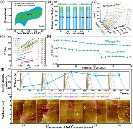
Fig.3 Capacitive contribution marked CV curve at 1 mV s-1 (a), surface capacitance and diffusion-controlled proportion (b), dynamic Nyquist plots at various discharge potentials (c), plots of Z’ vs.ω-1/2 (d) of COFBTMB-TP nanofilms; Li+ diffusion coefficient of COFBTMB-TP nanofilms and powder (e); effect of the concentration of TAPB monomer on the thickness of COFTAPB-BPY nanofilm and energy density of COFTAPB-BPY//COFBTMB-TP nanofilm LIC device (f)
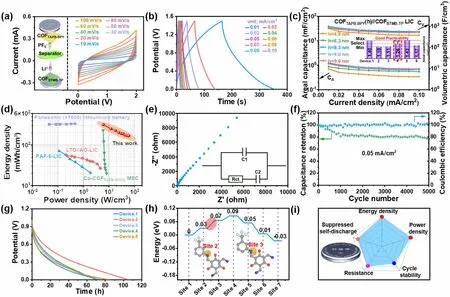
Fig.4 CV (a) and GCD (b) curves, CA and CV (c), Ragone (d) and Nyquist (e) plots, cycle stability and coulombic efficiency (f), self-discharge performance (g) of the COFTAPB-BPY//COFBTMB-TP nanofilm LIC; energy barrier of Li+ diffusion control step in anode COFBTMB-TP structure (h); performance evaluation of COFTAPB-BPY//COFBTMB-TP nanofilm LICs (i)
4 Conclusion
In summary, two free-standing COF nanofilms were synthesized by the reversible Schiff base polymerization on the SDBS surfactant derived gas-liquid interface.The COFBTMB-TPnanofilm, featuring-CF3, C=O, and C-N groups, was assembled into an all-COF nanofilm-structured LIC as the anode and COFTAPB-BPYnanofilm with inherent skeleton nitrogen atoms as the cathode.The strong electronegative-CF3groups can adjust the partial electron cloud density for Li+migration, ensuring the rapid kinetic process of anodic COFBTMB-TPnanofilm, to match the capacitance-type cathodic COFTAPB-BPYnanofilm.The cathodic COFTAPB-BPYnanofilm with the thickness of 8.3 nm can fit the anodic COF nanofilm in the capacity.On basis of both kinetics and capacity balance, the COFTAPB-BPY//COFBTMB-TPnanofilm LIC can exhibit the high volumetric energy density of 318 mWh cm-3at 6 W cm-3, long-cycle stability (77% after 5000 cycles), slow self-discharge, and low resistance.This work provides a new idea for the design of high-performance film-type LIC devices.
AcknowledgementsWe are grateful to National Natural Science Foundation of China (Grant No.22375056, 52272163), the Key R&D Program of Hebei (Grant No.216Z1201G), Natural Science Foundation of Hebei Province (Grant No.E2022208066, B2021208014), and Key R&D Program of Hebei Technological Innovation Center of Chiral Medicine (Grant No.ZXJJ20220105).
Conflict of interestThe authors declare no interest conflict.They have no known competing financial interests or personal relationships that could have appeared to influence the work reported in this paper.
Open AccessThis article is licensed under a Creative Commons Attribution 4.0 International License, which permits use, sharing, adaptation, distribution and reproduction in any medium or format, as long as you give appropriate credit to the original author(s) and the source, provide a link to the Creative Commons licence, and indicate if changes were made.The images or other third party material in this article are included in the article’s Creative Commons licence, unless indicated otherwise in a credit line to the material.If material is not included in the article’s Creative Commons licence and your intended use is not permitted by statutory regulation or exceeds the permitted use, you will need to obtain permission directly from the copyright holder.To view a copy of this licence, visit http:// creat iveco mmons.org/ licen ses/ by/4.0/.
Supplementary InformationThe online version contains supplementary material available at https:// doi.org/ 10.1007/ s40820- 024- 01343-2.
- Nano-Micro Letters的其它文章
- Publisher Correction to: Strongly Coupled 2D Transition Metal Chalcogenide-MXene-Carbonaceous Nanoribbon Heterostructures with Ultrafast Ion Transport for Boosting Sodium/Potassium Ions Storage
- Dual-Atom Nanozyme Eye Drops Attenuate Inflammation and Break the Vicious Cycle in Dry Eye Disease
- The Roadmap of 2D Materials and Devices Toward Chips
- Highly Aligned Graphene Aerogels for Multifunctional Composites
- Thioacetamide Additive Homogenizing Zn Deposition Revealed by In Situ Digital Holography for Advanced Zn Ion Batteries
- Janus Quasi-Solid Electrolyte Membranes with Asymmetric Porous Structure for High-Performance Lithium-Metal Batteries