Effect of icosahedral phase formation on the stress corrosion cracking(SCC) behaviors of the as-cast Mg-8%Li (in wt.%) based alloys
Shuo Wang ,Daokui Xu ,Dongliang Wang ,Zhiqiang Zhang ,Baojie Wang
a Key Lab of Electromagnetic Processing of Materials, Ministry of Education, Northeastern University, Shenyang, 110819, China
b Key Laboratory of Nuclear Materials and Safety Assessment, Institute of Metal Research, Chinese Academy of Sciences, Shenyang, 110016, China
c Engineering Research Center of Advanced Materials Preparing Technology, Ministry of Education, Northeastern University, Shenyang, 110819, China
d School of Environmental and Chemical Engineering, Shenyang Ligong University, Shenyang, 110159, China
e Binzhou Institute of Technology, Binzhou, Shandong Province, 256606, China
fShandong Key Laboratory of Advanced Aluminium Materials and Technology, Binzhou, Shandong Province, 256606, China
Abstract Through exploring the stress corrosion cracking (SCC) behaviors of the as-cast Mg-8%Li and Mg-8%Li-6%Zn-1.2%Y alloys in a 0.1 M NaCl solution,it revealed that the SCC susceptibility index (ISCC) of the Mg-8%Li alloy was 47%,whilst the ISCC of the Mg-8%Li-6%Zn-1.2%Y alloy was 68%.Surface,cross-sectional and fractography observations indicated that for the Mg-8%Li alloy,the α-Mg/β-Li interfaces acted as the preferential crack initiation sites and propagation paths during the SCC process.With regard to the Mg-8%Li-6%Zn-1.2%Y alloy,the crack initiation sites included the I-phase and the interfaces of I-phase/β-Li and α-Mg/β-Li,and the preferential propagation paths were the I-phase/β-Li and α-Mg/β-Li interfaces.Moreover,the SCC of the two alloys was concerned with hydrogen embrittlement (HE)mechanism.
Keywords: Magnesium-lithium alloy;Stress corrosion cracking;I-phase;Fracture analysis.
1.Introduction
As one of the most promising ultra-light metals [1,2],magnesium-lithium (Mg-Li) alloys have the high specific strength,weak mechanical anisotropy,good deformability and high damping resistance,which present great application potential in aerospace,automotive,military applications and electronics [3–8].Generally,Mg-Li alloys with the Li content being lower than 5.5 wt.%,higher than 10.3 wt.% and between 5.5 wt.% ∼10.3 wt.% respectively have the structures of singleα-Mg phase,singleβ-Li phase and duplex(α-Mg +β-Li) phases [6].Compared with the Mg-Li alloys having the single-phase structures,Mg-Li alloys with duplex structure usually present a better match of strength and ductility [7–12].However,the low absolute strength [11–16]and poor corrosion resistance [17–22]could still significantly restrict their widespread applications.In the past few years,Xu et al.[12]have reported that by adding elements Zn and Y(the atomic ratio of Zn/Y was kept of 6) into the duplex structured Mg-Li alloys,the in-situ formation of quasicrystal icosahedral phase (I-phase,Mg3Zn6Y) can markedly improve their tensile strengths [12].Moreover,previous work reported that the formed I-phase in the Mg-6%Li-6%Zn-1.2%Y alloy could act as the barriers to prevent the development of pitting[16].Therefore,it can be deduced that the service properties of Mg-Li alloys can be promoted due to the I-phase formation.
However,in the real service environment,the applied stress and corrosive media can often coexist.Due to their interactions,metallic materials can usually undergo the risk of stress corrosion cracking (SCC) [23–39].The occurrence of SCC is extremely complicated and dangerous,which could cause the sudden fracture and even lead to disastrous accidents [32,33].Similarly,the SCC is also one of the failure risks of Mg-Li based alloys.Therefore,the investigation to SCC behaviors is crucial for guaranteeing their service security in the engineering fields.However,so far,few correlative researches about the SCC behaviors of Mg-Li based alloys could be directly referred.In previous work,investigations mainly concentrated on the SCC behaviors of traditional Mg alloys [23–39].For Mg alloys,the occurrence of SCC is concerned with anodic dissolution (AD) [24,32,33]or hydrogen embrittlement (HE)mechanisms [25–39].Kannan et al.[24]reported that for the ZE41 Mg alloy,the SCC was owing to the intergranular corrosion induced by the continuously precipitated secondary phases at grain boundaries.Moreover,the fracture surface exhibited a large number of intergranular corrosion features and intergranular cracks [24].Winzer et al.[33]reported that during the SCC processes of Mg alloys,cracks could initiate at the bottom of pits due to the stress concentration.Besides,since the anodic dissolution ofα-Mg matrix in corrosive environment is inevitable accompanied by the cathodic hydrogen evolution,the SCC processes of Mg alloys are always associated with HE [25–39].Generally,the preferential sites of HE occurrence in Mg alloys are mainly ascribed to the cathodic secondary phase [26,28,31,34,35],localized corrosion [25,30,36],phase interface [26,28]and grain boundary[25,39].Moreover,the sites of HE occurrence could preferentially result in the crack initiation of Mg alloys [25-31,34-39].Wang et al.[26]reported that during the SCC process of a Mg-Gd-Y-Nd-Zr alloy,hydrogen atoms could accumulate and penetrate into the interior of the secondary phases.The penetrated hydrogen atoms can weaken the atomic bonding of the secondary phases or/and combine with them to form the brittle hydrides [26],resulting in the preferential cracking of secondary phases under the applied stress.Similarly,for the AZ91 alloy,the SCC failure was concerned with the brittle cracking of the hydrides formed in secondary phases [35].Zhou et al.[36]revealed that for the ZK60 alloy,the localized corrosion being formed during the SCC process could be helpful for the penetration of hydrogen atoms into theα-Mg matrix.After that,the hydrogen-induced cracking could occur at the low surface energy crystallographic planes (i.e.{0001},{10–11},{10–10},{1–101} and {31–40}) of theα-Mg matrix [36].Besides,theα-Mg/secondary phase interfaces and the grain boundaries could act as hydrogen traps and subsequently crack initiation sites during the SCC processes [25,26,28,39].Regardless of the mechanisms (AD or HE),the occurrence of SCC in Mg alloys could always cause their sharp decrease of elongation ratios [24–39].Therefore,in order to improve their SCC resistance,the tendency of AD or HE should be reduced [32,33].For Mg alloys,the amount of the evolved hydrogen is associated with the corrosion severity [40–43].Thus,through weakening the corrosion damage of theα-Mg matrix,the SCC resistance can be efficiently enhanced [25,26].
Since the corrosion processes of Mg-Li based alloys were accompanied by cathodic hydrogen evolution reaction [6,17-19],the SCC behaviors of the duplex structured Mg-Li and the I-phase contained Mg-Li-Zn-Y alloys could also be concerned with AD or HE mechanisms.However,so far,it is still unknown that which mechanism is more suitable for explaining the SCC of Mg-Li based alloys.Additionally,whatever the suitable mechanism is,it is necessary to reveal the preferential crack initiation sites during the SCC processes.The theoretical crack initiation sites of the duplex structured Mg-Li alloys could contain theα-Mg,β-Li orα-Mg/β-Li interface.Previous study reported that for the duplex structured Mg-Li alloys being immersed in NaCl solution,the localized corrosion could preferentially occur in theα-Mg phase,whilst theβ-Li phase was almost uncorroded due to the formed dense Li2CO3films [6,18,19].Theoretically,the corrodedα-Mg phase may act as the stress concentration site [33]or/and the site of HE occurrence [25,30,33,36]and cause the subsequent cracking during the SCC processes[25,30,33,36].However,the corrosion films on the surfaces of Mg-based alloys can be broken by the local ductile deformation during the SCC processes [33].Once the corrosion films formed on the surfaces of the duplex structured Mg-Li alloys is broken during the SCC processes,the corrosion performance of the two matrix phases and the preferential sites for HE occurrence will be changed.Besides the two matrix phases,their interfaces can serve as the interfacial corrosion area[21,24]or/and hydrogen trap [26,28].Therefore,during the SCC processes,cracks could also initiate at theα-Mg/β-Li interface owing to the interfacial corrosion or/and HE.In cases of the I-phase contained Mg-Li-Zn-Y alloys,it was demonstrated that the formed I-phase could alleviate the corrosion attack of the alloy matrix [17].Moreover,Wang et al.[25]found that during the SCC process of an I-phase contained Mg-Zn-Y-Zr alloy,I-phase did not serve as the preferential HE occurrence site.Following this,the in-situ formation of I-phase in the duplex structured Mg-Li alloys could be a promising method for promoting the SCC resistance.However,the I-phase was brittle and could be preferentially cracked during the tensile testing[9,11,12].Once the I-phase is broken during the SCC process,its protectiveness to corrosion will be degraded.Thus,whether the degraded I-phase could promote the SCC resistance or not,it needs further investigation.Moreover,compared with theα-Mg andβ-Li phases,I-phase has a higher corrosion potential [17].Therefore,both the corrosion behavior and the preferential sites for HE occurrence of the I-phase contained Mg-Li-Zn-Y alloys could be inconsistent with those of the Mg-Li alloys [17].Meanwhile,when the I-phase is in-situ formed,a lot of I-phase/α-Mg and I-phase/β-Li interfaces will be created [9–12],which increases the number of interfacial corrosion areas [21,24]and hydrogen traps [26,28]and further affects the SCC behavior of the duplex structured Mg-Li alloys.
Based on the above descriptions,three questions can be raised: (1) For the AD or HE mechanisms,which one is more suitable for explaining the SCC behaviors of the duplex structured Mg-Li and the I-phase contained Mg-Li-Zn-Y alloys? (2) For theα-Mg,β-Li orα-Mg/β-Li interface,which one can serve as the preferential crack initiation site during the SCC process? (3) How does the formed I-phase affect the SCC of the duplex structured Mg-Li alloys? In this work,through exploring and comparing the SCC behaviors of the as-cast Mg-8%Li and Mg-8%Li-6%Zn-1.2%Y (all in wt.%) alloys,the above questions will be answered.Moreover,the specific mechanisms for inducing the different SCC performances of two alloys are disclosed.
2.Materials and experimental methods
The experimental materials were the as-cast Mg-8%Li and Mg-8%Li-6%Zn-1.2%Y alloys.The ingots were prepared in a vacuum furnace and then preserved at 400 °C for 2 h in a heat treatment furnace to homogenize the microstructures.After that,their chemical compositions were measured by using inductively coupled plasma atomic emission spectroscopy(ICP-AES) apparatus,and the results were listed in Table 1.Besides,in order to disclose the phase compositions of two alloys,X-ray diffractometer (XRD;D/Max 2400) analysis was adopted.For the microstructural observations,the scanning electron microscopy (SEM;EmCrafts CUBE II) was used.

Table 1 Chemical composition of the as-cast Mg-8%Li and Mg-8%Li-6%Zn-1.2%Y alloys.
The SCC behaviors of two alloys were explored by using slow strain rate tensile (SSRT) testing.The experimental samples were the fishbone shape plates with the gauge section size of 25 mm×4 mm×3 mm processed from the ingots.Before the tests,samples were grinded and polished.Then,the SSRT testing was carried out on a mechanical property testing machine (Care,IBTC-5000) at the applied strain rate of 1 ×10⁻⁵s-1in air and in a 0.1 M NaCl solution,respectively.The rate was selected on the basis of ASTM G129-00.Among them,the NaCl solution was contained in an environmental cell that was set up on the gauge section.Through a water pump,the solution was circulated inside/outside the environmental cell from a water box with the volume of 10 L and the flow rate was controlled to be about 100 mL/min.During the SSRT testing,an extensometer was connected with the gauge section and outside the environmental cell to record the accurate tensile-strains curves.Moreover,to clearly characterize and compare the microstructural evolutions of two alloys during the SCC processes,the morphologies of the surface being applied different tensile strains in the NaCl solution were insitu observed by an optical microscopy (OM;Keyence VHX-900F).After the SSRT testing,the SCC-failed samples were immersed in a 180 g/L CrO3hot chromic acid solution for 300 s to remove the surface corrosion products.To disclose the crack initiation and propagation,cross-sections perpendicular to the tensile direction were cut.Then,the surfaces,cross-sections and fracture surfaces were observed by SEM.
3.Results
3.1. Microstructural characterization
As shown in Fig.1,the XRD results reveal that the Mg-8%Li alloy is composed ofα-Mg andβ-Li phases,whereas the Mg-8%Li-6%Zn-1.2%Y alloy is mainly consisted ofα-Mg,β-Li,I-phase and W-phase (Mg3Zn2Y2).In general,for the Mg-Li-Zn-Y alloys having the Zn/Y weight percent ratio higher than 4.38,element Y would primarily exist in the form of I-phase and the W-phase can be hardly formed [9].However,owing to the nonequilibrium solidification during the casting process,a small amount of W-phase can also present in the Mg-8%Li-6%Zn-1.2%Y alloy [9].The peak intensity of I-phase is much higher than that of the W-phase,indicating that the quantity of W-phase in the Mg-8%Li-6%Zn-1.2%Y alloy is much less than that of the I-phase.Fig.2 is the SEM observation to the microstructure.It shows that the Mg-8%Li alloy is consisted of whiteα-Mg phase and darkβ-Li phase(Fig.2(a)).In term of the Mg-8%Li-6%Zn-1.2%Y alloy,obvious I-phase is formed and distributes in the interior ofα-Mg andβ-Li phases and at theα-Mg/β-Li interfaces (Fig.2(b)).Moreover,the W-phase is preferentially coexisted with the I-phase.Similar results have been reported in the previous works [17,44].Besides the I-phase and W-phase,some finely dispersed precipitates can be observed inside theβ-Li phase.It was reported that these precipitates were the fineα-Mg and MgLiZn particles formed during the natural ageing processes[9].However,since the MgLiZn particles are very small,they can hardly be detected by XRD.
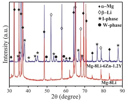
Fig.1.XRD phase analysis diagrams of the Mg-8%Li and Mg-8%Li-6%Zn-1.2%Y alloys.
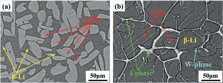
Fig.2.Scanning electron microscopy (SEM) observations to the as-polished surfaces of: (a) Mg-8%Li and (b) Mg-8%Li-6%Zn-1.2%Y alloys in the backscattered eletron mode.
3.2. Slow strain rate tensile testing
Fig.3 illustrates the differently tested stress-strain curves.The determined yield strength (σ0.2),ultimate strength (UTS)and elongation ratio to failure(εf)values are listed in Table 2.It reveals that the values ofσ0.2,UTS andεfof the Mg-8%Li alloy tested in air are respectively 62 MPa,68 MPa and 77%,whilst those of the Mg-8%Li-6%Zn-1.2%Y alloy are 91 MPa,108 MPa and 48%.It can be seen that the I-phase is beneficial to the strength improvement but harmful to the ductility,which is in accordance with the previous works[9–11].However,it should be noted that the measuredσ0.2and UTS values of two alloys are relatively lower than those reported in the previous works [11].This is because the mechanical behaviors of the Mg-Li based alloys are very susceptible to the strain rate [45].Takuda et al.[45]reported that with the strain rate decreasing,theσ0.2and UTS of the duplex structured Mg-8.5Li-1Zn alloy gradually was decreased,whilst the ductility was increased.Since the applied strain rate in this study is 1×10⁻⁵s-1,the measured values in this study are reasonable.For the SCC-failed samples,theεfvalues are remarkably reduced in comparison with those failed in air.Theσ0.2,UTS andεfof Mg-8%Li alloy are decreased to 57 MPa,62 MPa and 41%.In case of Mg-8%Li-6%Zn-1.2%Y alloy,theσ0.2and UTS values are slightly decreased to 83 MPa and 104 MPa.However,theεfis sharply decreased from 48% to 15%.On the basis of the loss of elongation ratios,the SCC susceptibility index (ISCC)values of Mg alloys are calculated from Eq.(1) [24–26]:
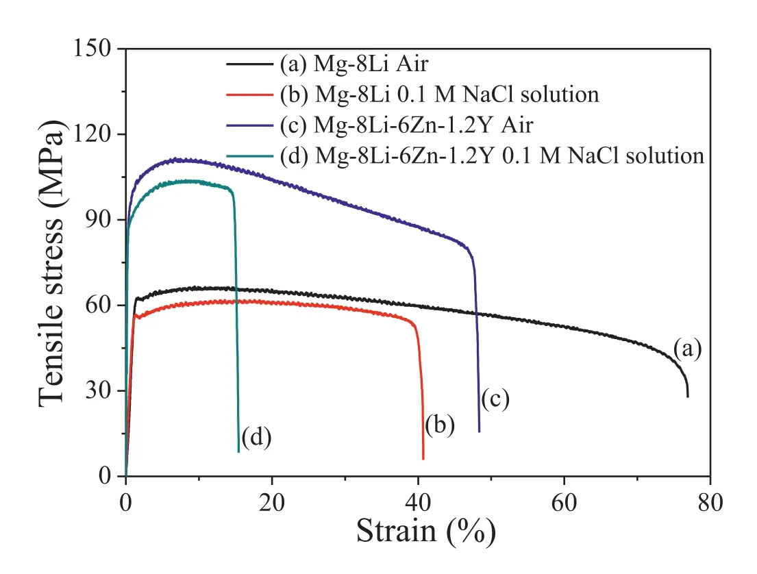
Fig.3.Slow strain rate tensile (SSRT) curves of Mg-8%Li and Mg-8%Li-6%Zn-1.2%Y alloys tested in air and in a 0.1 M NaCl solution.

Table 2 Mechanical properties of Mg-8%Li and Mg-8%Li-6%Zn-1.2%Y alloys.
Theεsolandεairare respectively theεfvalues measured in the corrosive media and in air.In general,the alloy with theISCCclose to 1 has a high susceptibility to SCC.According to the calculated results,theISCCvalues of the Mg-8%Li and Mg-8%Li-6%Zn-1.2%Y alloys are respectively 47% and 68%,indicating that the SCC resistance of Mg-8%Li alloy is lower than that of Mg-8%Li-6%Zn-1.2%Y alloy.
3.3. In-situ observations to the SCC processes
The in-situ observations to the SCC processes of two alloys are respectively shown in Figs.4 and 5.For the Mg-8%Li alloy,obvious localized corrosion occurs in the interior of theβ-Li phase after the applied strain being reached 2% (Fig.4(b)).Meanwhile,bubbles can be formed on the tips of the filiform-like corrosion.When the applied strain is reached 3%,the localized corrosion gradually develops into theα-Mg phase (Fig.4(c)),resulting in the increase of the corroded area.With the applied strain being reached 5%,the corrosion attack onα-Mg phase is further worsened but still weaker than that onβ-Li phase (Fig.4(d)).Additionally,for the unstrained Mg-8%Li sample,the contrast between the two phases is very clear.However,the difference in their contrast decreases during the SSRT testing,which is mainly due to the formation of surface corrosion films during the SCC process.For the Mg-8%Li-6%Zn-1.2%Y alloy,the localized corrosion occurs in both the two matrix phases when the applied strain is reached 2% (Fig.5(b)).With the tensile strain being reached 3% and 5%,the corrosion severity continuously increases and the localized corrosion preferentially occurs in two matrix phases (Fig.5(c) and (d)).
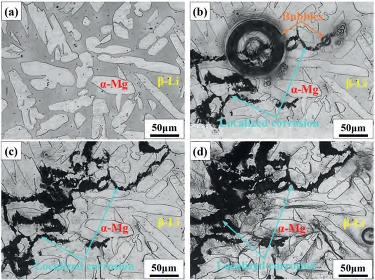
Fig.4.Surface morphologies of the Mg-8%Li alloy being performed SSRT testing in a 0.1 M NaCl solution for different strains of: (a) 0%,(b) 2%,(c) 3%and (d) 5%.

Fig.5.Surface morphologies of the Mg-8%Li-6%Zn-1.2%Y alloy being performed SSRT testing in a 0.1 M NaCl solution for different strains of: (a) 0%,(b) 2%,(c) 3% and (d) 5%.
3.4. Surface and cross-sectional morphologies
The low and high magnification observations to the surfaces of two alloys failed in air and in a 0.1 M NaCl solution are shown in Fig.6.It reveals that the overall side fracture surfaces of the alloys failed in air exhibit significant necking and have the typical characteristics of ductile (Fig.6(a) and(c)).For the samples being failed in the NaCl solution,the side fracture surfaces are relative flat and have the typical feature of brittle fracture (Fig.6(e) and (g)).High-magnified observation to the Mg-8%Li alloy failed in air reveals that obvious slip bands are formed inside the two matrix phases(Fig.6(b)).Moreover,secondary cracks preferentially initiate along the slip bands and at theα-Mg/β-Li interfaces.For the Mg-8%Li-6%Zn-1.2%Y alloy failed in air,it shows that although slip bands are formed inside the two matrix phases,the I-phase andα-Mg/β-Li interfaces are preferentially cracked(Fig.6(d)).With regard to the SCC-failed Mg-8%Li alloy,the preferential localized corrosion area is theβ-Li phase(Fig.6(f)).In the meantime,secondary cracks could be seen in the interior of the pits and at theα-Mg/β-Li interfaces.For the SCC-failed Mg-8%Li-6%Zn-1.2%Y alloy,both theα-Mg andβ-Li phases are corroded (Fig.6(h)).Moreover,the preferential cracking sites includes the I-phase,the corrosion pits and the I-phase/matrix interfaces.
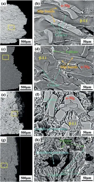
Fig.6.Scanning electron microscopy(SEM)observations to the surface morphologies near to the fracture surfaces of failed samples: images (a,e) and(c,g) are respectively the low-magnified morphologies of Mg-8%Li and Mg-8%Li-6%Zn-1.2%Y alloys tested in air and in a 0.1 M NaCl solution.Images(b),(d),(f) and (h) are respectively the high-magnified morphologies of the squared areas in images (a),(c),(e) and (g).
Fig.7 shows the cross-sectional morphologies of two SCC failed alloys.For the Mg-8%Li alloy,short cracks with the size less than 50 μm can be observed to initiate at theα-Mg/β-Li interfaces (Fig.7(a) and (b)) when the cross-section is 4 mm from the fracture site.Meanwhile,the localized corrosion preferentially occurs in the interior ofβ-Li phase,but no cracks could be seen at the bottom of the pits,which is different from the observed results on the surface (Fig.6(c)).It indicates that the cracks on the corroded surface ofβ-Li phase could be actually attributed to the cracking of remaining corrosion products [33].Moreover,there are also no cracks formed in theα-Mg phase.When the cross-section is 2 mm from the fracture site,long cracks with the size larger than 500 μm can be observed.Moreover,the preferential propagation paths are along theα-Mg/β-Li interfaces (Fig.7(c) and(d)).For the Mg-8%Li-6%Zn-1.2%Y alloy,when the crosssection is 3 mm from the fracture site,short cracks with the size less than 20 μm can be observed to initiate in the interior of I-phase and at the interfaces of I-phase/β-Li andα-Mg/β-Li (Fig.7(e) and (f)).When the cross-section is 2 mm from the fracture site,long cracks with the size larger than 500 μm are formed along the interfaces of I-phase/β-Li andα-Mg/β-Li (Fig.7(g) and (h)).Moreover,the localized corrosion occurs in both the two matrix phases,and no cracks are formed at the bottom of the pits.
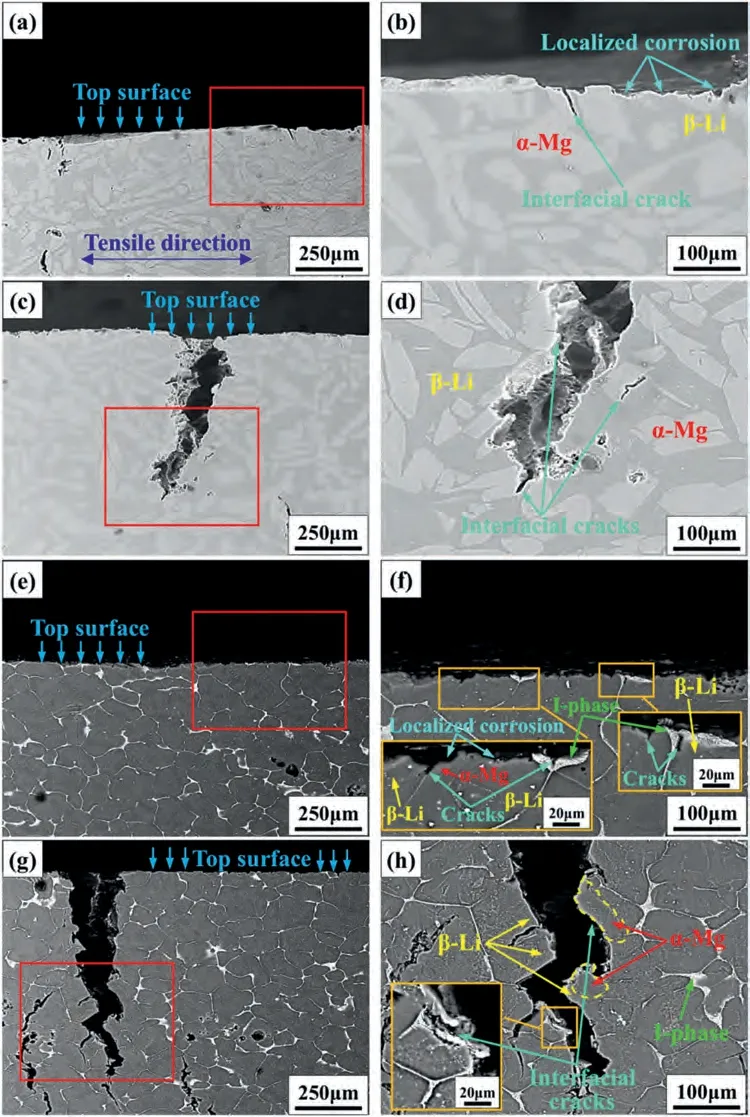
Fig.7.Scanning electron microscopy (SEM) observations to cross-sectional morphologies of the SCC-failed samples: images (a,e) and (c,g) are respectively the low-magnified morphologies of the areas far away from and near to the fracture surface of Mg-8%Li and Mg-8%Li-6%Zn-1.2%Y alloys.Images (b),(d),(f) and (h) are respectively the high-magnified morphologies of the squared areas in images (a),(c),(e) and (g).
3.5. Fractography
Fig.8 exhibits the overall fracture surfaces of differently tested samples.It shows that the samples failed in air have rough fracture surfaces,whilst the fractures of the samples failed in NaCl solution are relatively flat.The phenomenon indicates that the alloys tend to be ductile in air and brittle in solution.To further disclose and compare the SCC mechanisms of two alloys,high-magnified observations to the fracture surfaces are shown in Fig.9.It can be seen that the fractures of two alloys tested in air are consisted of dimples,which further proves the occurrence of ductile fracture (Fig.9(a)and (b)).Moreover,for the Mg-8%Li-6%Zn-1.2%Y alloy,the cracked I-phase is located at the bottom of the dimple,demonstrating that the I-phase is cracked during the tensile process(Fig.9(b)).In terms of the samples failed in the NaCl solution,their fracture surfaces exhibit the typical brittle fractured characteristics (Fig.9(c-f)).On the fracture edges of two alloys,the localized corrosion could be seen (Fig.9(c) and (d)).For the Mg-8%Li-6%Zn-1.2%Y alloy,the maximum depth of the pits is about 80 μm (Fig.9(d)) and is much deeper than that of the Mg-8%Li alloy (about 25 μm) (Fig.9(c)).Moreover,the cracked I-phase is located near the pits.For both two alloys,no obvious cracks are formed at the bottom of pits.For the SCC-failed Mg-8%Li alloy,besides the localized corrosion,theα-Mg/β-Li interfacial cracks are formed in both the edge and center of the fracture (Fig.9(c) and (e)).For the SCC-failed Mg-8%Li-6%Zn-1.2%Y alloy,interfacial cracks are located at the I-phase/matrix andα-Mg/β-Li interfaces(Fig.9(d) and (f)).Although obvious interfacial cracks can be seen on the fractures of the SCC-failed samples,no corrosion features are formed along the phase interfaces.Therefore,it can be inferred that the initiation and propagation of the cracks should be irrelated to the interfacial corrosion.
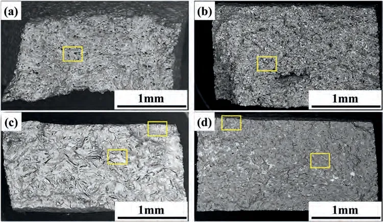
Fig.8.Overall fracture surfaces of the differently failed samples: (a) and (b) are Mg-8%Li and Mg-8%Li-6%Zn-1.2%Y alloys failed in air,(c) and (d) are Mg-8%Li and Mg-8%Li-6%Zn-1.2%Y alloys failed in a 0.1 M NaCl solution.
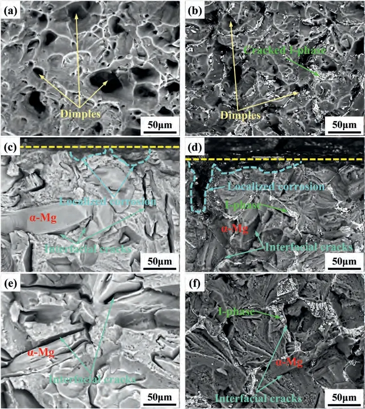
Fig.9.High-magnified observations to fracture surfaces of the differently failed samples: Images (a) and (b) are the Mg-8%Li and Mg-8%Li-6%Zn-1.2%Y alloys failed in air,images (c-f) are the edge and centre morphologies of the Mg-8%Li and Mg-8%Li-6%Zn-1.2%Y alloys failed in a 0.1 M NaCl solution,respectively.Images (a-f) are respectively squared in Fig.8(a-d).
4.Discussion
In order to better disclose and compare the SCC mechanisms of two alloys,schematic diagrams for reflecting their SCC processes are proposed,as shown in Fig.10.For the two alloys,the SCC processes contain three stages,i.e.crack initiation,propagation and final fracture of the samples.For the Mg-8%Li alloy,the localized corrosion occurs in the interior of theβ-Li phase at the initial stage of SCC,as shown Fig.4.Interestingly,previous works reported that when the duplex structured Mg-Li alloys were immersed in NaCl solution,the localized corrosion preferentially occurred in theα-Mg phase,whilst theβ-Li phase was almost uncorroded owing to the compact Li2CO3films formed on it [6,18,19],which was different from the observed results in Fig.4.The possible explanation is that due to the locally plastic deformation during the SSRT process,the surface film formed on the alloys could be degraded [33].After that,the freshα-Mg andβ-Li matrix phases could be simultaneously exposed to the corrosive media.It has been reported that for the Mg-8%Li alloy,the corrosion potential of theα-Mg phase was about 0.3 VSCEhigher than that of theβ-Li phase [46].Therefore,in this work,β-Li phase is preferentially anodic dissolved during the SCC process of the Mg-8%Li alloy.However,the cross-sectional morphology shows that no cracks are formed at the bottom of the corrodedβ-Li phase (Fig.7(b)),which indicates that the pits are not the initiation sites of SCC.Moreover,the fractography shows that for the SCC-failed Mg-8%Li alloy,no obvious interfacial corrosion features can be observed (Fig.9(c)and (e)).Therefore,the SCC of the Mg-8%Li alloy is closely related to the HE mechanism [6,17-19].Based on the crosssectional morphology,it can be seen that for the SCC-failed Mg-8%Li alloy,the preferential crack initiation site is theα-Mg/β-Li interface rather than the localized corrosion area (β-Li phase) or the cathode (α-Mg phase) (Fig.7(b)).This phenomenon can be explained by hydrogen trap theory [47–49].Generally,for the duplex structured metallic materials,phase interfaces being as the hydrogen trapping sites could capture more hydrogen atoms than the matrix [47–49].Similarly,theα-Mg/secondary phase interfaces in Mg alloys could also act as hydrogen traps [26,28].Therefore,during the SCC process of the Mg-8%Li alloy,the evolved hydrogen could be preferentially captured and accumulate at theα-Mg/β-Li interfaces in the forms of hydrogen atoms or hydrides [26,28,37].It has been reported that the hydrogen atoms caused the degradation of the atomic bonding energy,whilst the formed hydride was brittle [37].Thus,theα-Mg/β-Li interfaces in Mg-8%Li alloy preferentially act as the crack initiation sites during the SCC process (Fig.10(b)).At the second stage of SCC,more hydrogen atoms could penetrate into the matrix and accumulate at theα-Mg/β-Li interfaces,resulting in the further degradation of interfacial bonding strength.Thus,cracks will preferentially propagate along the phase interfaces during the subsequent SSRT process (Fig.10(c)).At the final stage,the interfacial cracks could coalesce with each other and cause the final fracture of the whole sample (Fig.10(d)).
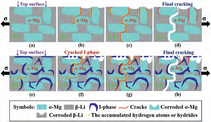
Fig.10.Schematic diagrams of the SCC processes for two alloys: (a) initial microstructure,(b) crack initiation,(c) crack propagation and (d) final fracture of the Mg-8%Li alloy;(e) initial microstructure,(f) crack initiation,(g) crack propagation and (h) final fracture of the Mg-8%Li-6%Zn-1.2%Y alloy.
Fig.10(e-h) shows the SCC process of the Mg-8%Li-6%Zn-1.2%Y alloy.It reveals that the cracks preferentially initiate in the interior of the I-phase/matrix eutectic pockets or at the interfaces of I-phase/β-Li andα-Mg/β-Li (Figs.7(f)and 10(f)),whilst no cracks are formed at the bottom of the pits (Fig.7(f)).Moreover,the fractography of the SCC-failed Mg-8%Li-6%Zn-1.2%Y alloy manifests that no obvious interfacial corrosion occurs (Fig.9(d) and (f)).Thus,it can be inferred that the main mechanism for causing the SCC of the Mg-8%Li-6%Zn-1.2%Y alloy is more likely to be HE rather than AD.Previous work reported that for an I-phase contained Mg-Zn-Y-Zr alloy,I-phase did not serve as the preferential site of HE occurrence [25].Moreover,for the I-phase contained duplex structured Mg-Li-Zn-Y alloys,I-phase was more brittle than the two matrix phases [9,11,12].Thus,when the applied plastic strain that exceeds the endurance limit of the I-phase [12],the cracking of the I-phase occurs.Generally,the intact I-phase/matrix eutectic pockets can hinder the development of corrosion pits [17].However,after being broken,their protectiveness to corrosion attack will be degraded.Furthermore,it has been reported that for the I-phase contained duplex structured Mg-Li-Zn-Y alloys,I-phase has a higher corrosion potential than those of theα-Mg andβ-Li phases and can act as the cathode in corrosive media [17].Thus,being as the anodes,the two matrix phases near the cracked I-phase will be preferentially dissolved.Meanwhile,the cracked I-phase can act as the cathode and promote the galvanic corrosion,resulting in the increased corrosion rate[17,26].For the Mg-Li based alloys,the hydrogen evolved rates are basically proportional to the corrosion rates [17–19].Therefore,it can be inferred that the hydrogen evolved rate of the Mg-8%Li-6%Zn-1.2%Y alloy is much higher than that of Mg-8%Li alloy during the SCC processes.Besides,the preferential hydrogen trapped sites of Mg-8%Li-6%Zn-1.2%Y alloy could contain the interfaces of I-phase/α-Mg,I-phase/β-Li andα-Mg/β-Li.However,the cross-sectional morphologies of SCC-failed sample reveal that the cracks preferentially initiate at the interfaces of I-phase/β-Li andα-Mg/β-Li,whilst no cracks can be observed at the I-phase/α-Mg interfaces(Fig.7(f)).The main reason is that theα-Mg and I-phase can have a semi-coherence relationship and their interfacial bonding energy is strong [50].At the second stage,more hydrogen atoms could be evolved and accumulate at the interfaces of the I-phase/matrix andα-Mg/β-Li.With the applied tensile stress being gradually increased,the I-phase/β-Li andα-Mg/β-Li interfaces will be destroyed and act as the crack propagation paths (Fig.10(g)).At the final stage,these interfacial cracks merge with each other and cause the final fracture of the whole sample (Fig.10(h)).Theoretically,the formed W-phase could also affect the SCC of the Mg-8%Li-6%Zn-1.2%Y alloy.It has been reported that the corrosion potential of W-phase is higher than those of theα-Mg andβ-Li phases [43,46].Moreover,W-phase is brittle and can be easily cracked during the SCC process [51].Similar to the I-phase,the cracked W-phase should be also act as the cathode and then accelerate the hydrogen evolution rate of the alloy.Meanwhile,the W-phase/matrix interfaces can serve as the hydrogen traps [26,28].Therefore,the formation of the W-phase in Mg-8%Li-6%Zn-1.2%Y alloy should have the similar effect of I-phase on the degradation of SCC resistance.However,based on the results of XRD analysis (Fig.1)and SEM observation (Fig.2),the quantity and size of Wphase in Mg-8%Li-6%Zn-1.2%Y alloy are much smaller than those of the I-phase.Moreover,the cross-sectional observations (Fig.7(e-g)) also indicates that the SCC of Mg-8%Li-6%Zn-1.2%Y alloy is mainly related to the I-phase.Therefore,it can be deduced that the influence of W-phase on SCC could be omitted.
5.Conclusions
Through performing SSRT,the SCC behaviors of the ascast Mg-8%Li and Mg-8%Li-6%Zn-1.2%Y alloys were explored and compared.The main conclusions are drawn as follows:
1) TheISCCof the Mg-8%Li alloy was 47%,whilst that of the Mg-8%Li-6%Zn-1.2%Y alloy was 68%.The insitu formed I-phase degraded the SCC resistance of the Mg-8%Li-6%Zn-1.2%Y alloy.
2) During the SCC process of the Mg-8%Li alloy,the localized corrosion preferentially occurs in the interior ofβ-Li phase.For the Mg-8%Li-6%Zn-1.2%Y alloy,the localized corrosion occurs in bothα-Mg andβ-Li phases.
3) The preferential crack initiation sites and propagation paths of the Mg-8%Li alloy were theα-Mg/β-Li interfaces.For the Mg-8%Li-6%Zn-1.2%Y alloy,the main crack initiation sites included the interior of I-phase and the interfaces of I-phase/β-Li andα-Mg/β-Li.Moreover,the preferential crack propagation paths were along the I-phase/β-Li andα-Mg/β-Li interfaces.
Declaration of competing interest
None.
Acknowledgements
This work was supported by the National Natural Science Foundation of China Projects under Grant [Nos.51871211,U21A2049,52071220,51701129 and 51971054],Liaoning Province’s project of “Revitalizing Liaoning Talents”(XLYC1907062),the Doctor Startup Fund of Natural Science Foundation Program of Liaoning Province (No.2019-BS-200),the Strategic New Industry Development Special Foundation of Shenzhen (JCYJ20170306141749970),the funds of International Joint Laboratory for Light Alloys,Liaoning BaiQianWan Talents Program,the Domain Foundation of Equipment Advance Research of 13th Five-year Plan(61409220118),National Key Research and Development Program of China under Grant [Nos.2017YFB0702001 and 2016YFB0301105],the Innovation Fund of Institute of Metal Research (IMR),Chinese Academy of Sciences (CAS),the National Basic Research Program of China (973 Program)project under Grant No.2013CB632205,and the Fundamental Research Fund for the Central Universities under Grant [No.N2009006].Bintech-IMR R&D Program [No.GYY-JSBU-2022-009].
 Journal of Magnesium and Alloys2024年1期
- Journal of Magnesium and Alloys的其它文章
- Graphene–calcium carbonate coating to improve the degradation resistance and mechanical integrity of a biodegradable implant
- Degradable magnesium alloy suture promotes fibrocartilaginous interface regeneration in a rat rotator cuff transosseous repair model
- Stress-corrosion coupled damage localization induced by secondary phases in bio-degradable Mg alloys: phase-field modeling
- HVOF-sprayed HAp/S53P4 BG composite coatings on an AZ31 alloy for potential applications in temporary implants
- Greatly enhanced corrosion/wear resistances of epoxy coating for Mg alloy through a synergistic effect between functionalized graphene and insulated blocking layer
- Superplasticity of fine-grained Mg-10Li alloy prepared by severe plastic deformation and understanding its deformation mechanisms
