Microfluidic separation of particles by synergistic effect ofgeometry-induced hydrodynamics and magnetic field
Du Qio ,Hongxi Li,* ,Weiping Zhu ,Lili Zhu ,Dnyng Zho ,Honglin Li,c
a Key Laboratory for Precision & Non-traditional Machining Technology of Ministry of Education,Dalian University of Technology,Dalian 116023,China
b Shanghai Key Laboratory of New Drug Design,School of Pharmacy,East China University of Science and Technology,Shanghai 200237,China
c Lingang Lab,Shanghai 200031,China
Keywords: Microfluidic Particle separation Synergistic effect Hydrodynamics Magnetic field Numerical calculation
ABSTRACT Microfluidic combined with magnetic field have been demonstrated to be the promising solutions for fast and low-damage particles separation.However,the difficulties in the precise layout of magnets and accurate prediction of particle trajectories lead to under and over separation of target particles.A novel particle separation lab-on-chip (LOC) prototype integrated with microstructures and micropolar arrays is designed and characterized.Meanwhile,a numerical model for the separation of magnetic particles by the synergistic effect of geometry-induced hydrodynamics and magnetic field is constructed.The effect of geometry and magnetic field layout on particle deflection is systematically analyzed to implement accurate prediction of particle trajectories.It is found that the separation efficiency of magnetic particles increased from 50.2% to 91.7% and decreased from 88.6% to 85.7% in the range of depth factors from 15 μm to 27 μm and width factors from 30 μm to 60 μm,respectively.In particular,the combined effect of the offset distance of permanent magnets and the distance from the main flow channel exhibits a significant difference from the conventional perception.Finally,the developed LOC prototype was generalized for extension to arbitrary systems.This work provides a new insight and robust method for the microfluidic separation of magnetic particles.
Precise separation of bioparticles from complex biofluids has been a landmark in the development of modern biological and medical applications,with rapidly expanding demand to date for de-laboratoryization in areas such as CAR-T cell immunotherapy[1],exosome-based disease diagnosis [2],and circulating tumor cell (CTC) enrichment [3].Recently,lab-on-chip (LOC) combined with microfluidic has shown potential for cell and particle separation [4-8] as an alternative to manual execution with high precision and efficiency.Meanwhile,active and passive microfluidic methods based on different dynamic mechanisms have been developed for the physical and biological properties of the target particles.
Passive methods mostly achieve particle size-based separations using hydrodynamic effects induced by the geometric characteristics of microfluidic channels in LOC [9-12],such as hydrodynamic focusing [13,14],inertial migration [15,16],and deterministic lateral displacement [17].Geometry-induced hydrodynamic effects provide a simple solution for the separation of target particles.However,the inherent drawbacks of the hydrodynamics-induced particle attachment and low flexibility make it difficult to precisely manipulate the separation process and limit effective separation.As a complement to passive methods,active microfluidic separation [18-20] allows for more flexible control of motion paths to achieve separation process based on target particle biochemistry.In particular,the magnetic field-based operation provides an effi-cient way to separate particles without injury [21].Combining permanent magnets directly with the microfluidic channel by external connection [22-24] is the simplest implementation.Nevertheless,the complexity and sensitivity of the magnetophoretic system makes it difficult to find a balance between multi-impact factors,which leads to over and under deflection of target particles.Besides,manual adjustment of the permanent magnet distribution is unable to accurately predict the particle motion path,resulting in difficult and inefficient particle separation operations.There is no doubt that the layout of permanent magnets and the prediction of particle paths are essential for effective and accurate microfluidic particle separation.
The constitutive equation of magnetic particle transport [25] is one of the effective approaches to the above problem,but it seems difficult to extend to magnetophoretic systems with arbitrary geometrical coupling due to the lack of magnetic field variation and hydrodynamic considerations so far.Multi-physics field computational modeling based on real systems demonstrates potential for magnetophoretic particle dynamics prediction [26-28].Outokeshetal.[29] proposed that particle multi-process sorting and enrichment be integrated into a numerical model for predicting the trajectories of particles inside droplets.Abhisheketal.[30] performed simultaneous separation operations on two different types of magnetic particles in a free-flow microchannel and numerically investigated the effects of operating parameters on particle separation and capture in a magnetophoretic system.Jiaetal.[31] proposed the use of curved comb structure combined with magnetophoresis technique to achieve size-based separation of magnetic particles.Although numerous useful results have been obtained in magnetophoretic separation of magnetic particles,most interest has focused on particle size-based manipulations.Considerably less attention has been paid to the efficient separation by using the synergistic effect of geometry-induced hydrodynamic and magnetic field to constrain the particle motion trajectory.The combination shows unprecedented potential for accurate particle separation,yet no relevant reports have been seen available.
In this paper,a novel particle separation LOC prototype integrated with microstructures and micropolar arrays is designed and characterized.By designing the correspondence between microstructure and micropoles,the synergistic effect of magnetic field and geometry-induced hydrodynamics is cleverly achieved.Meanwhile,a numerical model for the separation of magnetic particles by the synergistic effect in a microfluidic channel is constructed using a multi-physics field coupled modeling technique.The effect of geometry and magnetic field layout on particle deflection is systematically analyzed to implement accurate prediction of particle trajectories and separation of magnetic particles.The system was finally generalized dimensionlessly to predict the particle trajectories in arbitrary systems.
A Y-shaped sorting structure containing a microstructure and an array of micropoles is constructed as examining the synergistic effect of geometry-induced hydrodynamics and magnetic fields on particle separation is of primary interest.As shown in Fig.1,the inlet of the mixed particle sample shows a 90° angle with the inlet of the buffer solution,with flow rates ofV1=7.5×10⁻⁵m/s andV2=1.5×10⁻⁴m/s,respectively.A series of rectangular microstructures are integrated on one side of the main flow channel,and the geometric characteristics of the cells can be characterized by a width factorWand a depth factorh.Ldenotes the length of the separation area.W*indicates the flow channel width in the transition area andW*=40 μm.The square neodymium iron boron (Nd-FeB) micropole array withH=12 kA/m is integrated on the other side at a distancedfrom the main flow channel,with an initial position directly opposite the rectangular microstructure.Wmdenotes the width of the permanent magnet,andWm=40 μm.Woffdenotes the distance that the micropoles deviate from their initial position,one that will be discussed to investigate the effect of micropole layouts.The waste outlet and the target particle collection outlet are arranged downstream of the main flow channel with the same angle of 90°.The outlet widthWout=40 μm is kept the same as the inlet widthWin.
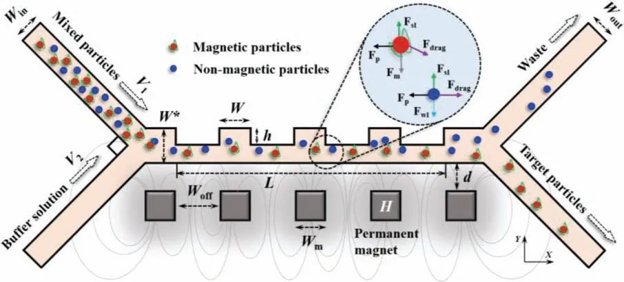
Fig.1.Schematic diagram of geometry-induced hydrodynamic and magnetic field synergistic magnetophoretic separation.Fdrag denotes drag force,Fm denotes magnetic force,and Fwl denotes wall lift force.The dashed line indicates that the wall lift force only works when the particles are in contact with the wall.Fp is pressure gradient force.Fsl is saffman lift force.The Magnetization intensity of the micropole is H.The microchannel,magnet and particles are not drawn to scale.
The local force balance of the two particles is shown in the detailed diagram.The operation claims effective separation only when the magnetic particle trajectory falls within the magnetophoretic width threshold [32].The density of magnetic particles is defined as 2200 kg/m3with the particle size is 4 μm,and the relative magnetic permeability of the particles is 2000.The density of non-magnetic particles is 1050 kg/m3with the particle size is 2 μm,and the relative magnetic permeability of the particles is 1.Separation efficiencyΨis defined as the ratio of the number of magnetic particlesPoexiting the target particle outlet to the total magnetic particlesPtot:
As attention is focused on sparse flow,which is achieved in practical applications by a dilution step,the carrier phase affects the particle motion mainly by drag force,without enough inertia of the particles to significantly perturb the fluid.Therefore,other forces with second-order effects,e.g.,interparticle forces,particleto-fluid forces,are allowed to be ignored as their contribution to the present study is much less than the burdens [33].In addition,the magnetic field strength is sufficiently small that the temperature change caused by the magnetic field is neglected and the thermophoretic force is not taken into account in the controlling equation of particle motion.Considering such a system modeling,it is effective to first solve for the flow and magnetic fields and then calculate the trajectories of the discrete particles.The numerical implementation can be found in the supplementary data.Grid convergence analysis and model validation show that the present numerical model is a quantitative fit to the experiment,as shown in Figs.S1-S3 (Supporting information).
The background magnetic field and the geometric-induced flow field characteristics are visually characterized,as shown in Fig.S4a (Supporting information).The flow velocity is affected by the fluid dynamics induced by the geometric features of the contraction and expansion.Considering only the flow effect,the particles will be moved near the microstructure side due to the laminar flow regime,which is influenced by the fluid drag forceFdragand the flow focusing effect of the sheath flow.When the centerline of the micropole coincides with that of the expansion region,the magnetic induction intensity is significantly focused and enhanced in the expansion region,and it is attenuated in the constriction region,as shown in the inset of Fig.S4b (Supporting information),which is called the orthogonal synergy effect.The velocity is minimized while the magnetic induction intensity is in the highest state.It can be expected that the flow velocity of magnetic particles decreases in the expansion region,while the magnetic field force is significant leading to a deflection of the motion path.The magnetic particles are accelerated by the traction force when they pass through the contracting region,where the magnetic field is relatively weak and only a small path deflection occurs.Non-magnetic particles still follow the flow field because they are not subject to magnetic field forces.
The trajectory of the particles subjected to the synergistic effect of the magnetic field and the geometry-induced flow field is depicted as shown in Fig.S5a (Supporting information),an oscillatory deflection along the Y-direction occurs under the constraint of the contraction geometry and magnetic field force.Oscillatory flow characteristics extend the coupling time over a limited separation length while reducing sensitivity to inappropriate operating parameters.The non-magnetic particle exhibits oscillatory acceleration dynamics,as shown in Fig.S5b (Supporting information),which implicates that the separation of impurity particles can be accelerated by increasing the main channel length.On the other hand,it is expected that the velocity of magnetic particles has no significant fluctuations with the synergistic effect of geometryinduced hydrodynamics and magnetic field,which allows to the robust operation of the system.The fluctuations of the magnetophoretic force shows a similar trend to the distribution of the magnetic flux density (Fig.S4b),with the particles suffering the greatest magnetophoretic force at the outer edge of the micropolar array and decreasing rapidly after separation.
Rectangular microstructures provide geometric constraints inducing specific hydrodynamics.First,the width factorW=40 μm is fixed and the trajectory of the magnetic particles is shown in Fig.2a whenh=15,20,25 and 27 μm.All snapshots are captured after 20 s of stable system operation.With the increase of depth factorh,the number of magnetic particles flowing out through the target particle collection outlet increases and the separation efficiency improves.The combination of the depth factor,which provides a geometric constraint on particle excursions in the Y-direction,and the geometry-induced hydrodynamics,which lengthens the particle’s travel distance and brings the particle closer to the strong magnetic field,enables particles with a wider distribution to obtain additional deflection capability.The magnetophoretic distribution width factorκis proposed to characterize the distribution width of magnetic particles in the outlet channel.κis defined as the ratio of the distribution range of magnetic particles parallel to the outlet channel cross-sectionWcto the outlet channel widthWout:
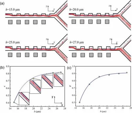
Fig.2.(a) The instantaneous trajectory of magnetic particles after stable operation of the system for 20 s when h=15,20,25,and 27 μm.The red one indicates magnetic particles,and the blue one indicates non-magnetic particles.Effect of h on (b) magnetophoretic distribution width and (c) separation efficiency when W=20 μm,d=30 μm,and Woff=50 μm.The inset shows the distribution of the magnetic particle motion path at the outlet.
As shown in Fig.2b,the magnetophoresis distribution width increases with increasinghand gradually tends to a constant value.Despite the fact that the increasinghwill lead to more efficient particle separation,the particles will be captured by the wall beyond a specific threshold.The trapped particles will accumulate on the wall under the magnetic field,which in turn decreases the magnetic particle separation efficiency [34].This conclusion can also be obtained from the inset of Fig.2b.Fig.2c demonstrates the variation of magnetic particle separation efficiency withh.It is clear that the separation efficiencyΨincreases from 50.2% to 91.7%with the increase ofhin the range of parameters studied.However,the contribution ofhto separation efficiency will no longer be significant whenh>25 μm,since a highhin practical applications leads to a narrow main channel width,which is prone to damage by aggregation and extrusion of particles or cells.
Next,the depth factorh=20 μm is fixed and the trajectory of the magnetic particles is shown in Fig.3a whenW=30,40,50,and 60 μm.The number of particles exiting the target outlet decreases over the parameter range of width factorWfrom 30 μm to 60 μm.The geometry-induced hydrodynamics dominates the trajectory of the particles under the condition of largeWcompared to the magnetic field force,resulting in larger Y-directional excursions and longer particle motion distances.However,it is clear that the particle excursion is less sensitive toWcompared toh.Therefore,the hydrodynamics induced by the width factor is convenient to implement coupling with the magnetic field to separate the magnetic particles precisely.The magnetophoretic distribution width tends to decrease linearly with increasing width factorWwith low sensitivity.In the range of available parameters,Wincreases by 50%,whileκdecreases by only 13%.Unexpectedly,the effect ofWon the magnetophoretic distribution range demonstrates a different behavior from that ofh.The magnetophoretic distribution width tends to exhibit uniform boundary shrinkage with the exception ofW=50 μm when an increase inW,which is attributed to the numerical error.Simultaneously,we find that whenWreaches the threshold value,the separation efficiency remains approximately 85%,and the separation efficiency decreases sharply by 3% asWincreases from 30 μm to 40 μm.Nevertheless,it does not mean that the lower theW,the higher the separation efficiency.Because our study shows that the particles are strongly attached to the wall by the magnetic field whenWis reduced to 0 (i.e.,no microstructure and the width of the main flow channel is reduced to half of the present).
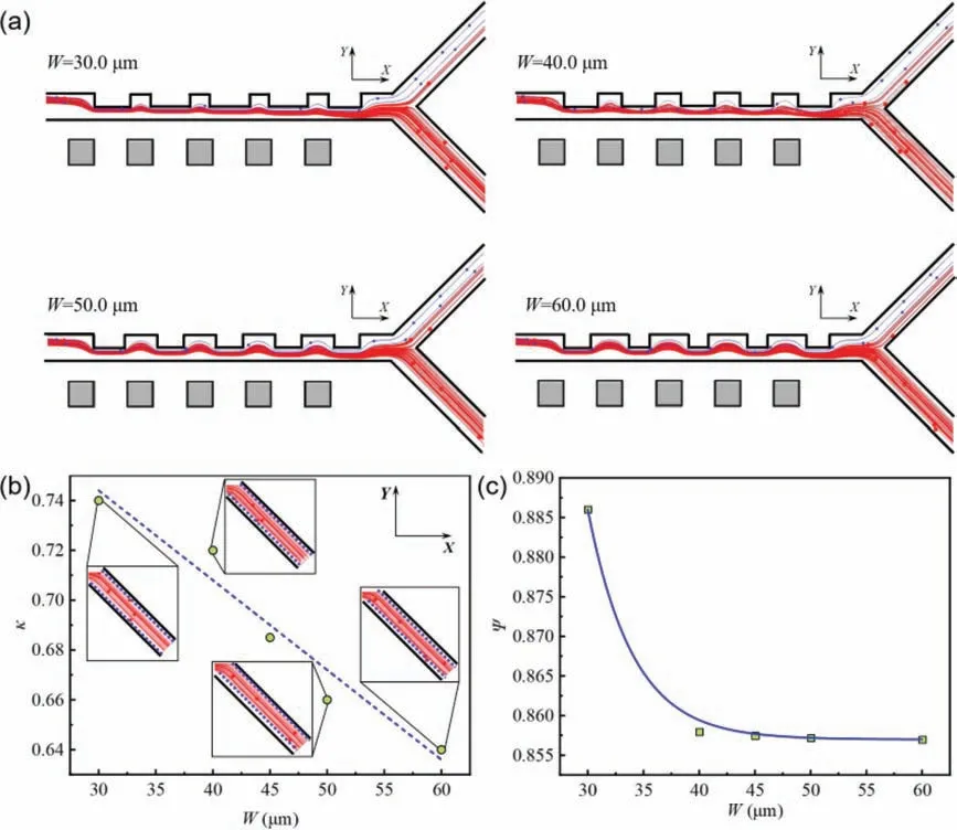
Fig.3.(a) The instantaneous trajectory of magnetic particles after stable operation of the system for 20 s when W=30,40,50,and 60 μm.The red one indicates magnetic particles,and the blue one indicates non-magnetic particles.Effect of W on (b) magnetophoretic distribution width and (c) separation efficiency when h=20 μm,d=30 μm,and Woff=50 μm.The inset shows the distribution of the magnetic particle motion path at the outlet.
In contrast to the orthogonal synergy,the offset synergy refers to the fact that the micropolar centerline is staggered by a specific offset distanceWofffrom the expansion region,rather than coinciding with the centerline of the expansion region.Here,we fix the depth factorhand the width factorWto investigate the effect of offset distanceWoffand the distance of permanent magnets from the main channeldon the particle separation efficiency.Fig.4 shows the variation curves of magnetophoretic distribution width factorκand particle separation efficiencyΨwith offset distance for variousd.We obtained similar conclusions as forhandW,where the magnetophoresis distribution width is in good agreement with the separation efficiency of magnetic particles.Over a certain range,both the magnetophoretic distribution width factorκand the magnetic particle separation efficiencyΨincrease with the increase of the offset distance.Instead,the separation efficiency decreases once a specific critical value is reached.Moreover,the critical value ofWoffincreases with the increase ofdfrom 29 μm to 31 μm.The decrease in the width of the magnetophoretic distribution in the studied parameter range was attributed to two factors.On the one hand,the offset distance is too large and the strong superimposed magnetic field acts on the contraction channel region.The high flow velocity of particles in the constriction channel with a short offset time fails to reach within the capture range of the collection channel.On the other hand,it is trapped on the wall by the magnetic field,which leads to a further reduction in the number of magnetic particles being separated.It is a consensus that the farther the permanent magnet is from the main channel,the smaller the offset distance of magnetic particles in the flow channel.Unexpectedly the offset synergistic effect of permanent magnet layout and geometry-induced hydrodynamics will instead overturn the conventional perception.It is possible to assume that there is an equilibrium value betweenWoffanddthat determines both the separation efficiency of the particles and the robust operation of the system.As shown in Fig.4b,the intersection of the three curves is the so-called equilibrium point,and the area filled by its conjunction has been filled with the base color to indicate the interval of stable system operation.
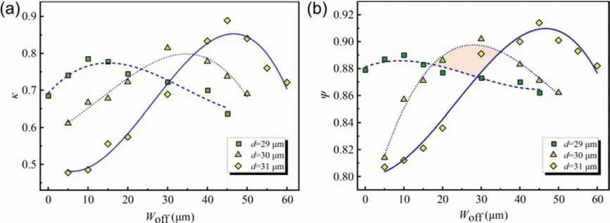
Fig.4.Effect of Woff on (a) magnetophoretic distribution width and (b) separation efficiency when d=29,30,31 μm,W=40 μm and h=20 μm.The area filled by the base color shows the range of parameters for the stable operation of the system.
Finally,the present model of magnetophoretic separation of particles is further generalized by dimensionless characterization of the system’s characteristic parameters.In this study,it is reasonable that the wall-induced lift is selectively ignored because the magnetic particles are separated before the range of allowable execution is reached.Besides,the virtual mass force only plays a significant role when the particle has a large acceleration,which is also neglected for the convenience of generalization.Therefore,the dominant forces acting on the particles include the drag forceFdrag,the Saffman lift forceFsland the magnetic field forceFm.With derivation and reasonable simplification,the velocity of the particle is expressed as:
whereλ=μπ+krpkdenotes the velocity gradient in the microfluidic channel.χdenotes magnetic susceptibility andχ=μr-1.
The magnetic field generated by a permanent magnet is scaled asH≈(d-y)2.When the distancedbetween the permanent magnet and the main channel is much larger than the width of the main channel with microstructure,dH2/dycan be expressed as
Then,the offset timetoffaffected by the strong magnetic field can be approximated astoff=n·wherendenotes the number of permanent magnet,anddenotes average speed of magnetic particles,which is due to the properties induced by the geometric effects (as shown in the inset of Fig.S4b).Finally,the offset distance of the particle can be dimensionless as:
where ˜h=h/W*,εdenotes a dimensionless scaling constant.Scottetal.[35] show the detailed calculation procedure of the dimensionless scaling parameters.Similarly,εcan be given by the following equation:
whereη==Woff/L.The lower wall surface of the main channel entrance is defined as the coordinate origin andn=5 in this study.The simulation result of the magnetic particle offset position is compared with the dimensionless model in good agreement as shown in Fig.5 whenh=20 μm.
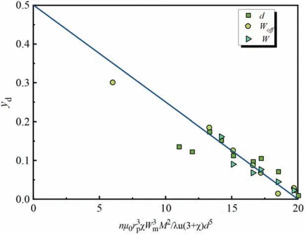
Fig.5.Dimensionless position yd plotted versus dimensionless design parameters.The theoretical model is plotted with a solid line and ε ≈0.025.
In this study,a novel particle separation LOC prototype integrated with microstructures and micropolar arrays is designed and characterized.By designing the correspondence between microstructure and micropoles,the synergistic effect of magnetic field and geometry-induced hydrodynamics is cleverly achieved.The effect of geometry and magnetic field layout on particle deflection is systematically analyzed.With other factors constant,Ψincreases from 50.2% to 91.7% with increasinghand decreases from 88.6%to 85.7% with increasingWover the studied parameter range.Besides,Ψincreases when in the range of 10-60 μm forWoffand then decreases beyond a specific critical value.Unexpectedly,we found that in the range ofWoffparameters studied,dincreasing from 29 μm to 31 μm leads to an increase in particle separation efficiency instead,which is counterintuitive.It means that it is allowed to adjust the layout of the permanent magnets coupled with geometry-induced hydrodynamics to optimize the separation performance of the system.Furthermore,the dimensionlessness of the system allows the prediction of the offset distance of magnetic particles at arbitrary scales,with further expansion of the applicability of the system.It is foreseen that the synergistic effect of geometryinduced hydrodynamics and magnetic field provides a novel and robust approach that will be an attractive addition to microfluidic magnetic particle sorting methods.
Declaration of competing interest
The authors declare that they have no known competing financial interests or personal relationships that could have appeared to influence the work reported in this paper.
Acknowledgments
This work was supported by the National Natural Science Foundation of China (Nos.11502044,U1906233),the Fundamental Research Funds for the Central Universities (No.DUT22JC08),the Liaoning Province’s Xing Liao Talents Program (No.XLYC2002108)and the Dalian City Supports Innovation and Entrepreneurship Projects for High-level Talents (No.2021RD16).
Supplementary materials
Supplementary material associated with this article can be found,in the online version,at doi:10.1016/j.cclet.2023.108646.
 Chinese Chemical Letters2024年2期
- Chinese Chemical Letters的其它文章
- The 3rd Xihua Chemistry and Biomedicine Forum
- Professor Hualiang Jiang: A tribute to an esteemed visionary chemist and pharmacist
- Recent advances in visible light-mediated chemical transformations of enaminones
- Development of porphyrin-based fluorescent sensors and sensor arrays for saccharide recognition
- Recent advances of versatile reagents as controllable building blocks in organic synthesis
- Synthetic host-guest pairs as novel bioorthogonal tools for pre-targeting☆
