
Enhancing Green Ammonia Electrosynthesis Through Tuning Sn Vacancies in Sn-Based MXene/MAX Hybrids
2024-03-22 08:46XinyuDaiZhenYiDuYingSunPingChenXiaoguangDuanJunjunZhangHuiLiYangFuBaohuaJiaLeiZhangWenhuiFangJieshanQiuTianyiMa
Nano-Micro Letters 2024年5期
Xinyu Dai, Zhen-Yi Du, Ying Sun✉, Ping Chen, Xiaoguang Duan, Junjun Zhang, Hui Li, Yang Fu, Baohua Jia, Lei Zhang, Wenhui Fang, Jieshan Qiu✉, Tianyi Ma✉
ABSTRACT Renewable energy driven N2 electroreduction with air as nitrogen source holds great promise for realizing scalable green ammonia production.However, relevant out-lab research is still in its infancy.Herein, a novel Sn-based MXene/MAX hybrid with abundant Sn vacancies, Sn@Ti2CTX/Ti2SnC—V, was synthesized by controlled etching Sn@Ti2SnC MAX phase and demonstrated as an efficient electrocatalyst for electrocatalytic N2 reduction.Due to the synergistic effect of MXene/MAX heterostructure, the existence of Sn vacancies and the highly dispersed Sn active sites, the obtained Sn@Ti2CTX/Ti2SnC—V exhibits an optimal NH3 yield of 28.4 µg h-1 mgcat-1 with an excellent FE of 15.57% at - 0.4 V versus reversible hydrogen electrode in 0.1 M Na2SO4, as well as an ultra-long durability.Noticeably, this catalyst represents a satisfactory NH3 yield rate of 10.53 µg h-1 mg-1 in the home-made simulation device, where commercial electrochemical photovoltaic cell was employed as power source, air and ultrapure water as feed stock.The as-proposed strategy represents great potential toward ammonia production in terms of financial cost according to the systematic technical economic analysis.This work is of significance for large-scale green ammonia production.
KEYWORDS Green ammonia synthesis; N2 electroreduction; Renewable energy; Sn; MXene/MAX hybrid
1 Introduction
Ammonia (NH3), as an important inorganic chemical, is not only widely used in industrial manufacture such as fertilizer, plastics and refrigerants, but also in the field of energy storage and conversion, especially the hydrogen storage [1—3].Up to now, the industrial NH3production mainly relies on the Haber Bosch (H-B) process, which requires harsh reaction conditions (300—600 °C, 150—350 atm), simultaneously generates enormous energy consumption and CO2emission [4—7].Considering energy and environmental factors, it is necessary to explore a sustainable and green method for NH3synthesis [8, 9].
Electrocatalytic N2reduction (ENRR) can directly use N2and ultrapure water as raw materials to realize NH3production when powered by electricity, which has become the most promising substitute for the energy-intensive H-B process [10—13].However, the extremely low Faradic efficiency and NH3yield are still far away from the requirements of practical applications due to the high bond energy of N≡N and the drastic competitive hydrogen evolution reaction (HER) [14—17].The key to solve these problems is to design and fabricate electrocatalysts with high ENRR selectivity and activity but inert HER activity [18—20].
Among various metal-based electrocatalysts that have been widely used in ENRR, Sn-based materials exhibit great potentials for large-scale electrocatalytic NH3production [21—23].As a P-block carbon group metal, Sn exhibit relatively high ENRR activity and selectivity due to its partially occupied p orbitals, which can provide electrons to the unoccupied anti-bonding orbitals of N2for effectively activating N≡N triple bond [24].Significantly, the vacant p orbitals endows Sn with inert HER activity [24, 25].Meanwhile, the advantages of abundant reserves, environmental friendliness and low cost also make Sn suitable for practical use [26].However, its ENRR performance is seriously impeded by the inferior conductivity, agglomeration and the limited electron transfer rate.In light of this, highly dispersed Sn to substrates with good conductivity is a wisdom strategy to improve its ENRR performance.MXenes, as a kind of twodimensional transition metal carbide/nitride materials, are generally prepared by selectively etching “A” atomic layers from their parent MAX phases[27], which possess unique properties of being electrocatalysts or substrates, such as tunable components, high specific surface area and outstanding electrical conductivity [28, 29].When combined with MAX, the heterostructure hybrid will be featured with more abundant active sites, such as defects, vacancies, adjustable electronic structures/electrical conductivity, improved structural and chemical stability, which is favor for achieving high NH3yield and FE [4, 30, 31].
Inspired by the “Hydrogen Farm Project” strategy proposed by Li and coworkers, which opens an economical way for practical hydrogen production and significantly improved the utilization of renewable energy [32], we turn our attention from laboratory research to build a smallscale “NH3farm”.The ENRR possesses the merits of simple device, easy operation and low investment, thus suitable for building an economical “NH3farm” with adjustable scale when powered by solar panels [33].This strategy would be more promising if air could be used instead of high-purity N2, which further reducing the energy consumption and CO2emission.However, the presence of O2in the air puts higher demands on the stability and selectivity of the catalysts for achieving high ENRR performance.
Herein, we for the first time synthesized a MXene/MAX hybrid with highly dispersed Sn and Sn vacancies, denoted as Sn@Ti2CTX/Ti2SnC—V, by a simply controlled HF etching method.This hybrid demonstrates a high NH3yield rate of 28.4 µg h-1mgcat-1at - 0.4 V versus RHE with an FE of 15.57% in neutral electrolyte with the help of the synergistic effect of fully exposed Sn active centers, Sn vacancies, and MXene/MAX heterostructure.Then a demonstrator for out-lab green NH3production was constructed, of which a commercial photovoltaic panel was used for directly converting solar energy to electricity to drive the ENRR process, and pre-purified air was employed as N2source.Notably, the obtained maximum NH3production rate of 10.53 µg h-1mg-1obtained by the present demonstrator does imply its promising potential in establishing “NH3farm” for the next generation energy conversion and storage.The economic feasibility of the present catalytic system was further proved by technical economic analysis.
2 Experimental
2.1 Preparation of Sn@Ti2SnC MAX
Sn@Ti2SnC was successfully prepared by a pressure-free method [34, 35].Typically, 9.57 g Ti powder (99.8%, 300 mesh), 24.0 g Sn powder (99.5%, 200 mesh) and 2.40 g graphite powder (99.95%, 500 mesh) were mixed thoroughly by ball-milling technique.Then, the mixture was placed into graphite molds pre-sprayed with BN layer and sintered in Ar atmosphere at 1200 °C for 2 h.Finally, the product was washed with ultrapure water for three times and vacuum dried at 60 °C to obtain Sn@Ti2SnC MAX.
2.2 Preparation of Sn@Ti2CTX/Ti2SnC-V
Sn@Ti2CTX/Ti2SnC—V was prepared by the traditional HF etching method [36, 37].Typically, 0.5 g Sn@Ti2SnC MAX was dispersed in 120 mL 40% HF solution and etched for a certain time at 25 °C, during which the etching time varies from 1 to 3 h to adjust the morphology and components of the target product.The mixture was centrifuged and washed with ultrapure water for three times to remove residual HF, dried in a vacuum drying oven at 60 °C for 12 h to obtain the Sn@Ti2CTX/Ti2SnC—V.
2.3 Preparation of the Working Electrode
The prepared catalyst was dispersed in a mixture of 20 μL Nafion solution (5 wt%), 480 μL ethanol and 500 μL ultrapure water for 1 h to form a uniform ink.20 µL of catalyst ink droplets were then placed on a 1 × 1 cm2carbon cloth (CC) and vacuum dried for subsequent measurements.
3 Results and Discussion
3.1 Characterization
Figure 1a illustrates the preparation process of the as-prepared Sn@Ti2CTX/Ti2SnC—V electrocatalyst.As shown in Fig.1a, Sn@Ti2SnC MAX was synthesized through the pressure-free method by using Ti, Sn and graphite powder as raw materials.The structure of Ti2SnC is considered as Sn atomic layer inserted periodically between Ti6C octahedral layers, that is, in Ti2SnC, the adjacent Ti—C—Ti bond chain is connected by an Sn atom, forming a layered structure [38].The traditional HF etching method was employed to synthesize the Sn@Ti2CTX/Ti2SnC—V.During the etching process, partial Sn layers are removed from their parent phases Sn@Ti2SnC by controlling the etching time to form Sn@Ti2CTX/Ti2SnC—V, because the Ti—C covalent bonds in the Ti2SnC MAX are stronger than the Sn—Ti bonds [39].At the same time, part of Sn atoms are etched away to form vacancies, which can act as the active sites of ENRR.
The crystalline phase of Sn@Ti2SnC and Sn@Ti2CTX/Ti2SnC—V was investigated by the X-ray diffraction (XRD).As it is shown in Fig.1b, the XRD pattern of the as-synthesized Sn@Ti2SnC sample shows characteristic peaks at 2θof 12.72°, 25.89°, 32.63°, 33.27°, 35.03°, 38.28°, 39.45°, 46.95°, 52.13°, 58.29° and 70.80° corresponding to the (002), (004), (100), (101), (102), (103), (006), (105), (106), (110) and (109) crystal planes of Ti2SnC (JCPDS 29-1353), indicating the successful synthesis of Ti2SnC MAX phase [40, 41].The diffraction peak located at 44.9° originates from (211) plane of Sn metal (JCPDS 04-0673) [42].Besides, no typical peaks stem from TiC and the Ti-Sn compounds are found, indicating the present synthesis method can avoid the formation of by-products.After being etched with HF solution, the presence of Ti2CTXis verified by the emergence of three typical peaks at 36.80°, 41.91° and 60.75°.Notably, the intensity of the peaks at 2θof 38.28° and 39.45° is sharply increased, which demonstrates a better crystal structure after etching.The disappearance of the characteristic peak at 2θof 44.9° indicates that part of Sn metal are etched away or their particle size are too small to be detected after etching with HF [40].Compared with those of Sn@Ti2SnC, the (002) and (004) peaks of Sn@Ti2CTX/Ti2SnC—V exhibit slight shift toward small angle, indicating the layer spacing becomes larger after etching.This increased interlayer spacing is more conducive to the electrolyte infiltration during the whole ENRR process.
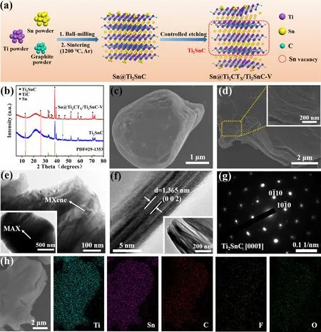
Fig.1 a Schematic diagram for the synthesis of Sn@Ti2CTX/Ti2SnC—V.b XRD patterns of Sn@Ti2SnC and Sn@Ti2CTX/Ti2SnC—V.c SEM image of Sn@Ti2SnC MAX.d SEM, e TEM, f HRTEM, g SAED pattern, h SEM and corresponding element (Ti, Sn, C, F and O) mapping images of Sn@Ti2CTX/Ti2SnC—V
The morphology and microstructure of the as-prepared Sn@Ti2SnC and Sn@Ti2CTX/Ti2SnC—V were examined by scanning electron microscopy (SEM) and transmission electron microscopy (TEM).As shown in Fig.1c, the original Sn@Ti2SnC MAX shows a plate-like structure [43].In addition, according to the mapping and energy-dispersive spectrometer (EDS) results of Sn@Ti2SnC (Fig.S1 and Table S1), the atomic ratio of Ti: Sn is 19.02: 10.03, which may attribute to the excess Sn decorated on the surface of the as-synthesized Ti2SnC.These Sn can act as active sites for enhancing the ENRR performance.Figure 1d illustrates the SEM image of the obtained Sn@Ti2CTX/Ti2SnC—V, which shows a two-dimensional (2D) layered structure with a larger layer spacing than that of Sn@Ti2SnC, attributing to the partially removing of the Sn layer by HF etching.TEM images of Sn@Ti2CTX/Ti2SnC—V further revealed that abundant cracks existed in 2D layered structures, as shown in Fig.1e, which helps to expose more active sites for a better electrocatalytic activity.From the HRTEM image of Sn@Ti2CTX/Ti2SnC—V (Fig.1f), the 1.365 nm crystal plane spacing is ascribed to the (002) plane of Sn@Ti2CTX/Ti2SnC—V, which has been broadened after HF etching [44].Figure 1g depicts the typical selection region electron diffraction (SAED) pattern of Sn@Ti2CTX/Ti2SnC—V, which is indexed as (0001) plane of Ti2SnC [45].In addition, the results of EDS (Fig.1h) verifies that the F and O terminations were uniformly dispersed throughout the Ti2CTX/Ti2SnC surface.
The surface chemical states of the two as-prepared samples were detected by X-ray photoelectron spectroscopy (XPS).As shown in Fig.2a, the survey scan spectrum of Sn@Ti2CTX/Ti2SnC—V shows Ti 2p, Sn 3d, C 1s, F 1sand O 1speaks, which are consistent with the results of the EDS (Fig.1h).The corresponding element quantification for Sn@Ti2SnC and Sn@Ti2CTX/Ti2SnC—V are shown in Fig.2b.As it is demonstrated that after etching with HF solution, the content of Sn drops from 6.17 to 2.05 at% as some of Sn atoms are removed from the Sn@Ti2SnC.The high-resolution Sn 3dXPS spectrum of Sn@Ti2SnC (Fig.2c, lower) displays four peaks at 495.0, 492.9, 486.6 and 484.5 eV, arising from the Sn(IV) 3d3/2, Sn(0) 3d3/2, Sn(IV) 3d5/2and Sn(0) 3d5/2, respectively.Meanwhile, as shown in the Sn 3dspectrum of Sn@Ti2CTX/Ti2SnC—V (Fig.2c, upper), the characteristic peaks of Sn(IV) 3d3/2, Sn(0) 3d3/2, Sn(IV) 3d5/2and Sn(0) 3d5/2are well presented at 495.0, 493, 486.6 and 484.6 eV.These typical Sn 3dpeaks of Sn@Ti2CTX/Ti2SnC—V exhibit ca.0.1 eV shift toward high binding energy comparing with those of Sn@Ti2SnC, indicating that the etching process generates the decrease of the electron density of the 3dorbital in Sn atoms, which is conducive to boosting the adsorption of N2[6].Besides, the characteristic peaks at 493.6 and 485.2 eV in the XPS spectrum of Sn@Ti2SnC/Ti2CTX-V are attributed to the Sn vacancy [46, 47].Defect engineering is a feasible strategy to improve the catalytic performance of ENRR by effectively adjusting the electronic and surface properties of catalysts [48—51].The A-layer metal Sn of MAX is etched during the etching process, thus forming Sn vacancies.The introduction of Sn vacancies can significantly tune the electronic structure of the catalyst and adjust the surface adsorption of the reaction intermediates, thus further improving the electrocatalytic activity [52, 53].Notably, these Sn vacancies are the active sites for chemisorption of N2, due to the accumulation of a large number of local electrons around them [6].At the same time, the empty p orbitals in Sn without occupied electrons are conducive to inhibiting HER.As shown in the highresolution Ti 2pXPS spectra of Sn@Ti2CTX/Ti2SnC—V (Fig.2d, upper), the fitting peaks located at 455.9 and 462.1 eV are assigned to the Ti 2ppeaks of Ti—C(II), while the peaks at 454.2/460.7 eV are corresponding to Ti—C(I) bond [54].The Ti 2ppeaks at bonding energy of 464.1 and 458.5 eV can be attributed to the Ti—O bond in the surface of Sn@Ti2CTX/Ti2SnC—V, which formed during the washing process [55].The peaks of Ti—C bond in the XPS spectra of Sn@Ti2CTX/Ti2SnC—V are negative shifted by 0.1 eV compared with those in the spectra of Sn@Ti2SnC (Fig.2d, lower), demonstrating the increase IN electron density of Ti 2pobtial.The high-resolution O 1sXPS spectrum of Sn@Ti2CTX/Ti2SnC—V (Fig.2e) displays three peaks at 529.96, 531.66 and 533.16 eV, arising from the Ti—O, Ti—O—H and C—O bonds, respectively [56].According to the reported experimental and theoretical studies, MXenes with O terminals exhibit superior stability due to the higher oxidation state of Ti bonding with O than F terminal [57].The high-resolution C 1sspectrum of Sn@Ti2CTX/Ti2SnC—V can be divided into four peaks at 281.76, 284.56, 285.56, and 288.66 eV, corresponding to Ti—C, C—C, C—O, and C=O, as depicted in Fig.2f [58].In addition, the existence of Sn vacancies was further confirmed by electron paramagnetic resonance (EPR) spectroscopy analysis (Fig.2g).According to the previous report [59, 60], the formation of Ti vacancies would present a paramagnetic center atg= 2.004—2.005.Nevertheless, this signature of Ti vacancies has not been observed in our samples.According to XPS and EPR analysis, the partially etched Sn@Ti2SnC with Sn vacancies were successfully prepared.Sn vacancies optimize the electronic structure of the Sn@Ti2CTX/Ti2SnC—V, thereby enhancing the charge transfer and reducing the adsorption energetics of the electrocatalytic reaction intermediates, thus improving the ENRR performance [61].
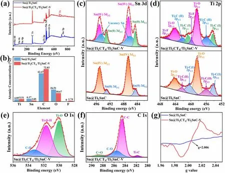
Fig.2 Surface chemical environments of Sn@Ti2CTX/Ti2SnC—V and Sn@Ti2SnC.a Survey scan spectra.b Atomic concentration.c Highresolution XPS spectra of Sn 3d, d Ti 2p, e O 1s and f C 1s.g EPR spectra
3.2 ENRR Performance
The ENRR performance of Sn@Ti2CTX/Ti2SnC—V sample were investigated in a gas-tight two-compartment H-cell with ultra-high purity N2saturated electrolyte.As shown in Fig.3a, the linear sweep voltammetry (LSV) curves of the catalyst in 0.1 M Na2SO4electrolyte saturated with Ar and N2exhibit similar shape.However, a higher current density is achieved in the N2-saturated electrolyte when the potential is more negative than - 0.2 V versus reversible hydrogen electrode (vs.RHE), implying that Sn@Ti2CTX/Ti2SnC—V/CC possesses catalytic activity for ENRR.Then, the ENRR performance of Sn@Ti2CTX/Ti2SnC—V was examined by Chronoamperometric (CA) measurements at different potentials for each 2 h (Fig.3b).Indophenol blue method was used to quantify the concentration of NH3in each electrolyte, corresponding calibration curves are shown in Figs.S2 and S3.The concentration of NH3in the electrolyte was determined by UV—Vis absorption spectra (Fig.S4), thus calculating the average yield of NH3and the corresponding FE.As shown in Fig.3c, an increase and subsequent decline in activity and selectivity for ENRR was observed as the potential became more negative.The Sn@Ti2CTX/Ti2SnC—V/CC demonstrates an optimal NH3yield of 28.4 µg h-1mg-1with an FE of 15.57% at - 0.4 V (vs.RHE).When potentials are more negative than - 0.4 V (vs.RHE), a notable decrease in NH3yield and FE is observed, suggesting that HER occupies the active sites and becomes dominant.For verifying the reliability of colorimetric method, the concentration of NH3was also determined by ammonia sensitive selective electrode method (Figs.S5 and S6).As depicted in Figs.3c and S7, within the allowable error range, the yields of NH3measured by this method is basically consistent with those determined by indophenol blue method, indicating that both methods are reliable for the quantitative analysis of NH3in the electrolytes.

Fig.3 a LSV curves of Sn@Ti2CTX/Ti2SnC—VC—V in Ar- and N2- saturated 0.1 M Na2SO4.b CA results of Sn@Ti2CTX/Ti2SnC—V obtained in N2- saturated 0.1 M Na2SO4 at different potentials.c NH3 yields and FEs at selected potentials.d NH3 yields and corresponding UV—Vis absorption spectra (inset) of electrolytes after electrolysis for 2 h under different control conditions.e NH3 yields and FEs of Sn@Ti2CTX/Ti2SnC—V obtained in the electrolyte saturated with N2 and Ar in alternating 2 h cycles at -0.4 V (vs.RHE), respectively.f UV—Vis absorption spectra of the electrolytes after 2 h ENRR testing at selected potentials determined by the Watt and Chrisp method.The inset shows the chromogenic reaction of the indicator with N2H4·H2O.g NH3 yields and FEs of Sn@Ti2CTX/Ti2SnC—V at - 0.4 V (vs.RHE) in various electrolytes.h NH3 yield and FE diagram of different Sn- and MXene-based ENRR catalysts [1—12].i NH3 yields and FEs of Sn@Ti2CTX/Ti2SnC—V, Sn@Ti2SnC and CC in N2- saturated 0.1 M Na2SO4 electrolyte at corresponding potentials
In addition, UV—Vis absorption spectra (the inset of Fig.3d) and corresponding NH3yields (Fig.3d) manifest no NH3is detected when electrocatalysis is performed over Sn@Ti2CTX/Ti2SnC—V in Ar-saturated electrolyte at 0.4 V (vs.RHE) or in N2-saturated electrolyte at open-circuit potential (OCP), demonstrating the detected NH3is neither from the electrolyte, nor from the impurities of N2gas, but from the electrocatalysis of N2over Sn@Ti2CTX/Ti2SnC—V.A 12-h alternate test in N2-and Ar-saturated 0.1 M Na2SO4at - 0.4 V (vs.RHE) was conducted with a 2-h interval (Fig.3e) to further investigate the N source of the generated NH3, which is consistent with the above results.Hydrazine (N2H4) is an important by-product of NRR process generated by the desorption of the *NH2NH2intermediates from the active sites without further hydrogenate, so it is essential to detect the concentration of N2H4in the electrolytes to evaluate the selectivity of catalyst [62].As shown in Figs.3f and S8, negligible N2H4is detected at potentials from - 0.3 to - 0.7 V (vs.RHE), indicating the excellent selectivity of Sn@Ti2CTX/Ti2SnC—V for the conversion of N2to NH3.
The ENRR performance of Sn@Ti2CTX/Ti2SnC—V in both acidic and alkaline electrolytes was studied under the same experimental conditions as that of in Na2SO4electrolyte.As shown in Figs.3g and S9—S12, Sn@Ti2CTX/Ti2SnC—V achieves an NH3yield of 15.22 µg h-1mg-1and maximum FE of 1.89% at - 0.4 V (vs.RHE) in 0.1 M HCl solution.This ultra-low FE is mainly due to the adequate proton source in acidic media, which promotes the HER side reaction, simultaneously comprise the selectivity toward ENRR to a large extent.In 0.1 M KHCO3electrolyte, Sn@Ti2CTX/Ti2SnC—V achieves an ordinary NH3yield of 5.22 µg h-1mg-1at - 0.4 V (vs.RHE) on account of the lack of proton sources in the alkaline medium, which seriously hinders the hydrogenation process of adsorbed N2on active sites.
Up to now, Sn- and MXene- based materials are intensively studied on ENRR as shown in Fig.3h and Table S9.Among these catalysts, Sn@Ti2CTX/Ti2SnC—V shows satisfactory performance on NH3yield and FE at lower potentials in the neutral electrolyte.For example, the FE of Sn@Ti2CTX/Ti2SnC—V is approximately 4.24 times of Sn dendrites (- 0.6 V) [63], 3.89 times of V2CTx(- 0.7 V) [64] and 1.35 times of SnO2—Ov(- 0.6 V) [65].At the same time, the NH3yield of Sn@Ti2CTX/Ti2SnC—V is higher than those of most MXenes, which is 1.4 times of Ti3C2TX(20.4 µg h-1mgcat-1) [66], 2.25 times of V2CTX(12.6 µg h-1mgcat-1) [64], and 2.72 times of Mo2CTX(10.43 µg h-1mgcat-1) [67].According to the above comparison, Sn@Ti2CTX/Ti2SnC—V is expected to be an excellent substrate and a composite catalyst for application in ENRR.
The ENRR performances of bare carbon cloth (CC), Sn@Ti2SnC/CC and Sn@Ti2CTX/Ti2SnC—V/CC were tested under the same conditions to evaluate the ENRR activity of different components and the ENRR mechanism of Sn@Ti2CTX/Ti2SnC—V.As demonstrated in Fig.3i, bare CC exhibits no ENRR activity at potentials arranging from - 0.3 to - 0.7 V (vs.RHE).The Sn@Ti2SnC MAX phase obtains its highest ammonia yield of 12.3 µg h-1mg-1at - 0.6 V (vs.RHE) which is only 43.9% of that of Sn@Ti2CTX/Ti2SnC—V (28.4 µg h-1mgcat-1) at the applied potential of - 0.4 V (vs.RHE).While its optimal FE (5.36%) at - 0.5 V (vs.RHE) is 34.4% of that obtained by Sn@Ti2CTX/Ti2SnC—V at - 0.4 V.Notably, Sn@Ti2CTX/Ti2SnC—V achieves an excellent NH3yield at low over-potential of - 0.4 V (vs.RHE), which is almost 4 times of Sn@Ti2SnC (6.97 µg h-1mg-1), highlighting the important role of Sn vacancies and Ti2CTXMXene for the improved ENRR activity.
The excellent ENRR performances of the as-prepared Sn@Ti2CTX/Ti2SnC—V are mainly attributed to the following aspects.Firstly, Ti2CTX/Ti2SnC hybrid as an ideal support with large specific surface area, enables Sn highly confined on the surface of Ti2CTX/Ti2SnC heterostructure without agglomeration, thus exposing more active sites.Importantly, the Ti2CTX/Ti2SnC heterostructure endows the 3d orbitals of Sn atoms with lower electron density, which helps to strengthen the Sn-N bond for a better adsorption of N2[6].This highly dispersed Sn and Sn vacancies, as active centers for the ENRR, boost the adsorption and activation of N2, simultaneously suppress the HER [23].For evaluating the electrochemically active surface area (ECSA), a series of cyclic voltammetry (CV, Fig.S13) measurements were performed to determine the double-layer capacitance (Cdl) [68].As shown in Fig.4a, the Cdlof Sn@Ti2CTX/Ti2SnC—V is 1.7 mF cm-2, significantly higher than that of Sn@Ti2SnC (0.13 mF cm-2), indicating that Sn@Ti2CTX/Ti2SnC—V provides more catalytic active sites for ENRR.The increased ECSA of Sn@Ti2CTX/Ti2SnC—V can be attributed to the widening of interlayer distance, and the Ti2CTX/Ti2SnC substrate for preventing the aggregation of Sn.Secondly, Sn@Ti2CTX/Ti2SnC—V exhibits excellent electrical conductivity and lower transmission resistance, which is conducive to accelerating the whole process of ENRR.Electrochemical impedance spectroscopy (EIS) was performed to evaluate the interfacial reaction and electrode kinetics during ENRR process (Fig.4b).The Sn@Ti2CTX/Ti2SnC—V exhibits a much smaller charge transfer resistance (Rct) of 21.6 Ω than that of Sn@Ti2SnC (24.8 Ω), which boosts the electron transportation from current collector to the active sites.This decrease in Rct is attributed to the increase in the MXene layer spacing [69] and the presence of the Ti2CTX/Ti2SnC heterostructure, in which the Ti2SnC phase can be effectively activated and the Ti2CTXphase acts as a good electron conductor, connecting the Sn active sites of Ti2SnC into the electrochemical network [70].Last but not least, according to the results of the contact angle test (Fig.4c), both of two samples loaded on the carbon cloth are hydrophobic, that can effectively prevent water molecules from contacting with active sites for inhibiting HER, thus further accelerating the ENRR process [13, 71].Overall, the factors mentioned above synergistically endow Sn@Ti2CTX/Ti2SnC—V with superior ENRR activity.
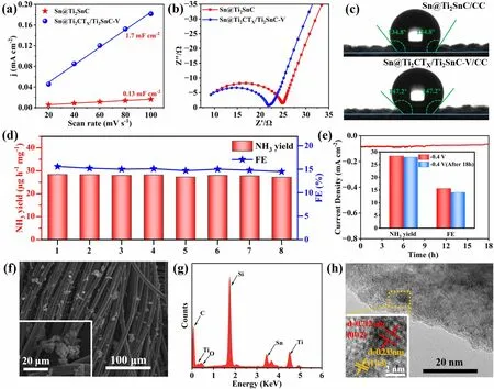
Fig.4 a Cdl, b EIS, and c water droplet contact angle measurement of Sn@Ti2SnC/CC and Sn@Ti2CTX/Ti2SnC—V/CC.d Cycling tests of Sn@Ti2CTX/Ti2SnC—V and corresponding NH3 yields and FEs after each cycle.e Chronoamperometry test of Sn@Ti2CTX/Ti2SnC—V/CC at - 0.4 V (vs.RHE) with the inset demonstrates FEs and NH3 yields before and after 18 h durability test.f SEM, g EDS, h TEM and corresponding HRTEM images (inset) of Sn@Ti2CTX/Ti2SnC—V/CC after 18 h electrocatalysis
Stability is of importance as indexes to evaluate the performance of electrocatalysts, especially for practical applications.For this reason, cycling tests and long-term continuous potentiostatic electrolysis were carried out to evaluate the stability of the as-synthesized Sn@Ti2CTX/Ti2SnC—V electrode.As shown in Fig.4d, no significant reduction in NH3yields and FEs is observed during eight parallel tests at - 0.4 V (vs.RHE) in 0.1 M Na2SO4for 2 h, indicating the high electrochemical stability of Sn@Ti2CTX/Ti2SnC—V toward ENRR in neutral media.In addition, the stable current density of 18 h long-term continuous potentiostatic electrolysis at - 0.4 V (vs.RHE) with 1.7% loss in NH3yield and 9.4% loss in FE further demonstrates the remarkable electrochemical durability of Sn@Ti2CTX/Ti2SnC—V (Fig.4e).Furthermore, the results of SEM (Fig.4f), EDS (Fig.4g) and TEM (Fig.4h) of Sn@Ti2CTX/Ti2SnC—V after the ENRR tests confirm that the morphology and structure of the catalyst are almost unchanged after long term electrocatalysis, proving its robustness toward ENRR.This excellent durability of Sn@Ti2CTX/Ti2SnC—V is attributed to the existence of partial etched Ti2SnC MAX phase and O functional groups on the surface of Ti2CTXMXene.The O terminals with strong electron absorption properties render Ti atoms in Ti2CTXMXene with the highest oxidation state, thus boost the antioxidant capacity of Ti2CTXMXene [57].
3.3 PV-EC System
Another crucial factor for ENRR realizing large-scale green NH3production is reducing the cost and energy consumption of this technique, which can realize by shortening the energy utilization path and avoiding using high-purity N2as nitrogen source.Among various green electricity generation techniques, “solar farm” realized by photovoltaics (PV) panels is regarded as the most promising one due to the abundant and clean energy source of sunlight, the mature photoelectric conversion device, and the universality of this technique around the world [72].In view of this, photovoltaic electrochemical (PV-EC) system represents an effective and sustainable way for green NH3production, due to the combination of direct utilization of solar energy and the merits of electrocatalysis [73].Therefore, we transfer our effort from laboratory experiments to outdoor investigations, which directly use solar panels as electricity source, air as nitrogen source, ultrapure water as proton source for the ENRR under environmental conditions.
Firstly, photosensitivity of Sn@Ti2CTX/Ti2SnC—V was tested to investigate the effect of sunlight illumination on the ENRR process.As shown in Figs.5a and S14, the photocurrent response of Sn@Ti2CTX/Ti2SnC—V measured at 0 V shows little difference on photocurrent between Xe light irradiation and dark, indicating the subtle influence of sunlight illumination on ENRR.In addition, as shown in the EIS (Fig.5b), the transmission resistance of Sn@Ti2CTX/Ti2SnC—V under Xe lamp irradiation is smaller than that without irradiation, indicating that sunlight illumination can reduce the resistance of Sn@Ti2CTX/Ti2SnC—V and promote the charge transfer during ENRR.Then, for determining the optimal potential for NH3production in the home-made electrocatalytic demonstrator outside the laboratory, we did comparison tests at potentials of 1.5, 1.6, 1.7 and 1.8 V, respectively, in a quartz H-type electrolytic cell filled with N2-saturated 0.1 M Na2SO4, of which Sn@Ti2CTX/Ti2SnC—V/CC was used as working electrode and a carbon rod as counter electrode.The Chronoamperometric measurements of Sn@Ti2CTX/Ti2SnC—V and the corresponding UV—Vis absorption spectra are shown in Figs.5c, d and S15—S17.The optimal NH3yield of 26.37 µg h-1mg-1obtained at 1.8 V (Fig.5e), which is chosen as the applied potential.Finally, ENRR experiments were performed outside the laboratory by using a commercially available photovoltaic (PV) solar panel (0.55 W, 110 mA, 5 V) and a dual electrode configuration filled with 0.1 M Na2SO4saturated with purified air (Figs.5f and S18).Corresponding UV—visible absorption spectral curve is shown in Fig.5g.Despite the presence of O2, this system achieved an optimal NH3yield of 10.53 µg h-1mg-1in 1.8 V.Although this NH3yield is only 40% of that obtained in ultra-high purity N2saturated electrolyte, it does provide a practical, economical and carbon neutral way for green NH3production.
In addition, a comparative techno-economic analysis of the PV-EC system was performed based on state-of-theart demonstration for further investigating the economics of PV driven NH3production, as depicted in Table S2.To achieve a reliable analysis, the annual solar radiation energy of Tibet, China (1875 kWh m-2) was used as the reference.Tables S3—S5 summarize the main assumptions for the economic analysis.In order to accommodate independent sustainable farms, it is assumed that the NH3yield of PV-EC module is 1000 kg/year.Based on the NH3yield obtained outside the laboratory (10.53 µg h-1mg-1), the calculated minimum selling price (MSP) of NH3is $7.18 kg-1.The cost details of NH3MSP are shown in Fig.5h and Table S6.PV module with its capital and operational costs accounting for 61% and 16% of the total cost act as the major cost driver.EC module with the capital and operational costs accounting for 17% and 6% of total cost is responsible for the second largest cost driver.Assuming that N2as the nitrogen source in two-electrode system is the ideal scenario, when the number of photovoltaic modules sharply reduces from 139 to 59, and the number of electrochemical components reduces from 4380 to 2040.Therefore, the MSP of NH3is greatly decreased to $3.04 kg-1(Fig.5h and Table S7).Assuming that the cost of PV modules is reduced to 50% of its original, the MSP of NH3further reduces to $1.87 kg-1(Fig.5h and Table S8).If take the by-product of H2into consideration, which will compensate for the cost, the MSP will achieve a lower price.These results demonstrate that the PV-EC module has a great prospect for industrialization ($0.5 kg-1) in terms of cost price.According to the global horizontal irradiation map (Fig.S19) and the photovoltaic development potential map with the red color shows the potential (Fig.S20), this PV-EC system has potential applications in more than half of the world’s land areas, and it also works in the ocean.The photovoltaic driven ENRR would be a cost-effective and sustainable strategy for effi-cient NH3production.
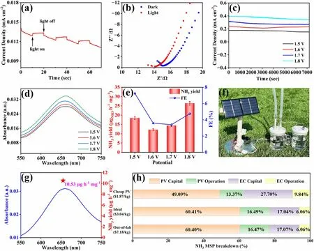
Fig.5 a Photocurrent response of Sn@Ti2CTX/Ti2SnC—V obtained on/off 150 W Xe light irradiation at the potential of 0 V in N2-saturated 0.1 M Na2SO4.b EIS of Sn@Ti2CTX/Ti2SnC—V in light and dark conditions.c Chronoamperometric measurements results under different potentials.d UV—Vis absorption spectra of the electrolytes after 2 h ENRR and corresponding e NH3 yields and FEs of Sn@Ti2CTX/Ti2SnC—V at different potentials in a two-electrode configuration.f Real picture of the PV-EC system.g UV—visible spectrum and NH3 yield (star location) after reaction for 2 h under the sun at 1.8 V.The techno-economic accounting and analysis.h A cost breakdown of the minimum selling price for renewable NH3
4 Conclusions
In summary, Sn@Ti2CTX/Ti2SnC heterostructure with abundant Sn vacancies was successfully prepared by controlled etching of Sn@Ti2SnC MAX phase.The highly dispersed Sn atoms throughout the Ti2CTX/Ti2SnC heterostructure provide adequate active sites for adsorption and activation of N2, simultaneously, the Sn vacancies between layers accelerate the charge transfer rate and reduce the adsorption energetics of the intermediates, thereby boosting the ENRR activity.Meanwhile, Ti2CTX/Ti2SnC heterostructure realize the balance of providing large active surface area and accelerating the stability.Therefore, Sn@Ti2CTX/Ti2SnC demonstrates a striking ENRR performance (NH3yield: 28.4 µg h-1mgcat-1, FE: 15.57%) at - 0.4 V versus RHE with an excellent durability up to 18 h in 0.1 M Na2SO4.In addition, a PV-EC modular demonstrator based on Sn@Ti2CTX/Ti2SnC—V electrode with a maximum ammonia productivity of 10.53 µg h-1mg-1in neutral electrolyte is proposed, which can successfully synthesize green ammonia from solar energy, ultrapure water and nitrogen form air.The systematic techno-economic analysis proves that this strategy is economic feasible and will open up a new direction for ammonia production beyond the laboratory in the future.
AcknowledgementsThis work was supported by the National Natural Science Foundation of China (Nos.22308139, 52071171, 52202248), Natural Science Foundation of Liaoning Province (2023-MS-140), Liaoning BaiQianWan Talents Program (LNBQW2018B0048), Shenyang Science and Technology Project (21-108-9-04), Young Scientific and Technological Talents Project of the Department of Education of Liaoning Province (LQN202008), Key Research Project of Department of Education of Liaoning Province (LJKZZ20220015), Foundation of State Key Laboratory of Clean and Efficient Coal Utilization, Taiyuan University of Technology (MJNYSKL202301), Foundation of State Key Laboratory of High-efficiency Utilization of Coal and Green Chemical Engineering (KF2023006), Anhui Province Key Laboratory of Coal Clean Conversion and High Valued Utilization, Anhui University of Technology (CHV22-05), Australian Research Council (ARC) through Future Fellowship (FT210100298, FT210100806), Discovery Project (DP220100603), Linkage Project (LP210100467, LP210200504, LP210200345, LP220100088), and Industrial Transformation Training Centre (IC180100005) schemes, and the Australian Government through the Cooperative Research Centres Projects (CRCPXIII000077).
Declarations
Conflict of InterestsThe authors declare no interest conflict.They have no known competing financial interest or personal relationships that could have appeared to influence the work reported in this paper.
Open AccessThis article is licensed under a Creative Commons Attribution 4.0 International License, which permits use, sharing, adaptation, distribution and reproduction in any medium or format, as long as you give appropriate credit to the original author(s) and the source, provide a link to the Creative Commons licence, and indicate if changes were made.The images or other third party material in this article are included in the article’s Creative Commons licence, unless indicated otherwise in a credit line to the material.If material is not included in the article’s Creative Commons licence and your intended use is not permitted by statutory regulation or exceeds the permitted use, you will need to obtain permission directly from the copyright holder.To view a copy of this licence, visit http:// creat iveco mmons.org/ licen ses/ by/4.0/.
Supplementary InformationThe online version contains supplementary material available at https:// doi.org/ 10.1007/ s40820- 023- 01303-2.

- Nano-Micro Letters的其它文章
- A Generic Strategy to Create Mechanically Interlocked Nanocomposite/Hydrogel Hybrid Electrodes for Epidermal Electronics
- Atomically Substitutional Engineering of Transition Metal Dichalcogenide Layers for Enhancing Tailored Properties and Superior Applications
- Chalcogenide Ovonic Threshold Switching Selector
- Highly Efficient Aligned Ion-Conducting Network and Interface Chemistries for Depolarized All-Solid-State Lithium Metal Batteries
- Integrating Levels of Hierarchical Organization in Porous Organic Molecular Materials
- Strain-Induced Surface Interface Dual Polarization Constructs PML-Cu/Bi12O17Br2 High-Density Active Sites for CO2 Photoreduction