Interaction Mechanisms between Natural Debris Flow and Rigid Barrier Deflectors:A New Perspective for Rational Design and Optimal Arrangement
Yu Huang,Beilei Liu,Dianlei Fengand Hao Shi
1Department of Geotechnical Engineering,College of Civil Engineering,Tongji University,Shanghai,200092,China
2Department of Hydraulic Engineering,College of Civil Engineering,Tongji University,Shanghai,200092,China
ABSTRACT Rigid barrier deflectors can effectively prevent overspilling landslides,and can satisfy disaster prevention requirements.However,the mechanisms of interaction between natural granular flow and rigid barrier deflectors require further investigation.To date,few studies have investigated the impact of deflectors on controlling viscous debris flows for geological disaster prevention.To investigate the effect of rigid barrier deflectors on impact mechanisms,a numerical model using the smoothed particle hydrodynamics(SPH)method with the Herschel–Bulkley model is proposed to simulate the interaction between natural viscous flow and single/dual barriers with and without deflectors.This model was validated using laboratory flume test data from the literature.Then, the model was used to investigate the influence of the deflector angle and multi-barrier arrangements.The optimal configuration of multi-barriers was analyzed with consideration to the barrier height and distance between the barriers,because these metrics have a significant impact on the viscous flow pile-up, run-up, and overflow mechanisms.The investigation considered the energy dissipation process,retention efficiency,and dead-zone formation.Compared with bare barriers with similar geometric characteristics and spatial distribution, rigid barriers with deflectors exhibit superior effectiveness in preventing the overflow and overspilling of viscous debris flow.Recommendations for the rational design of deflectors and the optimal arrangement of multi-barriers are provided to mitigate geological disasters.
KEYWORDS Rigid barrier deflectors; deflector angle; single-barrier; dual-barrier arrangements; viscous debris flow;over-spilling;delta-plus-SPH
1 Introduction
Rigid barriers can effectively prevent natural hazards caused by mass-wasting debris flows in mountainous regions[1,2].In large-scale natural debris flow disasters,bare barriers cannot retain flow material,and do not satisfy existing disaster protection requirements.Many design recommendations have been proposed to prevent debris flows from overflowing and overspilling [3,4].For mitigation purposes,deflectors positioned atop the wall stem can redirect debris flows.The parapets in coastal structures are prototypes of these deflectors,and were initially designed to minimize water overspill and splash back[5,6].The reduction factor quantifies the effectiveness of deflectors by measuring the discharge that overtops a barrier with a deflector in place and dividing this amount by the discharge that overtops a barrier without a deflector[7].The comparison of bare barriers and rigid barriers with deflectors is shown in detail in Fig.1,whereBheightis the barrier height,Lis the horizontal length of deflectors,andhmaxis the maximum approach debris thickness.Owing to the larger volume of natural debris material,it is necessary to consider the barrier height,deflector height,and angles(equal to the horizontal length L)of the deflectors at the wall crest[8].Because the rheological behaviors of water and debris flow are different,the design of deflectors,which aim to prevent natural debris flow,should be optimized based on parapets.
The interactions between debris flows and deflectors have been investigated using both physical and numerical models.Choi et al.[12]conducted preliminary small-scale flume experiments to investigate dry granular flow interaction with deflectors that had different angles.Ng et al.[4]conducted flume tests to investigate the flow kinematics of dry sand flows and the energy dissipation under the influence of deflectors.The results obtained by previous studies have revealed that conditions for adverse overflow strongly depend on the effective barrier height and length,and deflector angle.Notably, the flow characteristics of viscous debris flow differ significantly to those of dry granular flow,resulting in overspilling and hydrodynamic dead-zone formation[13–15].Ng et al.[16]discussed the impact kinematics of fluids, including water and slurry, under different deflector geometries.A modified impact equation considering the flow-deflector interactions has been proposed.The impact,run-up,and pile-up mechanisms of saturated debris flow exhibit significant differences compared with those of dry granular flows in flow–barrier interactions.Consequently, research on the influence of deflectors on natural debris flow remains limited.Moreover, an appropriate constitutive model is required to capture the dynamic behavior of natural debris flow accurately and elucidate the flow–deflector interaction mechanisms.
Natural debris flow, which is a typical non-Newtonian fluid, has the characteristics of shear thinning or shear thickening behavior [17].Various non-Newtonian rheological models, such as the Bingham model [18,19], power-law model [20], and Herschel–Bulkley model [21,22], have been proposed.Moreover,the constant threshold of yield stress(τy)and the value of the power-law exponent(N)are key factors for changing the model in certain situations[23].The Herschel–Bulkley fluid model has been widely used to calculate the dynamic viscosity in debris flow modeling when the power-law exponentN/=1 and yield stressτy/=0.This study implemented the Herschel–Bulkley(HB)model to simulate the complex rheological behavior of debris flow and elucidate the influence of defectors on controlling viscous debris flow.
The grid-based method and particle-based method are often used for modeling flow–structure interactions.For large-deformation debris flows, mesh-free methods can avoid the grid distortion in grid-based methods.Methods such as the discrete element method (DEM) [24], coupled computational fluid dynamics and discrete element method (CFD-DEM) [25], material point method(MPM)[26],and smoothed particle hydrodynamics(SPH)[27]are typical particle-based methods for capturing the complicated flow–barrier interactions of classic geomechanical problems.Among them,the SPH method has many advantages in solving large deformation problems over traditional gridbased methods[24–26].This method has become widespread owing to its accuracy and stability under complex boundary conditions for the quantitative analysis of the mechanisms of dynamic interaction between natural debris flows and rigid barriers[27–29].Wang et al.[30]investigated the flow behavior of debris flows using SPH, focusing on the propagation analysis of debris flows in terms of runout distance and flow velocity.Dai et al.[31]used SPH to investigate the interaction between debris flows and structures,and estimated the impact force.Sun et al.[32,33]proposed the particle shifting technique(PST)to maintain the numerical stability and accuracy of theδ-plus-SPH scheme.Notably,theδ-SPH scheme introduces an artificial diffusive term to improve the high-frequency noise in the pressure field.Relevant results have revealed thatδ-plus-SPH is feasible and reliable for investigating the dynamic interaction between debris flows and structures.
This study developed aδ-plus-SPH method and used it to investigate the influence of deflectors on the dynamic behavior of viscous debris flow.The primary objective of this study was to investigate the influence of deflector angles on viscous debris flow in both single-barrier and dual-barrier systems.The presentation and validation of the numerical results are obtained by using theδ-plus-SPH model,followed by the discussion of energy dissipation process,retention efficiency,and run-up and overflow mechanisms of viscous debris flow in rigid barriers with and without deflectors.
2 Numerical Modeling
2.1 Numerical Method
In the domain of computational fluid dynamics, the SPH method has emerged as a prominent mesh-free Lagrangian approach[28].Central to the SPH method is the utilization of kernel functions to compute particle interactions, ensuring both consistency and stability in the numerical representation.This subsection presents the fundamental principles and mathematical formulations of the SPH method.Each equation is systematically introduced,accompanied by a rigorous exposition of its derivation,underlying assumptions,and its role within the overarching SPH framework.The governing equations(Eq.(1))include the mass and momentum balance,and require numerical solutions.
Eq.(1) has the derivative form of density and velocity;trepresents time,ρdenotes the density,andudenotes the velocity.Therefore,is the time derivative of density andis the time derivative of velocity.In the momentum equation,Prepresents pressure;τandgdenote the deviatoric shear stress tensor and body force,respectively.In this study,the equation of state was used to calculate the pressure field.In Eq.(2),Csis the numerical sound speed,ρ0represents the reference density,andP0denotes the background pressure.
Recently, the SPH method has been widely used to simulate large-deformation natural debris flows,because it can capture free surfaces and large deformable geomaterial boundaries[34].By using the SPH method,the governing equations can be efficiently solved.The physical properties carried by the arbitrarily distributed discrete particles of debris flow are based on the distributed particles within a smoothing length.The field functionf (ri)and its derivative can be approximated as follows:
where<>denotes the SPH approximation.
In this study,the particle shifting technique(PST)andδ-SPH were used to maintain the uniformity of particles and improve the pressure oscillations[37,38].The discrete form of Eq.(1)can be expressed as follows(⊗is the Kronecker product):
In two-dimensional problems,the coefficient of the viscous termα=8[39],and it is recommended that the diffusion coefficientδis set to 0.1.The diffusion termDiis introduced in Eq.(7)to remove the pressure noise[40].
where ∇(ρ)L
iis the density gradient in Eq.(7), which is computed using the renormalized gradient form and expressed as follows:
The PST method is used to avoid arbitrary particle configuration,and the shifting velocityis calculated[32]as follows:
In Eq.(9),umaxrepresents the maximum velocity;Δxirefers to the initial particle distance;Randnare equal to 0.2 and 4,respectively[39].The velocity deviationδuiis calculated to avoid large inconsistent kinematic boundary conditions[41].
In Eq.(11),λidenotes the minimum eigenvalue of the tensor;nirefers to the vector perpendicular to the free surface of particlei[26].
This study employed the generalized wall boundary method and 4th-order Runge–Kutta timeintegration technique to model intricate geometries.Notably,dummy particles can be used to model the interactions between the fluid phase and a solid boundary[42].
2.2 Numerical Model Setup and Rheological Model
Because deflectors are an efficient debris flow deflection method,a previous study[12]conducted flume tests to investigate the influence of different rigid barrier deflector angles.The overflow mechanisms are characterized by viscous flow launching off ramp-like dead zones, launch lengthD, launch velocityvo, and other parameters, providing practicable measures for better retaining the viscous flow material volume.Therefore, many studies have proposed a dual-barrier system to investigate the upstream overflow behavior and downstream run-up impact mechanisms using physical modeling and numerical simulations[26,43,44].In this study,2D numerical flume tests were conducted using a SPH model to investigate the overflow behavior and impact mechanisms of a dual-barrier system with deflectors.
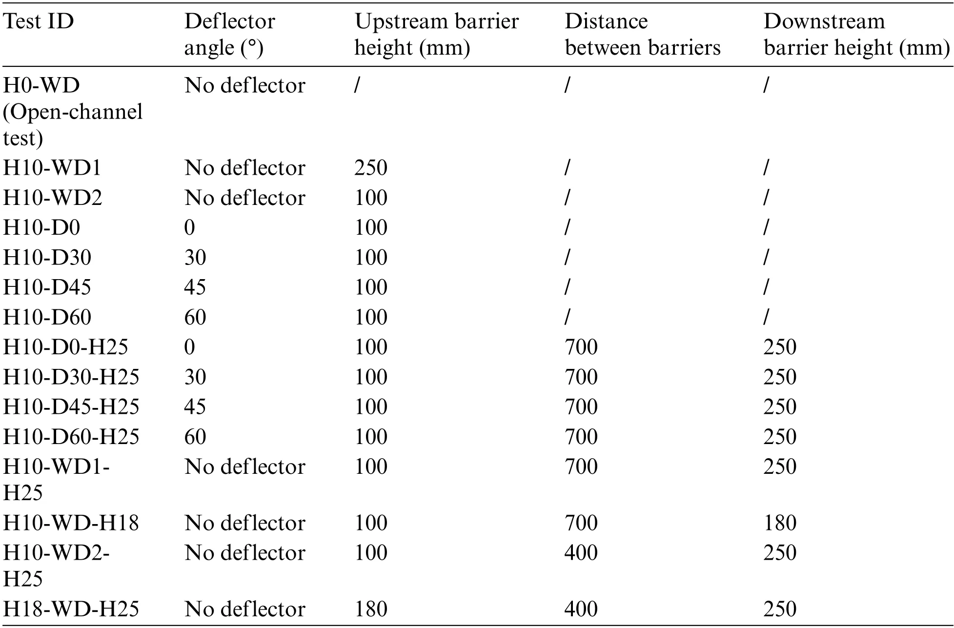
The setup of the 3D numerical flume models of the single barrier with deflectors and dualbarrier system are illustrated in Figs.2a and 2b, and the detailed geometry of the 2D dual-barrier system with deflectors is shown in Fig.2c.A rigid barrier with a 65-mm-long deflector (Ld) was placed 800 mm from the initial position of the viscous granular flow,and the height of the upstream barrier(Bu)was 100 mm.The downstream barrier(Bd)was sufficiently tall to intercept overflowing debris flow.The distance between the barriers (Dud) is described in [43].Initially, the viscous debris flow volume was set up (cross-section: 300 mm × 200 mm).The slope angleαwas fixed to 26°.Various deflector angles were considered,based on the flume test described in a previous study[12].More detailed information regarding the modeling scenarios,including various barrier heights and the distance between barriers are listed in Table 3.This study adopted a unit weight of 11.35 kN·m-3for natural debris flow containing fine-grained pyroclastic soil in southern Italy,as estimated fromin-situexperimental data [18].Natural debris flows are a mixture of solid particles and viscous liquid [45].High-density features always appear in high-mobility and large debris flow events[46].In this study,the debris flow was modeled as a homogeneous non-Newtonian fluid using the Herschel–Bulkley model.
The Herschel–Bulkley (HB) model was used to model the debris flow.The HB model has been widely used to investigate the rheological behavior of natural debris flow[47,48].The deviatoric viscous stress tensorτis expressed as follows:
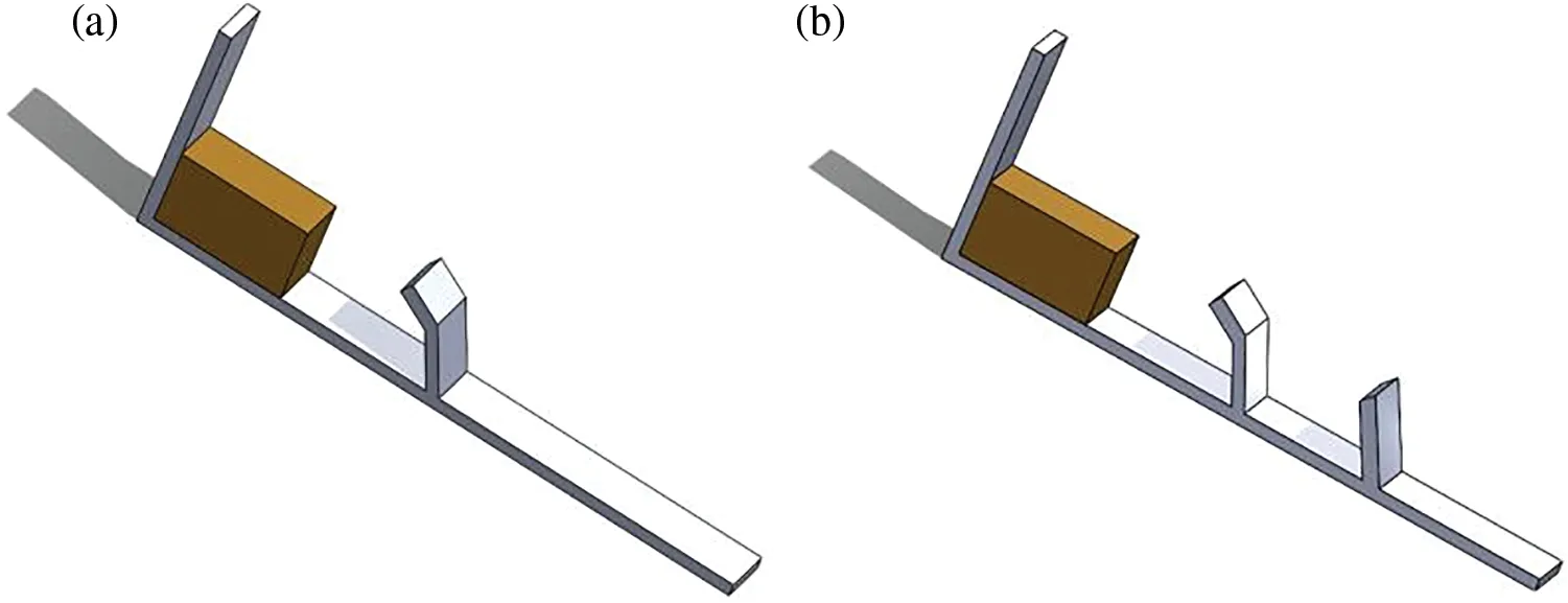
Figure 2: (Continued)
In Eq.(12),τy=ptanϕ+cis the yield stress used for landslide modeling [31];ϕandcare the frictional angle and cohesion,respectively.For viscous debris flow,τyis a modeling constant,Kis the consistency index,andNis the power-law exponent.The rheological parameters used in the numerical modeling were obtained from experiments[18]and are listed in Table 1.Additionally,is the second invariant of the rate-of-strain tensor;Sis the rate-of-strain tensor calculated by the velocity gradient∇ubetween particles,as follows:
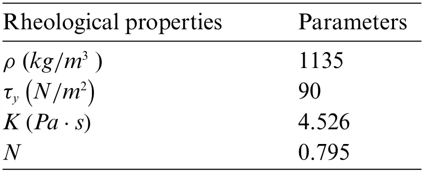
Table 1: Rheological parameters used in numerical modeling
The apparent viscosityηappcan be used to calculate the stress tensorτ, which is expressed as follows:
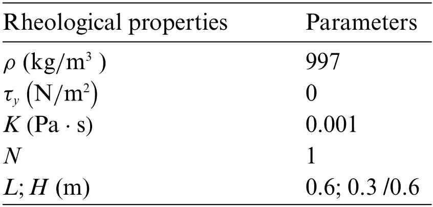
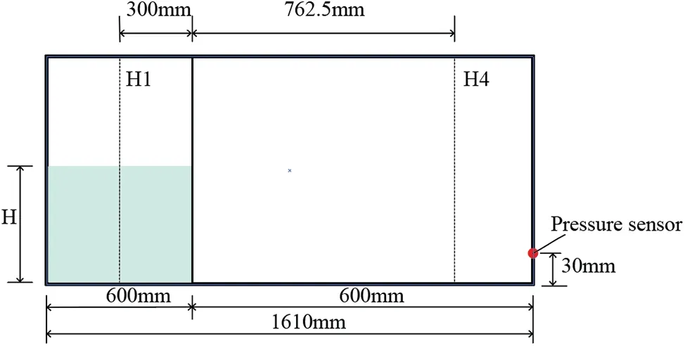
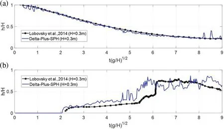
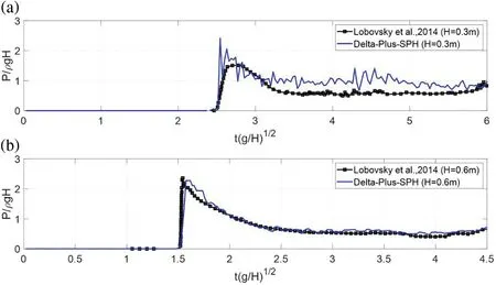
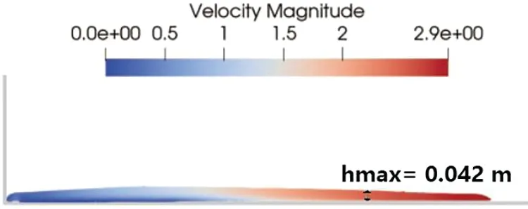
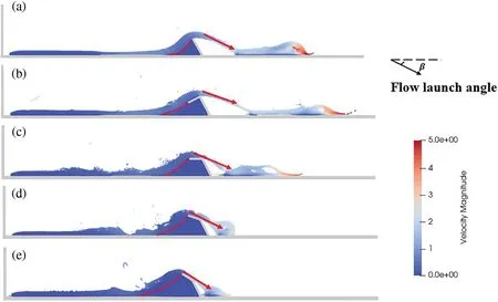
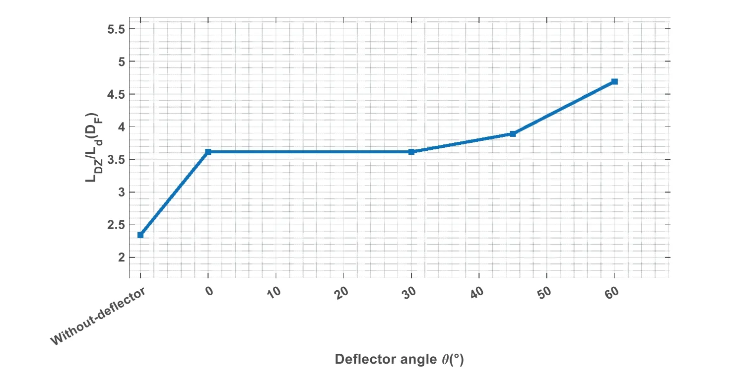
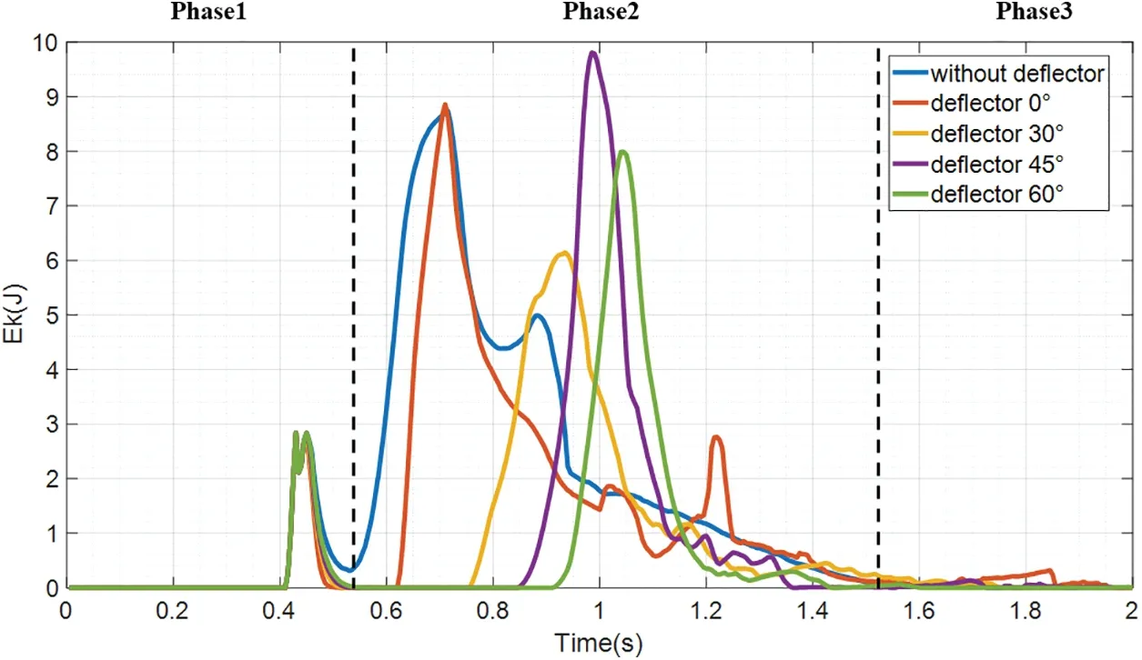
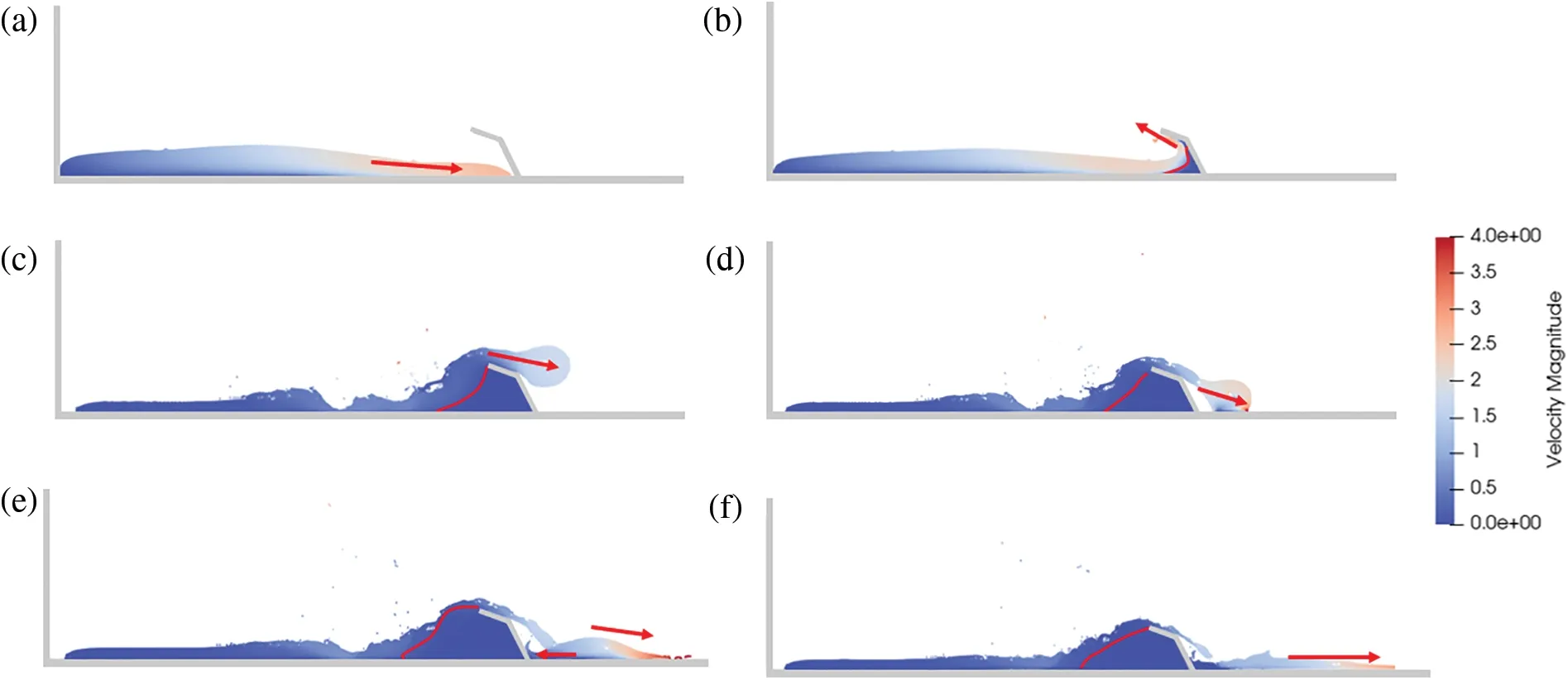
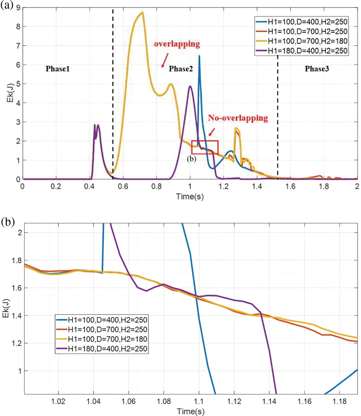
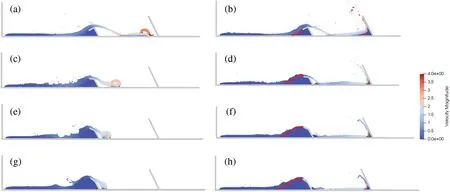
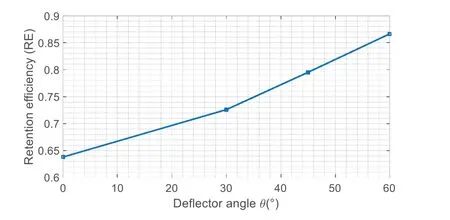
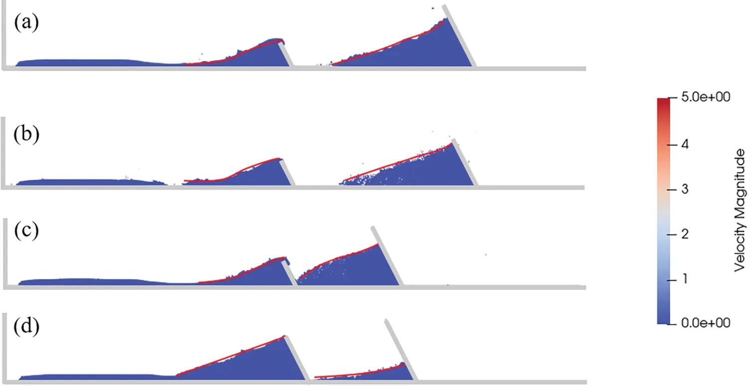
The above model is singular in the static state when= 0.Therefore, this study used a cutoff shear rate ofcutoff= 0.1 s-1to prevent singular viscosity at zero shear rates [49].Here,ηcutoffis the cutoff viscosity when The dam break test reported by a previous study [50] was first used to calibrate the proposed numerical models.Fig.3 shows the geometry of the dam break test and monitoring locations H1 and H4.Additionally, the physical and rheological parameters of the test fluid are listed in Table 2.As mentioned in the description of the rheological model in the Subsection 2.2,the debris flow viscosity is calculated byηapp=+K.When the power-law exponentN= 1 and yield stressτy= 0,the HB model can be converted to the Bingham model. Table 2: Physical and rheological parameters used in dam break test Figure 3:Dam break model test The simulated results obtained by the proposed model were compared to the experimental results and are presented in Figs.4 and 5.Fig.4 mainly compares the relative flow elevation (h/H), which varied with non-dimensional time (t∗=), of the numerical and experimental results; H represents the initial height of the dam break.Figs.4a and 4b shows the temporal evolution of the flow levels at the given locations H1 and H4 for an initial heightH=0.3 m,which agrees well with the literature data,including the arrival of the primary wave at location H4.The relative load pressure(P/ρgH)varied with the non-dimensional timet∗,and the pressure sensor was located at the right end of the box with a height of 0.03 mm to monitor the pressure variations.Fig.5 shows that the impact pressure load was slightly higher than the experimental data when the initial height of the dam break wasH=0.3 m,and approximately the same whenH=0.6 m. Figure 4: (a) Fluid level elevations at location H1 and (b) Fluid level elevations at location H4,compared with literature data[50] Figure 5: (a) H = 0.3 m: impact pressure from pressure sensor, and (b) H = 0.6 m: impact pressure from pressure sensor,compared with literature data[50] Unlike water, when a viscous debris flow collides with an obstacle, the flow velocity decreases dramatically,leading to an approximately triangular zone of a fluid at rest forming upstream of the obstacle.This deposited zone is referred to as a“dead zone”in mudflow[51].The ensuing flow mounts this dead zone and expends part of its energy before hitting the barrier[1,24,52].When the barrier’s retention capacity is reached,an overflow effect occurs:the debris flow material begins to escape from the barrier and flows forward through the barrier crest[53].A dimensionless parameterDF=LDZ/Ldis introduced to quantitatively analyze the dead-zone formation [54];LDZis the length of the dead zone, andLdis the deflector length.Throughout the fluid–structure interaction, the dead zone acts as a buffer layer,possibly aiding in the dissipation of the flow’s kinetic energy and the redirection of its momentum[55].Upon reaching the flume base,the viscous fluid exhibits a tendency to flow back,which is very different to the behavior of a dry granular material(Fig.6). Figure 6:Schematic diagram of viscous debris overflow barrier(a)before and(b)after impact on flume base;(c)dead-zone formation To gain a better understanding of the deflector’s robustness against disasters,the kinetic energyEKis introduced as a measure of the system’s dynamic behavior,as follows: Here,Npdenotes the total number of fluid particles within the interaction domain in the monitored domain (ranging betweenx= 1.05 m andx= 1.15 m); the termmirefers to the mass of particlei;|ui|denotes the velocity magnitude of particlei.The retention efficiency(RE)of the barrier is used to quantify the proportion of the viscous flow particles retained by the upstream barrier[56].In Eq.(17),mretentionis the mass of viscous flow particles upstream of the barrier,andmtotalis the total mass of the released viscous flow particles. This study investigated the effect of single and dual-barrier systems with a deflector angle of 26°on viscous debris flow.To investigate the interaction between the viscous debris flow and the dualbarrier system,upstream and downstream barriers with different heights(B/h=2–5),and the distance between the barriers,were simulated.Here,hrepresents the maximum flow depth in the open channel test.Detailed information is provided in Table 3. Table 3: Numerical investigation scenarios At the upstream barrier position,the flow thickness and front flow velocity were measured in the open-channel test(H0-WD)to calculatehmax=0.042 m(shown in Fig.7). Figure 7:Open-channel test(t=0.625 s) Based on the simulation results,the rest of this paper focuses on the overflow pattern and pile-up mechanisms, and discusses the energy dissipation under the influence of the deflector angles, dead zone,and retention ability of the barrier with different barrier heights and location setups. Fig.8 illustrates the dynamic behavior of viscous flow overflow with and without deflectors.A single barrier with a height of 100 mm and deflector angles ranging from 0° to 60° was considered.Orthogonal deflectors(0°)and 30°deflectors caused the viscous flow to overflow the barrier quickly,resulting in higher velocity magnitude.The distance traveled by the overflow and its points of impact on the channel base are defined as the launch length(D);the flow launch angle is defined as the angle between the overflow direction and the horizontal line[12].In this study,the viscous flow reached the base of the slope(approximatelyt=1.05 s)of each scenario to calibrate the launch angle and length for subsequent investigations. Figure 8:Overflow mechanisms:(a)without deflector(H10-WD2:t=1.05 s);(b)deflector angle θ =0°(H10-D0:orthogonal deflector,t=1.025 s);(c)deflector angle θ =30°(H10-D30:t=1.075 s);(d)deflector angle θ =45°(H10-D45:t=1.05 s);(e)deflector angle θ =60°(H60-D0:t=1.1 s) Deflectors with larger angles lead to a shorter launch length and larger launch angles when the viscous debris flow overflows the barrier and lands on the flume base.As shown in Fig.9a,the launch length decreased from 1.845 to 1.273 m as the deflector angle increased from zero to 45°.However,the effect was less pronounced when the deflector angle exceeded 45°.The launch length of a barrier without deflectors(1.715 m)is marginally shorter compared with that of orthogonal deflectors(0°).The launch angle increased from approximately 20°to 35°as the deflector’s angles(ranging from 0°to 60°)increased(Fig.9b). Figure 9:Influence of deflector angles on(a)launch length and(b)launch angle In Fig.10, the size of the dead-zone area markedly increases with the introduction of a barrier equipped with deflectors.Additionally, the dimensionless length of the dead-zone is positively correlated with the deflector angles.When the deflector angle exceeds 30°,the dimensionless length of the dead-zone increases significantly,reaching values above 3.5. Figure 10:Influence of deflector angles on dimensionless length of dead-zone(DF) Fig.11 illustrates the general evolution of overflow kinetic energy with various deflector angles,which can be categorized into three phases.Before impacting on the barrier,there is a kinetic energy peak in the process, owing to the acceleration of the debris flow.Phase 2 involves the dissipation process of the kinetic energy induced by the deflectors.Compared with barriers with deflectors,the kinetic energy of barriers without deflectors immediately increases, indicating a significant increase in the particle velocity.However, barriers with deflectors experience a period of zero kinetic energy when entering Phase 2 of dissipation,primarily because the deflectors directly intercept the impacting particles and then create a dead zone. Figure 11:Evolution of overflow kinetic energy with different deflector angles The overflow velocity magnitude and viscous debris direction are largely influenced by the deflector angles.The barrier with orthogonal deflectors exhibits a dissipation process similar to that of a barrier without a deflector, leading to the longest launch length.Although the 45° deflector significantly reduces the launch length, its capability of energy dissipation is inferior to that of the 60°and 30°deflectors within the monitored section.In the H10-D45 test program(Fig.12),the dead zone starts to form when the flow impacts the barrier,and gradually grows and controls the overflow behavior observed aroundt=1 s of the viscous flow after the flow–barrier interaction and dead-zone formation.The dead-zone characteristics are discussed below. Figure 12: Flow–barrier interaction mechanisms under deflector angle θ = 45° (H10-D45): (a) t =0.425 s;(b)t=0.475 s;(c)t=1 s;(d)t=1.05 s;(e)t=1.1 s;(f)t=1.5 s The energy dissipation of the dual-barrier system exhibits characteristics similar to the three stages observed in the single barrier structure described earlier (Fig.13).The energy accumulation phase follows a pattern of initial increase and subsequent decrease.Compared with the upstream barrier with a height of 100 mm,the barrier with a height of 180 mm exhibits a zero-energy zone owing to the formation of a larger dead zone.The distance between barriers affects the energy dissipation process.A shorter distance results in a larger proportion of particles flowing back to the upstream barrier with higher velocity.In contrast,the downstream barrier with a height of 180 mm effectively intercepts the released viscous debris flow. The barrier height, barrier location, and deflector angles greatly influence the control of the dynamic behavior of viscous flow.As shown in Fig.14,increasing the height of a single barrier from 100 mm(B/h=2.38)to 250 mm(B/h=5.95)leads to the complete retention of viscous debris flow and dead-zone formation. Figure 13:Evolution of overflow kinetic energy under different conditions of dual-barrier system:(a)global;(b)detail Figure 14:Pile-up mechanism of barrier with height of 250 mm(H10-WD1:t=3.45 s) In this study,barriers with heights of 100 and 180 mm were investigated at distances of 400 and 700 mm,respectively.When the upstream barrier was equipped with deflectors,a downstream barrier height of 250 mm could intercept the entire debris volume in four test programs.The deflector angle influenced the formation of the dead zone near the deflectors, with larger angles resulting in more pronounced ramp-like dead zones.The results are presented in Fig.15, illustrating that the dead zone serves as cushion layer at the upstream barrier.The impact of the overflowing debris flow on the downstream barrier results in the formation of dead zones with different sizes.Particularly, the upstream barrier equipped with an orthogonal deflector exhibits the highest momentum,leading to the rapid interception of viscous flow by the downstream barrier. Figure 15:Pile-up mechanisms under influence of deflector angles:H10-D0-H25(a)t=1 s,(b)t=1.075 s; H10-D30-H25: (c) t = 1.025 s, (d) t = 1.25 s; H10-D45-H25: (e) t = 1.05 s, (f) t = 1.35 s;H10-D60-H25:(g)t=1.075 s,(h)t=1.45 s Larger deflector angles can effectively retain a larger amount of debris flow.Fig.16 shows that the deflector’s debris flow interception capability increases and then stabilizes starting from approximately 1.5 s.As shown in Fig.17,when the deflector angle θ ≥45°,more than 80%of the released debris flow can be retained,indicating strong mitigation capability. Figure 17:Influence of deflector angle on retention efficiency In a dual-barrier system without deflectors,the ramp-like dead zones become steeper as the height of the upstream barrier increases(Fig.18).Although the barrier distance is reduced by 42.9%to 300 mm,the downstream barrier retains the highest debris flow volume.Compared with the single barrier with retention efficiency(Fig.19),the upstream barrier with a height of 180 mm intercepted over 90%of the debris flow,exceeding the interception of approximately 40%achieved by the upstream barrier with a height of 100 mm. Figure 18: Pile-up mechanisms: (a) H10-WD-H25: t = 2.34 s; (b) H18-WD1-H25: t = 3 s; (c) H18-WD2-H25:t=3 s;(d)H18-WD-H25:t=3 s Figure 19: Time series of upstream barrier retention efficiency under different dual-barrier system conditions This study investigated the interaction of viscous debris flow with barriers that have different deflector angles,and the impact of a dual-barrier system with different barrier heights and distances.The main conclusions are as follows: (1) The interaction between viscous debris flows and barriers is largely determined by the deflector angles.Specifically, a deflector angle below 45° forms shallow ramp-like zones,promoting a thick and high-speed overflow downstream.The dimensionless length of the dead zone increases significantly when the deflector angle exceeds 30°.Moreover,the overflow mechanisms vary owing to the intricacies of viscous debris flows,with back-flows becoming more obvious when the flow velocity increases and the launch length decreases.There are three stages of energy in the dissipation process:the cumulative phase,interaction phase,and plateau phase. (2) The barrier’s height and downstream positioning profoundly influence the effectiveness of single barriers in retaining flows.For instance,a barrier height decreasing from 250 to 180 mm cuts the retained flow volume by approximately one tenth,while a height reduction to 100 mm decreases the volume by approximately 40%.In dual-barrier systems,the spacing between the barriers also affects the dead-zone formation. Although this study provides insights into the role of deflectors and dual-barrier systems against debris flows,further research into other influencing factors and the three-dimensional effects during viscous debris flow–structure interactions is required. Acknowledgement:The authors thank the editor and the reviewers for their help to improve the quality of our manuscript. Funding Statement:This study was supported by the National Natural Science Foundation of China(Grant Nos.42120104008 and 42207198). Author Contributions:Conceptualization,Y.H.and D.F.;methodology,B.L.and H.S.;formal analysis,B.L.and H.S.; investigation, B.L.; writing—original draft preparation, B.L.; writing—review and editing,Y.H.and D.F.;visualization,B.L.;supervision,D.F.;funding acquisition,Y.H.and D.F.All authors have read and agreed to the published version of the manuscript. Availability of Data and Materials:The data sets used and analysed during this study are available from the corresponding author upon reasonable request. Conflicts of Interest:The authors declare that they have no conflicts of interest to report regarding the present study.2.3 Model Validation
3 Results and Discussion

3.1 Overflow Pattern and Energy Dissipation

3.2 Pile-Up Mechanism and Retention Efficiency


4 Conclusion
 Computer Modeling In Engineering&Sciences2024年5期
- Computer Modeling In Engineering&Sciences的其它文章
- Wireless Positioning:Technologies,Applications,Challenges,and Future Development Trends
- Social Media-Based Surveillance Systems for Health Informatics Using Machine and Deep Learning Techniques:A Comprehensive Review and Open Challenges
- AI Fairness–From Machine Learning to Federated Learning
- A Novel Fractional Dengue Transmission Model in the Presence of Wolbachia Using Stochastic Based Artificial Neural Network
- Research on Anti-Fluctuation Control of Winding Tension System Based on Feedforward Compensation
- Fast and Accurate Predictor-Corrector Methods Using Feedback-Accelerated Picard Iteration for Strongly Nonlinear Problems
