An impact sensitivity assessment method of spacecraft based on virtual exterior wall
Runqiang Chi, Yuyan Liu, Diqi Hu, Baojun Pang
Hypervelocity Impact Research Center, Harbin Institute Of Technology, Harbin,150080, China
Keywords: Sensitivity OD/M Spacecraft Virtual exterior wall
ABSTRACT The impact sensitivity assessment of spacecraft is to obtain the probability of spacecraft encountering the OD/M (orbital debris or meteoroid), which is a prerequisite for survivability assessment of on-orbit spacecraft.An impact sensitivity assessment method of spacecraft based on virtual exterior wall was proposed to improve the computational efficiency.This method eliminates determination of the outermost surface elements of the spacecraft before generating the debris rays, which are assumed to originate from a non-concave virtual wall that completely wraps the spacecraft.The DistMesh method was adopted for the generating of the virtual wall to ensure its mesh quality.The influences of the sizes,mesh densities, shapes of the virtual wall on the efficiency and accuracy were considered to obtain the best combination of the size and mesh density of the wall and spacecraft.The results of this method were compared with those of S3DE (Survivability of Spacecraft in Space Debris Environment), BUMPER,MDPANTO,ESABASE2/Debris to verify the feasibility of the method.The PCHIP(Piecewise Cubic Hermite Interpolating Polynomial) was used to fit the size vs.flux relationship of the space debris to acquire the impact probability of OD/M with arbitrary size on the spacecraft.
1.Introduction
The exponential growth the space sector experienced in recent years led to an increase of orbital debris threat.According to the U.S.SSN[1](Space Surveillance Network),the number of space objects with sizes larger than 5 cm in LEO(Low Earth Orbit) and 13 cm in GEO (Geosynchronous Orbit) reached 42,000, and the number of cataloged objects larger than 10 cm has exceeded 25,000.The statistical model of European Space Agency's (ESA) Space Debris Office[2]estimates that the number of debris with size of 1-10 cm is about 1 million,and the number of debris with size of 1-10 mm is about 130 million.Aiming at the impacts of hundreds of millions of debris with millimeter size and below,the installation of shielding structures is currently used to protect spacecraft [3].However,adding a bumper inevitably increases the weight of the spacecraft,resulting in an increase in cost.Therefore,it is necessary to evaluate the risk of on-orbit spacecraft during its design process [4].Sensitivity assessment [5] is a prerequisite for survivability assessment of on-orbit spacecraft,and presents the impact probability of OD/M particles on the spacecraft and its components,taking the OD/M as the risk source.
¨Opik[6]was the first to determine the relationship between the probability of collisions particle with planets in the solar system and their orbital parameters.Wetherill [7] extended the ¨Opik equation to the collision with arbitrary orbits and introduced the concept of "spatial density" to make the equation more concise.Kessler and Cour-Palais [8], who applied the equation to the probability calculation of debris impact on satellites, defined the"flux",which is the number of impacts per unit area per unit time.Su and Kessler [9] applied Poisson distribution to collision probability calculation based on the flux.After that, the impact risk assessment software of different countries were all developed based on this method.
NASA (National Aeronautics and Space Administration) developed the BUMPER [10], a systematic OD/M risk assessment software.The finite element method is used to discretize the spacecraft geometry model into mesh elements.The BUMPER calculates the number of impacts for each element and sums the number of particles of the entire spacecraft,and finally determines the impact probability by Poisson statistics.EAS's assessment software, ESABASE2/Debris[11],is also based on flux and Poisson distribution for impact probability calculation, but differs from BUMPER in the evaluation.ESABASE adopts Monte Carlo method to pick random points on the spacecraft geometric surface and performs weighting according to the flux input from the OD/M engineering model,sequentially, the impact expectation number of each component encountering OD/M is further determined.EMI's PIRAT [12] (Particle Impact Risk and vulnerability Analysis Tool)combines a debris flux model with the Sch¨afer-Ryan-Lambert ballistic limit equation[13] (SRL-BLE), which accounts for the inherent shielding of components positioned behind the spacecraft structure wall.The failure probabilities as a function of mission time of individual satellite components are calculated.The analysis conducted on the case study shows the overall vulnerability index of the spacecraft decreased by 18%[14],on the premise of increasing the finite mass(about 2 kg).With the support of ESA,PIRAT has developed a large number of software interfaces [15], which greatly improve the efficiency of modeling in the process of evaluation.
Stokes [16] studied the potential for genetic algorithms to optimize protection on a realistic unmanned spacecraft.By using a software tool called SHIELD, his results showed that optimal protection solutions can be found when taking into account other competing engineering requirements such as the need to retain spacecraft mass balance.The best protection strategy is not only to improve the spacecraft structure but also to well arrange the internal equipment.
Trisolini [17] presented the development of a vulnerability assessment model,which relied on a fully statistical procedure: the debris fluxes are directly used combining them with the concept of vulnerable zone, avoiding the random sampling the debris fluxes.It modeled the interaction between the components and the secondary debris cloud through basic geometrical operations, considering mutual shielding and shadowing between internal components.
The S3DE [18] (Survivability of Spacecraft in Space Debris Environment) was developed by the team of the Hypervelocity Impact Research Center in Harbin Institute of Technology (HIT).The calculation process of S3DE is similar to that of BUMPER.It is worth mentioning that three institutions have their own OD/M engineering models: NASA's ORDEM [19] (Orbital Debris Engineering Model),ESA's MASTER[20](Meteoroid and Space Debris Terrestrial Environment Reference) and HIT's SDEEM [21] (Space Debris Environment Engineering Model),and they are expected to output data in the same format for risk assessment.
In this paper, we propose an impact sensitivity assessment method of spacecraft based on virtual exterior wall to improve the computational efficiency.This method eliminates determination of the outermost surface elements of the spacecraft before generating the debris rays,which are assumed to originate from a non-concave virtual wall that completely wraps the spacecraft.In Section 2,the sensitivity assessment process based on virtual exterior wall by using DistMesh [22] method is presented in detail.The influences of different sizes,mesh densities,and shapes of the virtual wall on the efficiency and accuracy were considered in Section 3 to determine the best matching relationship of each parameter.The feasibility and accuracy of the method were verified by comparing with other impact risk assessment software by using the "benchmark"cases in the IADC protection manual in Section 4.Finally,the PCHIP[23] method was used to acquire the impact probability of OD/M with arbitrary sizes on the spacecraft in Section 5.Section 6 presents the conclusion.
2.The sensitivity assessment process based on virtual exterior wall
The virtual exterior wall refers to a geometry covering the entire spacecraft in the process of sensitivity analysis, as shown in Fig.1.Before hitting the spacecraft,the OD/M particles must pass through the virtual wall.Therefore, it can be assumed that the OD/M particles are emitted inward from the virtual wall in the form of rays.The directions of rays are discretized according to the flux direction distribution from the environment engineering model.In view of the characteristics of the OD/M distribution,the direction of orbital debris can be considered as parallel to the local horizontal plane of the spacecraft, and the direction of spacecraft velocity is 0°, and there are 36 directions in the range of -175°to 175°, with an interval of 10°.While the direction of meteoroid can cover the whole celestial sphere direction of the spacecraft.The elevation angle ranges from -85°to 85°, the azimuth angle ranges from -175°to 175°, there are 18×36 directions with an interval of 10°.
The sensitivity analysis process based on the virtual exterior wall is shown in Fig.2.The initial rays originate from virtual wall elements and spread in a radial pattern in all directions, as shown in Fig.3.Half of these rays are directed outward from the spacecraft.Therefore, the outward rays should be eliminated to improve the calculation efficiency.Hence,the intersection of rays and spacecraft elements is determined,and the intersecting rays and elements are picked for the next step.Combined with the flux outputs of the environment model, the number of OD/M carried by rays is calculated to obtain the expected number of the spacecraft components encountering OD/M impacts.Finally, the impact probability of each component is obtained according to Poisson's distribution formula.
2.1.Generating the virtual wall based on DistMesh
As the source of OD/M, the elements of the virtual wall are required to have high homogeneity in size and density.Due to the various geometric of spacecraft,if HYPERMESH and other meshing software are used for virtual wall generating, it is difficult to maintain the homogeneity of the elements, which may lead to inaccurate result, and cumbersome operation.Therefore, we propose an adaptive generating method of virtual wall based on DistMesh, which adaptively matches the corresponding virtual wall according to the geometry of spacecraft.
DistMesh [25] is an automatic program for finite element meshes generation developed by Per-Olof Persson and Gilbert Strang from UC Berkeley and MIT mathematics departments respectively.DistMesh uses analytic expressions to describe the geometry and while it is not applicable for complex model, it is suitable here,which requires a regular geometry such as a sphere or ellipsoidal surface.
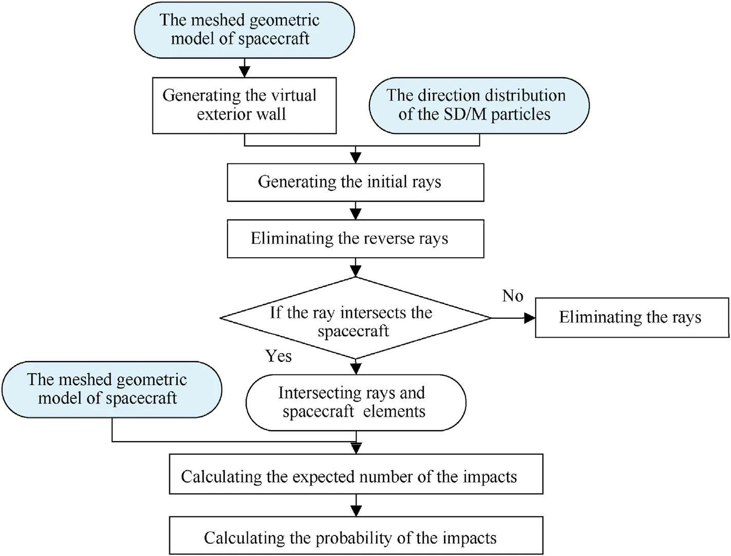
Fig.2.The sensitivity analysis process based on the virtual exterior wall.
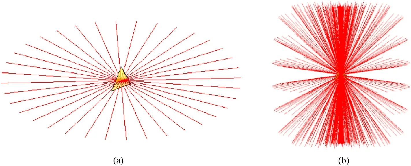
Fig.3.The origination of the initial rays.Yellow triangles are the virtual wall elements.
The mesh generation process of DistMesh method is shown in Fig.4.The first step is creating a uniform distribution of nodes within the bounding box of the geometry.The next step is removing all nodes outside the desired geometry according to the distance function.Then the code enters the main loop, where the mesh is regenerated by Delaunay triangulation algorithm to determine the node position and topology.Moreover, the method proposes a "force-displacement" relationship algorithm in the process of mesh optimization, in which the triangular mesh is analogous to a two-dimensional truss structure.The nodes are the nodes of the truss,and the sides of the elements are considered as truss bars, and the forces deform the bars to move the nodes.The node coordinates can be expressed as
The force of each bar depends on the difference between its current length and the ideal length, as shown in Eq.(1).
where thekis the stiffness coefficient of the simulated bar.WhenFi>0, increasing the length of the bar.For all nodes within the geometry, ideally there is an equilibrium written as:
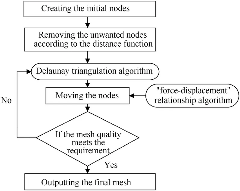
Fig.4.The mesh generation process of DistMesh method.
In order to improve the efficiency,liis allowed to be slightly larger thanl0, and the ratio is usually set to 1.2.
The quality of the generated virtual wall is evaluated by the variance of elements area δS.The ratio of the whole wall area and the average area of elements,Rs, is the independent variable, the largerRsmeans denser mesh.That the area δSvaries with the ratio of areaRsis shown in Fig.5.The variance of area δSdecreases linearly with the increase ofRs, and the δSis within 10-5.Consequently,the mesh generated by DistMesh have good homogeneity,and the higher the mesh density, the higher the homogeneity.
Finally, we can automatically generate spherical or ellipsoidal virtual walls that completely wrap the spacecraft based on the spacecraft geometry as shown in Fig.6.
2.2.Generation of initial rays
The virtual wall elements,directions of OD/M particles,and the spacecraft geometric model determine the starting positions of the rays, the directions of the rays, and the rays to be rejected,respectively.The ray is emitted from the center of the element,the starting point (O) of the ray can be obtain by coordinates (xi,yi,zi,i=1,2,3)of the element nodes(Ni,i=1,2,3),and is expressed as
The normal vector of the element can be given as
Because of the uncertainty of the nodes order of the element,the normal vector in Eq.(5) does not necessarily point to the interior, as shown in Fig.7.Here, the dot product of the normal vector and thevector can determine it.If the dot product is less than 0, the opposite vector is taken as the normal vector of the element.
The direction of the ray is determined by the azimuth (α) and elevation (β) of the discrete direction of the OD/M.In the orbital coordinate system, the direction of the ray(D)can be expressed as
When the particle is the orbital debris, =0 , and the range of azimuth is 0-360◦.Similarly,the dot product of the normal vector of the element and the direction of the particle is used to determine whether the ray direction points interior.If the dot product is less than 0,the direction is discarded.The expected number of particles carried by each ray is obtained from Eq.(7).
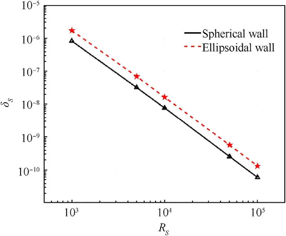
Fig.5.The variance of area varies with the ratio of area.
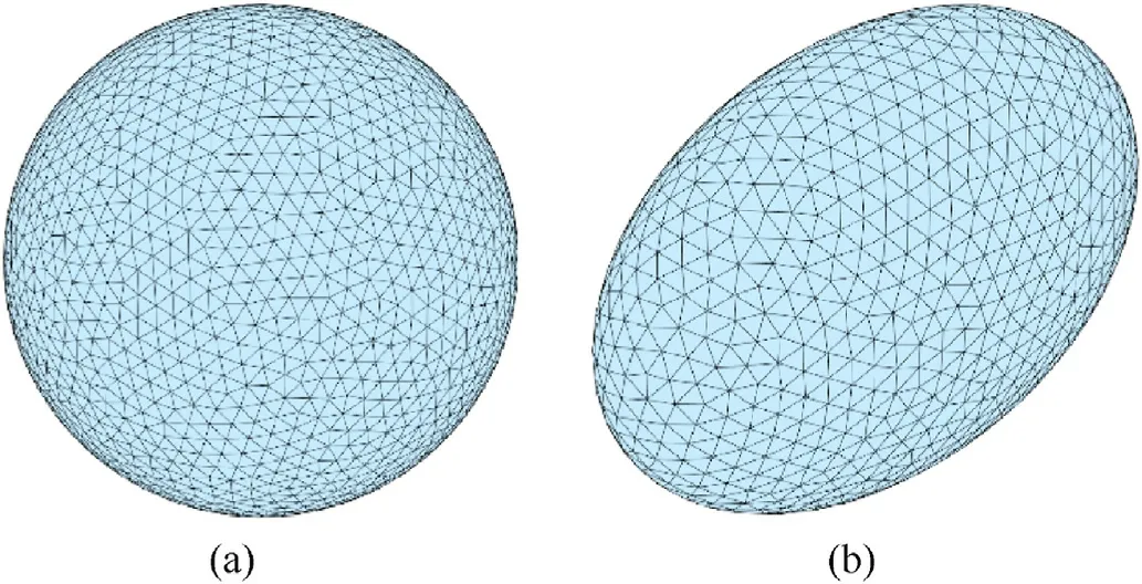
Fig.6.The mesh of the virtual exterior wall.
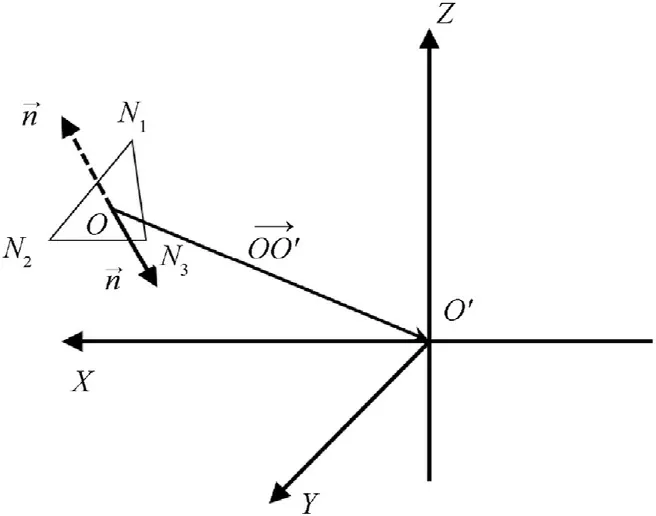
Fig.7.The normal vector of the element.
where the cross-sectional area can be expressed by the area of element (S').
where θ is the angle between the velocity direction of the particle and the normal vector of the element, as shown in Fig.8.
2.3.Intersection of the ray and the element of spacecraft
The M¨oller-Trumbore method[24]is used to determine whether the ray intersects with the element of spacecraft, and the ray is represented by Eq.(9) wheretis the coefficient.
Similarly, the element of spacecraft consists of three nodes (Vi,i= 0,1,2).The point (T) inside the element of spacecraft can be described by Eq.(10), as shown in Fig.9.
Then,Tcan be expressed as
When the ray intersects the element as shown in Fig.10, the pointTis both on the ray and the element,which means it satisfies both Eq.(9) and (12), and satisfiesu≥0, v ≥0,u+ v ≤1.
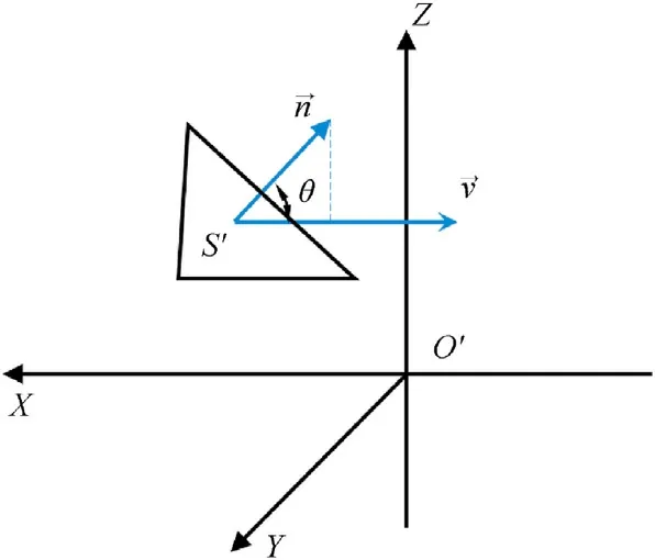
Fig.8.The direction of the ray emission from the center of the element in the orbital coordinate system.
LetE1=V1-V0,E2=V2-V0,P=O-V0,Eqs.(2)-(14)can be written as
The solution tot,u, v can be obtained as Eqs.(2)-(16) with Cramer's Rule.
LetR=D×E2,S=T×E1, according to the mixed product equation.
Eqs.(2)-(16) can be changed as
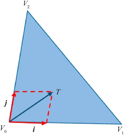
Fig.9.The point (T) inside the element of spacecraft.
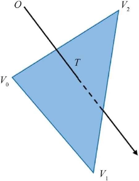
Fig.10.The ray intersects with the element of the spacecraft.
The values oft,u, v can be obtained from Eqs.(2)-(18).Intersecting rays and spacecraft elements can be selected according to these conditions:t>0,u≥0,v ≥0,u+v ≤1.In addition,a ray may intersect with more than one element of the spacecraft, and the value oftrepresents the depth of the intersecting elements in the direction of the ray.Here,the element with the smallest t-value is taken and the intersection of the ray with the spacecraft element is shown in Fig.11.
2.4.Impact probability
In terms of a spacecraft in the OD/M environment, the impact events satisfy the Poisson distribution, due to impact events between the spacecraft and OD/M that are independent of each other.Assuming that the probability ofNimpact event isp(N), it can be expressed as
where λ is the expected number of the impacts,the probability with no impact can be written as
Then the probability with at least one impact event can be written as
It should be noted that the results presented in this paper are basically the expectation of impacts rather than the probability of impacts.Because when the number of impacts is greater than 1,the probability is very consistent,which cannot reflect the distribution characteristics of impacts.
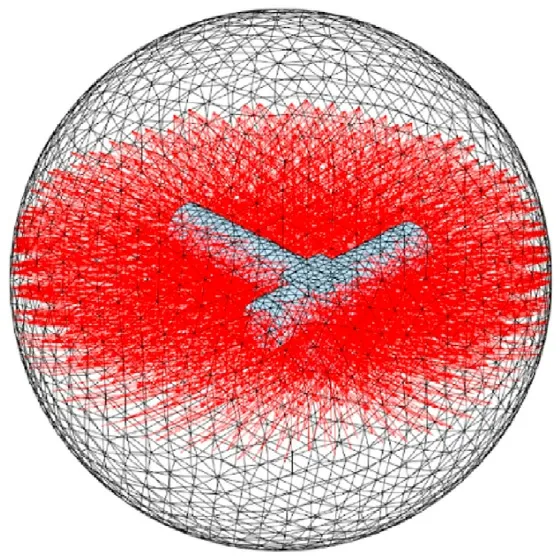
Fig.11.The intersection of the ray with the spacecraft element.
3.The characteristic parameters of the virtual exterior wall
The ratio of the size of the virtual exterior wall to the size of the spacecraft and the mesh density of the wall will affect the accuracy of the spacecraft sensitivity assessment.Since rays have fixed directions and intervals, the distance between the wall (V) and the spacecraft(E)directly affects the number of the rays intersect with the spacecraft, as shown in Fig.12(a).By increasing the virtual exterior wall mesh density,as shown in Fig.12(b),the effect of the distance between the two on the accuracy can be reduced.However,increasing the mesh density of the virtual wall will lead to the decrease of the efficiency.The influences of the sizes, mesh densities,and shapes of the virtual wall and spacecraft on the efficiency and accuracy were considered to determine the best matching relationship of each parameter.
The fluxes of OD/M at Chinese Space Station(CSS)orbit(Table 1)were given by SDEEM2019 as listed in Table 2, In addition, the direction distribution of OD/M were also given by SDEEM2019.The meteoroids flux is mainly concentrated in the range of elevation 0-45◦and azimuth - 30◦to 30◦, as shown in Fig.13.And the distribution of orbital debris flux with azimuth is shown in Fig.14,which is mainly concentrated in the range of ±70◦-90◦.
3.1.Influence of the size ratio and mesh density
Triangular-mesh spherical spacecraft with a cross-sectional area of 1 m2was used to analyze the influence of the size ratio of the wall and spacecraft and mesh density of the virtual wall on the accuracy, as shown in Fig.15.According to the definition of fluxes,the theoretical values of the expectation of impacts on the sphere encountering with OD/M of different sizes are equal to the values of fluxes with corresponding sizes in Table 2.
The influence of virtual wall parameters on the calculation accuracy was analyzed with reference to the expectations of the impacts by OD/M with size larger than 10 μm,and the results are shown in Figs.16-18.Different mesh densities can be achieved by modifying the size of the virtual wall element under a defined wall size.
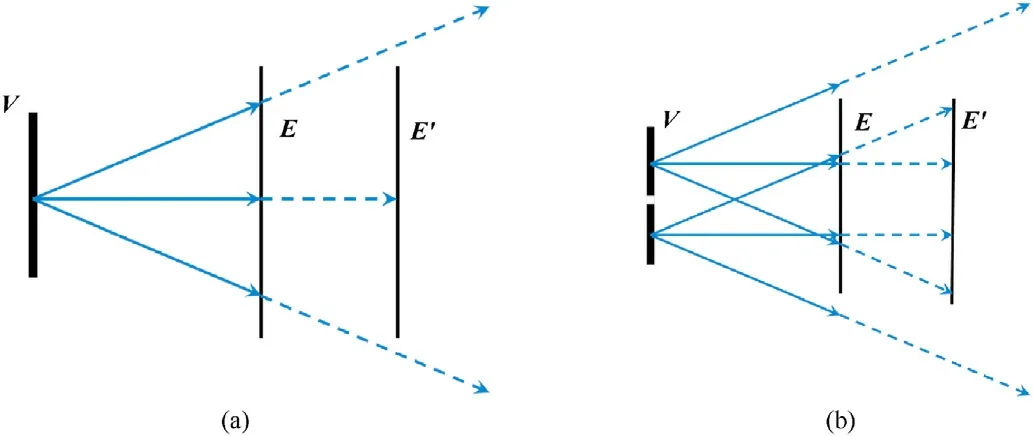
Fig.12.The characteristic parameters of the virtual exterior wall.

Table 1The parameters of CSS orbit [26].
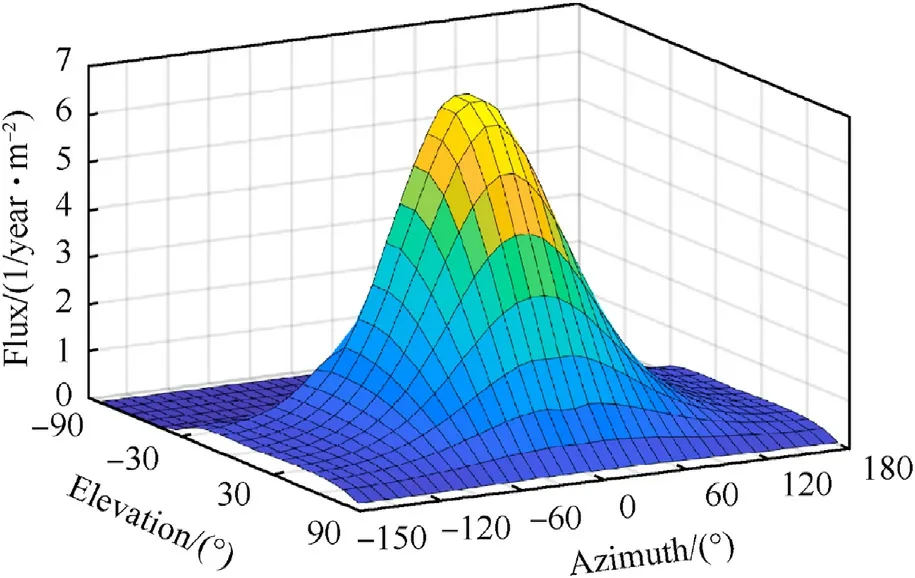
Fig.13.Distribution of meteoroid flux with azimuth and elevation.

Fig.14.Distribution of orbital debris flux with azimuth.
It can be seen that when the element size is less than 0.5 m,the curves of all size ratios tend to be smooth.The maximum bias of the orbital debris is 3.32%, when the size ratio is 2.5 and the element size is 0.4 m, and the maximum bias of the meteoroid is 2.72%,when the size ratio is 1.5 and the element size is 0.5 m.When the element size is less than 0.2 m,the errors of the expectations of the orbital debris and meteoroid impacts are kept within 0.8% and 0.23%,respectively.The increasing in mesh density at this point has limited improvement in accuracy with a great cost in efficiency.
The size ratio has inconsistent effects on the orbital debris and meteoroid as shown in Fig.18.When the size ratio is less than 2 or more than 3,the mesh density places more influence on the results of orbital debris,while for meteoroids,the mesh density has less and less influence on the results as the virtual exterior wall size increases.
Combined with the results in Figs.16-18, considering the efficiency and accuracy, the virtual exterior wall used in the subsequent calculation should be 2-3 times as large as the outer tangent circle of the spacecraft geometry.
3.2.Relationship between mesh density of the wall and spacecraft
As mentioned before, OD/M particles are emitted by the virtual wall elements as rays, each ray carries the number of the particlesthat pass through the element,which in turn simulates the impacts on the spacecraft.According to the definition of flux,the virtual wall element size will directly affect the number of particles carried by the ray.Taking orbital debris impacting spacecraft as an example, as shown in Fig.19.Where the V is the virtual wall element, E is the spacecraft geometry model, and the arrow represents the ray carrying orbital debris particles.Theoretically the orbital debris particles passing through the virtual wall element may impact on the spacecraft geometry model elements 1, 2 and 3.However, the method assumes that the particles are emitted from the center of the virtual wall element, in which way particles passing through this virtual wall element can only actually impact on the spacecraft element 2.Although it does not affect the impacts expectation of the spacecraft as a whole,it brings about a problem that the impacts expectation of some elements of the spacecraft are more concentrated, which affects the accuracy of particle distribution.

Table 2The fluxes of the OD/M at the CSS orbit.
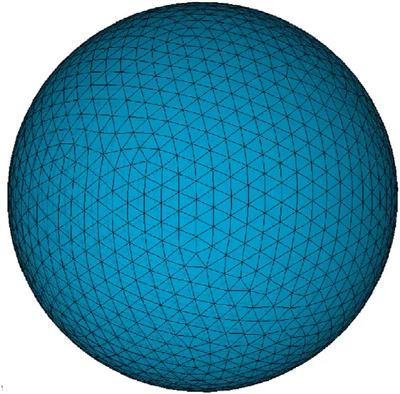
Fig.15.The geometric model of the sphere spacecraft and the elements size is 0.06 m
In order to obtain the best matching relationship between the element size of the spacecraft and element size of the virtual wall,the wall element size was modified under the fixed spacecraft element size.Figs.20-23 illustrate the pseudo-color map of the spacecraft impacts expectation with different sizes of virtual wall elements.Similarly,the spacecraft geometry model is a sphere with a cross-sectional area of 1 m2and the elements size is 0.06 m.The radius of the virtual wall is twice the size the size of that in the spacecraft,and the wall element sizes are 1/3,1/2,1 and 2 times as large as the spacecraft element, and the virtual wall element sizes are 0.02 m,0.03 m,0.06 m and 0.12 m.From the distribution of the expectation of impacts on the spacecraft surface in the figures,the impacts are more concentrated on some elements of the spacecraft when the virtual wall element size is 0.06 m or 0.12 m.However,when the element size is 0.02 m and 0.03 m, the impacts expectations are relatively evenly distributed, and the distribution is consistent with the distribution of OD/M in Figs.13 and 14.
According to Eqs.(2)-(7), the expectation of the element impacts is proportional to its area.Since the mesh division is not absolutely uniform, the expectations of some elements deviate from their neighboring elements.As shown in Fig.24, the spacecraft impacts density expectation can better catch the distributions of OD/M in Figs.13 and 14.
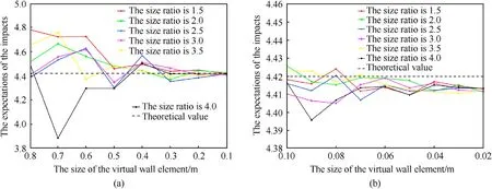
Fig.16.The expectations of the impacts by orbital debris for different size ratio and size of the virtual wall element, the dashed line is the theoretical value.
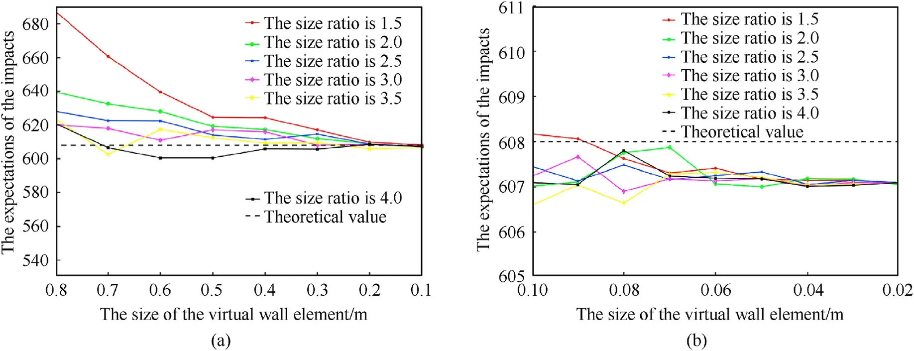
Fig.17.The expectations of the impacts by meteoroid for different size ratio and size of the virtual wall element, the dashed line is the theoretical value.
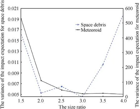
Fig.18.The variance of the impact expectation for different element sizes with different size ratios.
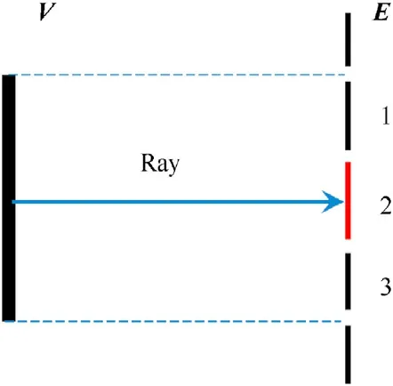
Fig.19.The ray representation of the orbital debris impacting the spacecraft model.
For further analysis, the influence of the element size of the spacecraft on the accuracy was taken into account.And the spacecraft geometry model is still a sphere with a cross-sectional area of 1 m2and the elements size is 0.2 m as shown in Fig.25.Similarly, the results of virtual wall with different sizes of the elements are given in Fig.26.
Compared with the results of spacecraft model with 0.06 m element size, the spacecraft model with 0.2 m element size has an overall lower impacts expectation.Considering the maximum bias compared with the theoretical data, the expectations of spacecraft model with 0.2 m element size are lower, at 2.53% and 2.79%respectively formeteoroids and orbitaldebris,whereasthosewith the 0.06 m element size are 0.18%and 0.34%.This is due to the fact that meshing the model with different element sizes brings different bias to the final mesh model, and the difference can be clearly seen between Figs.15 and 25.In addition,the surface area of the geometric model after division is 3.9915 m2for the former and 3.8952 m2for the latter,which are 0.21%and 2.62%smaller than the surface area of the sphere,respectively.This is highly consistent with the bias.
In general,the finer the mesh of the spacecraft geometry model is, the higher its computational accuracy becomes, but it needs to sacrifice computational efficiency.The element size of the virtual wall should be less than half of the element size of the spacecraft,which can guarantee that the impacts expectation distribution is in line with the reality.
3.3.Influence of the shape of the virtual wall
In practical engineering, the spacecraft is often much longer in one inertial principal axis direction than in the other two directions, as shown in Fig.27.
In order to get the influence of the shape of the virtual wall,spherical and ellipsoidal virtual walls were used in sensitivity assessment.According to the conclusion of subsection 3.2,the size of the spherical virtual wall is twice larger than that of the outer tangent circle of the spacecraft, i.e., the radius of the wall is 6 m.Similarly,the three axes of the ellipsoidal virtual wall are twice the size of the maximum size of the spacecraft in the direction of the three inertial main axes.They all have an element size of 0.08 m,and the final number of the spherical wall elements is 212,300,while that of the ellipsoidal wall elements is 54,468.The results were compared with those from the S3DE,which applies the panel method, as shown in Table 3.
The results of virtual wall method are generally smaller than those of the S3DE,and the largest difference occurs within 3%when the main body of the spacecraft encounters orbital debris.The relative differences of the results of spherical wall and ellipsoidal wall are almost identical.Nevertheless, the assessment of the spherical wall and the ellipsoidal wall took 2187 s and 426 s at the same computer, respectively.Therefore, the use of ellipsoidal virtual wall for impact sensitivity assessment substantially improves the calculation efficiency with guaranteed precision.
In view of the difficulty to keep the area of every element consistent in triangular meshing, the pseudo-color map of spacecraft impacts expectation density was used to illustrate the distribution of the OD/M impact,as shown in Fig.29.In the±Y-direction of the spacecraft,there is shielding effect between the main part of the spacecraft and the solar wings, resulting in the impacts expectation densities of some elements significantly smaller than those of other elements.Combining the flux direction distribution as shown in Figs.13 and 14, the orbital debris is mainly concentrated in the±Y-direction of the spacecraft,and the meteoroids are concentrated in the+X-direction of the spacecraft(the direction of the velocity) as illustrated in Figs.29 and 28.And, the results of both methods are highly similar.
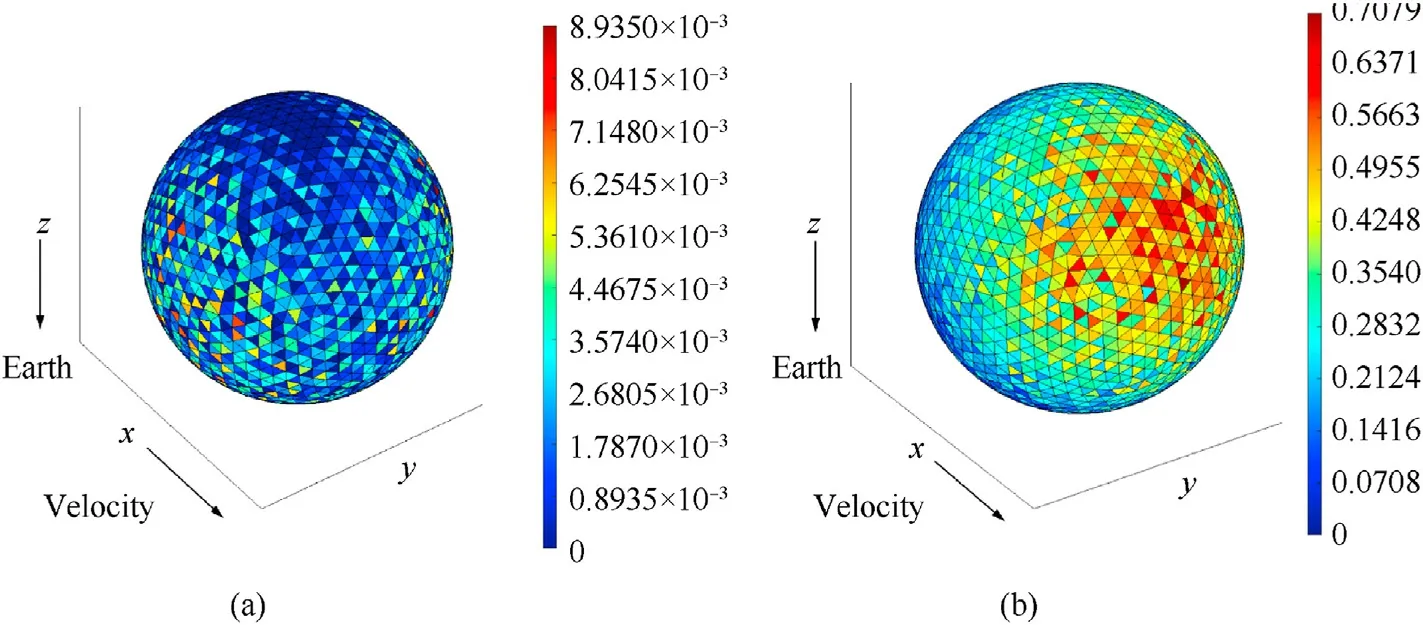
Fig.20.The pseudo-color map of spacecraft impacts expectation.The size of the virtual wall element is 0.12 m.
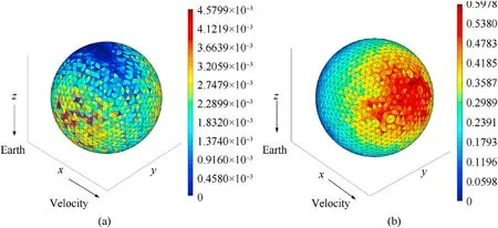
Fig.21.The pseudo-color map of spacecraft impacts expectation.The size of the virtual wall element is 0.06 m.
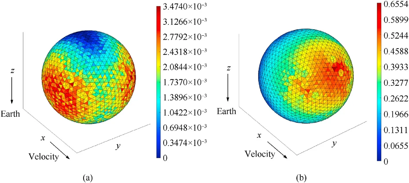
Fig.22.The pseudo-color map of spacecraft impacts expectation.The size of the virtual wall element is 0.03 m.
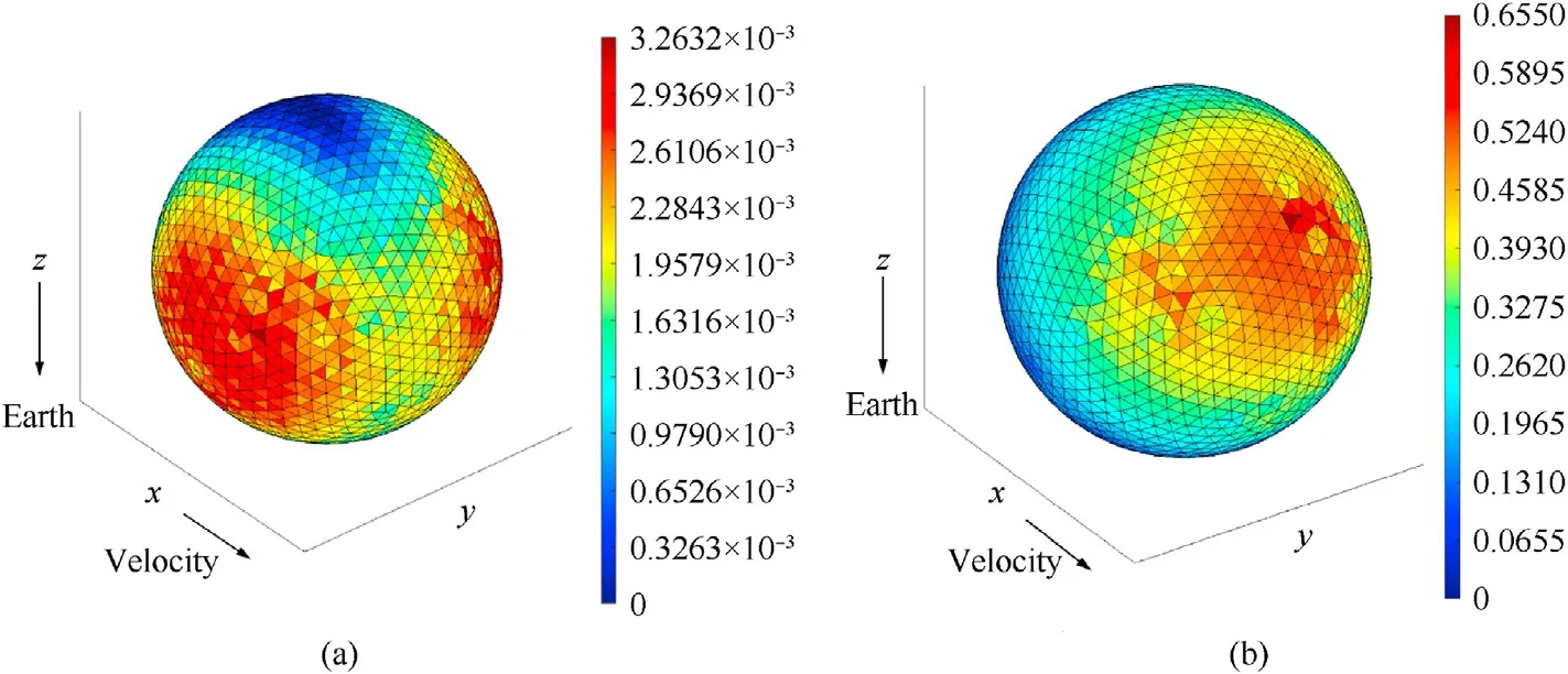
Fig.23.The pseudo-color map of spacecraft impacts expectation.The size of the virtual wall element is 0.02 m
4.Validation with calibration cases
The three calibration models specified by IADC (Inter-Agency Space Debris Coordination Committee) as shown in Fig.30 and mission parameters listed in Table 4 were used as input for sensitivity assessment.The orbital debris cumulative fluxes were calculated by ORDEM 2000 and the meteoroid cumulative flux was obtained by NASA SSP-30425 model, as listed in Table 5.The assessment results of the virtual wall method were compared with those of the S3DE, and cross-referenced with the resultant data from BUMPER, MDPANTO and ESABASE3.0/Debris.
4.1.Compared with the S3DE
The sensitivity assessments of three calibration cases were carried out by using S3DE and the method illustrated in this paper,the results are listed in Table 6.
From Table 6,the results of the panel method and the virtual wall method are very close,and the difference between the two is mostly less than 1%.In addition, the difference between the results of two methods and the theoretical values in Table 5 is less than 0.5%.
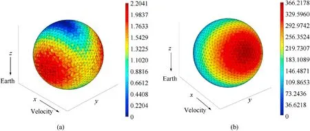
Fig.24.The pseudo-color map of spacecraft impacts expectation density.The size of the virtual wall element is 0.02 m.
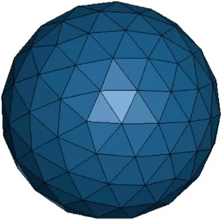
Fig.25.The geometric model of the sphere spacecraft, and the elements size is 0.2 m
Figs.31 and 32 show the impacts expectation density distribution of the simple space station encountering OD/M of different sizes for the two methods.Meteoroid of both sizes are mainly concentrated on the windward side, while the distributions of orbital debris of different sizes are inconsistent.From the density distribution of the expectation of orbital debris impacts, the impacts expectation on the part of the-X-axis module that is shielded by the-Y-axis module is significantly less than the rest of the-X-axis module, indicating that both methods can adequately reflect the shielding effect between the components of the spacecraft.Overall,the results of two methods reflect the same distribution of OD/M.
4.2.Compared with other software
The results of the sensitivity assessment by the virtual wall method were cross-referenced with the data from the IADC [4]manuals for BUMPER,MDPANTO,and ESABASE2/Debris.Tables 7-9 show the expectations of the impacts by OD/M on the three calibration models of cube, sphere and simple space-station, respectively.The results of the impacts expectation of the three calibration models encountering OD/M larger than 0.1 mm and larger than 1 cm are compared, respectively.
In terms of the different particle types, the expectations of orbital debris impacts calculated by virtual wall method are larger than those of the other three software, and the relative deviation from ESABASE2/Debris is also greater than the other two software.Nevertheless,the expectations of meteoroids impacts calculated by virtual wall method are smaller than those of the other three software, and the relative deviation from BUMPER is greater than the other two software.
Compared with the results of different software, the deviation for different size particles is relatively stable.Taking BUMPER as an example, the relative deviations of the virtual method are around 4%for all three cases of orbital debris larger than 0.1 mm,and those are less than 1%for all three cases of orbital debris larger than 1 cm,and those are about 8%for all three cases of meteoroid at two sizes.

Fig.26.The expectations of the impacts by OD/M for different size of the virtual wall element and spacecraft element.
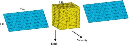
Fig.27.The spacecraft geometry model.

Table 3Comparison of the impacts expectations for different methods.
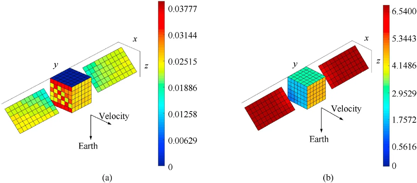
Fig.28.The pseudo-color map of spacecraft impacts expectation of S3DE.
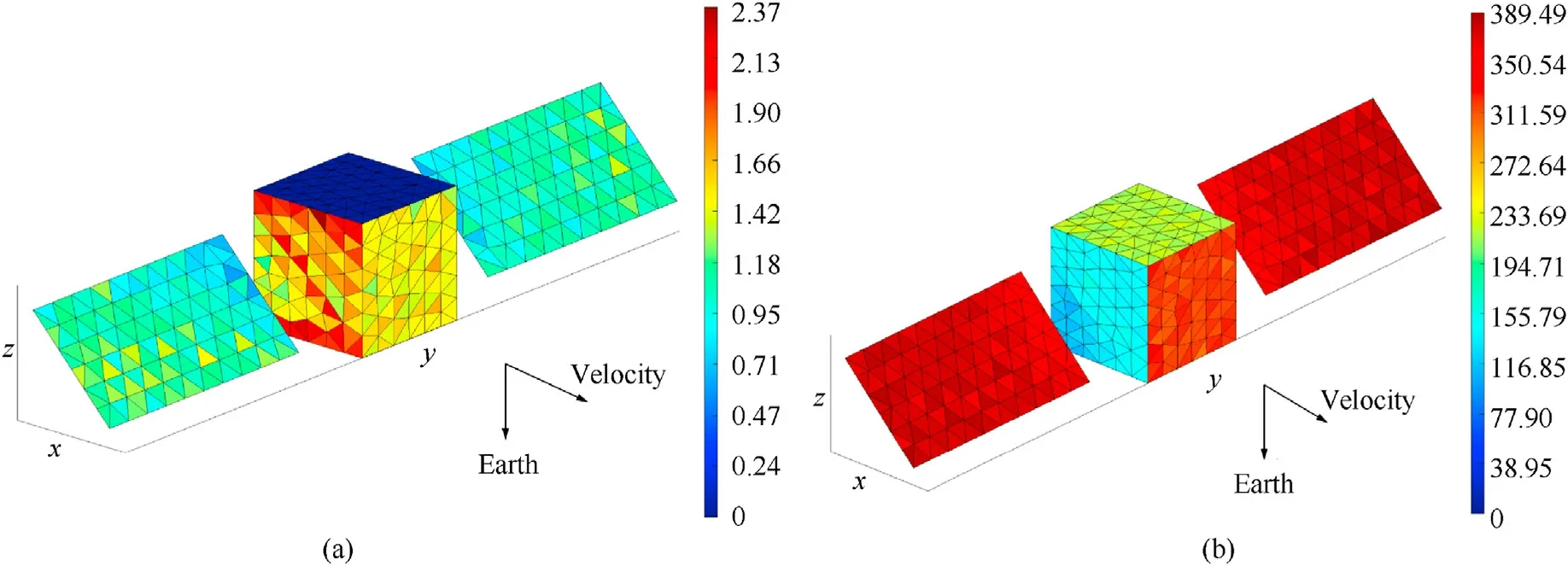
Fig.29.The pseudo-color map of spacecraft impacts expectation density of virtual ellipsoidal wall method.
From the impacts expectations of sphere in Tables 8 and 5, the deviation between the results of the virtual wall method and the theoretical value is relatively smaller than that of the other three software.From Tables 7 and 9, it can be seen that the deviation of the virtual wall method may originate from the environmental data.Since the environmental data in this paper are obtained by calculation,it is not known whether there is any difference from the input of the other three software and the range of the deviation cannot be certain, which may lead to the uncertainty of the deviation for the final sensitivity assessment.

Fig.30.Geometries of three calibration models [4]:

Table 4Mission parameters calibration models.

Table 5The cumulative fluxes of the OD/M for different sizes.

Table 6The impacts expectations of three calibration cases by using different methods.
The density distributions of OD/M impacts expectation in Fig.33.The pseudo-color map of cube impacts expectation density of virtual wall method are similar to the distribution of the simple space-station in Fig.32, where the impacts of meteoroids and orbital debris larger than 1 cm are concentrated on the windward side,while the orbital debris larger than 0.1 mm are distributed on the left and right sides of the direction of velocity.In the three sets of pseudo-color images,the expectation density distributions of the impacts of meteoroids are more even than those of orbital debris.This is due to the fact that meteoroids are discretized not only in azimuth but also in elevation (36×18 directions), while orbital debris is only discretized in azimuth(36 directions),which leads to a slight large error,and the accuracy can be improved by increasing the discrete directions and the mesh density of the geometric model.
5.The impacts expectation of OD/M of arbitrary size
The OD/M environmental engineering model outputs debris data in the form of a cumulative discrete data according to ≥10 μm,≥100 μm,≥1 mm,≥1 cm and ≥1 m.Although MASTER can output data with denser OD/M size, but the process of survivability assessment needs to get the fluxes of arbitrary size interval, the usual method is to interpolate and fit the discrete data.ORDEM 2000 uses the cubic spline interpolation method to obtain the orbital debris flux of arbitrary size.And except ESABASE2, which adopts linear interpolation, all other risk assessment software applies cubic spline interpolation.However, in practice, cubic spline interpolation method will cause a non-monotonic interpolation curve, which is contrary to the definition of cumulative flux.Therefore, this paper adopts PCHIP (piecewise cubic Hermite interpolating polynomial) method to obtain the flux of OD/M at arbitrary size, which can ensure the monotonicity of the fitted curve as well as the accuracy.
Construct segmented cubic Hermite interpolation polynomials for the interpolation.The functiony=f(x) at nodesa=x0≤x1≤x2···≤xn=bhas the function valuesyi=f(xi),and the derivative valuemj=f'(xj)(j=0,1,···,n).A segmented cubic Hermite interpolation function can be constructed so that it satisfies Eq.(22) and Eq.(23), andIn(x) is a cubic polynomial in each interval [xk,xk+1](k= 0,1,2,…,n- 1).
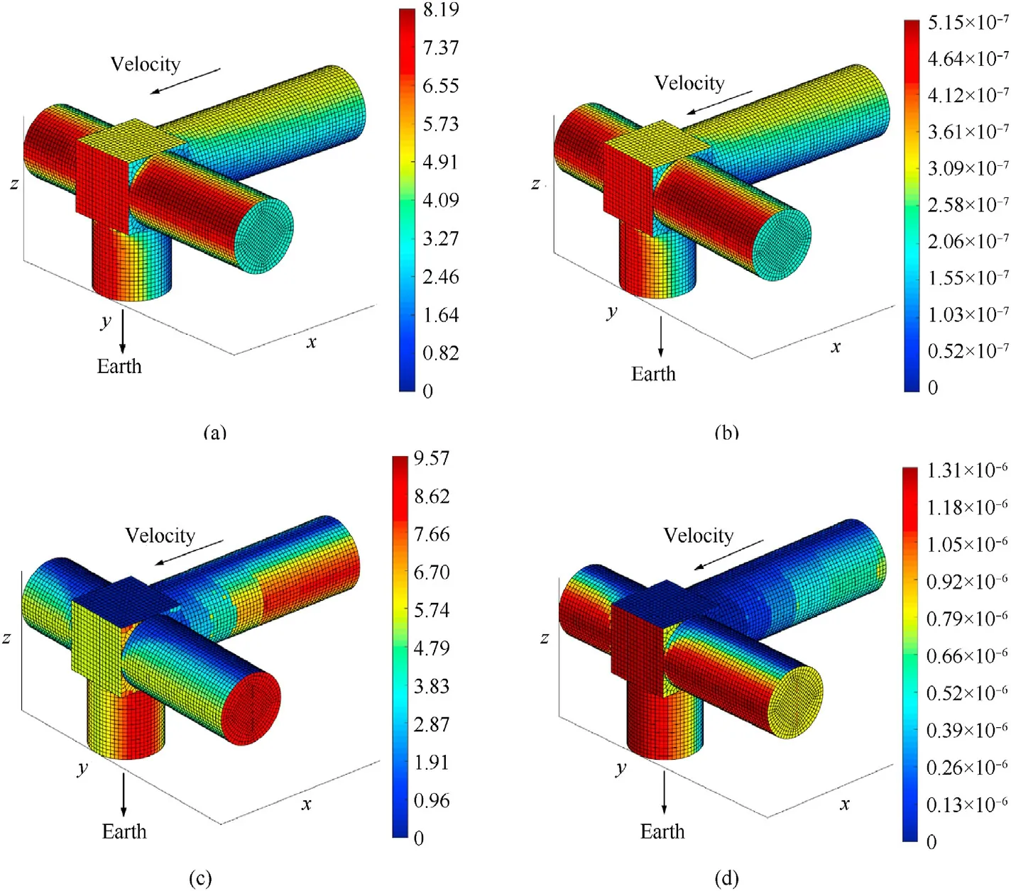
Fig.31.The pseudo-color map of simple space-station impacts expectation density of S3DE (panel method).
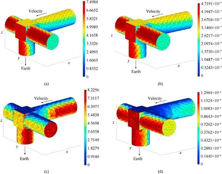
Fig.32.The pseudo-color map of simple space-station impacts expectation density of virtual wall method.
In(x) satisfiesn=1 Hermite interpolation polynomial at [xk,xk+1], it can be expressed as

Table 7The expectations of the impacts by OD/M on the cube.

Table 8The expectations of the impacts by OD/M on the sphere.

Table 9The expectations of the impacts by OD/M on the simple space-station.
where
The segmented cubic Hermite interpolation functionIn(x) can be obtained from Eqs.(24)and(25),and in the whole interval[a,b],In(x) can expressed by the interpolation basis function as
where the interpolation basis functions αi(x) and βi(x) are expressed as
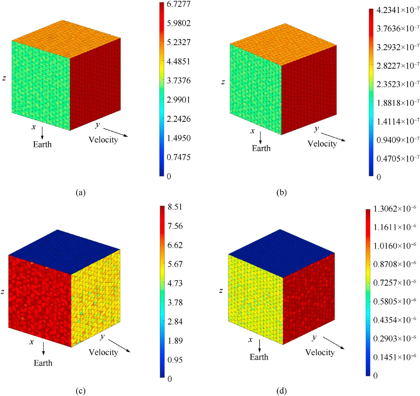
Fig.33.The pseudo-color map of cube impacts expectation density of virtual wall method.
Using the data in Section 4 and the sphere in the calibration cases, the impacts of OD/M larger than 0.5 mm and larger than 5 mm size were analyzed, and the impacts expectation density results are shown in Table 10 and Fig.35.Comparing Figs.35(c)and 35(d), and Figs.34(c) and 34(d), it can be seen that, unlike other sizes of debris which are either concentrated on the windward side of the satellite or symmetrically distribute on the left and right sides of the direction of velocity,the orbital debris larger than 5 mm has a more even distribution of the impact expectation on the windward side and both sides of the velocity direction.

Table 10The impacts expectations of OD/M of arbitrary sizes.
6.Conclusions
An impact sensitivity assessment method of spacecraft based on virtual exterior wall was proposed.By generating a non-concave geometry surrounding the spacecraft, and emitting rays from the elements of the geometry to simulate incoming particles impact the spacecraft, and performing the intersection between rays and spacecraft judgment, and then the expectation and probability of the spacecraft impacted by OD/M are obtained.The main conclusions are as follows:
(1) This paper expounds the principle of sensitivity analysis based on virtual exterior wall, and shows the feasibility of this method.Using DistMesh to generate virtual exterior wall mesh, on the one hand, improves the convenience, but also ensures the quality of mesh.The Moller-Trumbore method is used to realize the simulation of particle impact on spacecraft, and provides a basis for further analysis of the impact sensitivity of spacecraft internal components.The influence of the virtual exterior wall characteristic parameters on the accuracy was analyzed, and the best matching relationship between the characteristic parameters of virtual exterior wall and the spacecraft geometry model were obtained.
(2) The method is cross-verified with spacecraft risk assessment software such as S3DE, BUMPER, MDPANTO and ESABASE2/Debris by using IADC calibration cases.The errors between the results of this method and those of other software are within 10%,which verifies the feasibility and accuracy of the method.
(3) The PCHIP method is used to interpolate and fit the size-flux relationship of orbital debris,and the sensitivity analysis for impacts of particles of arbitrary size were achieved.
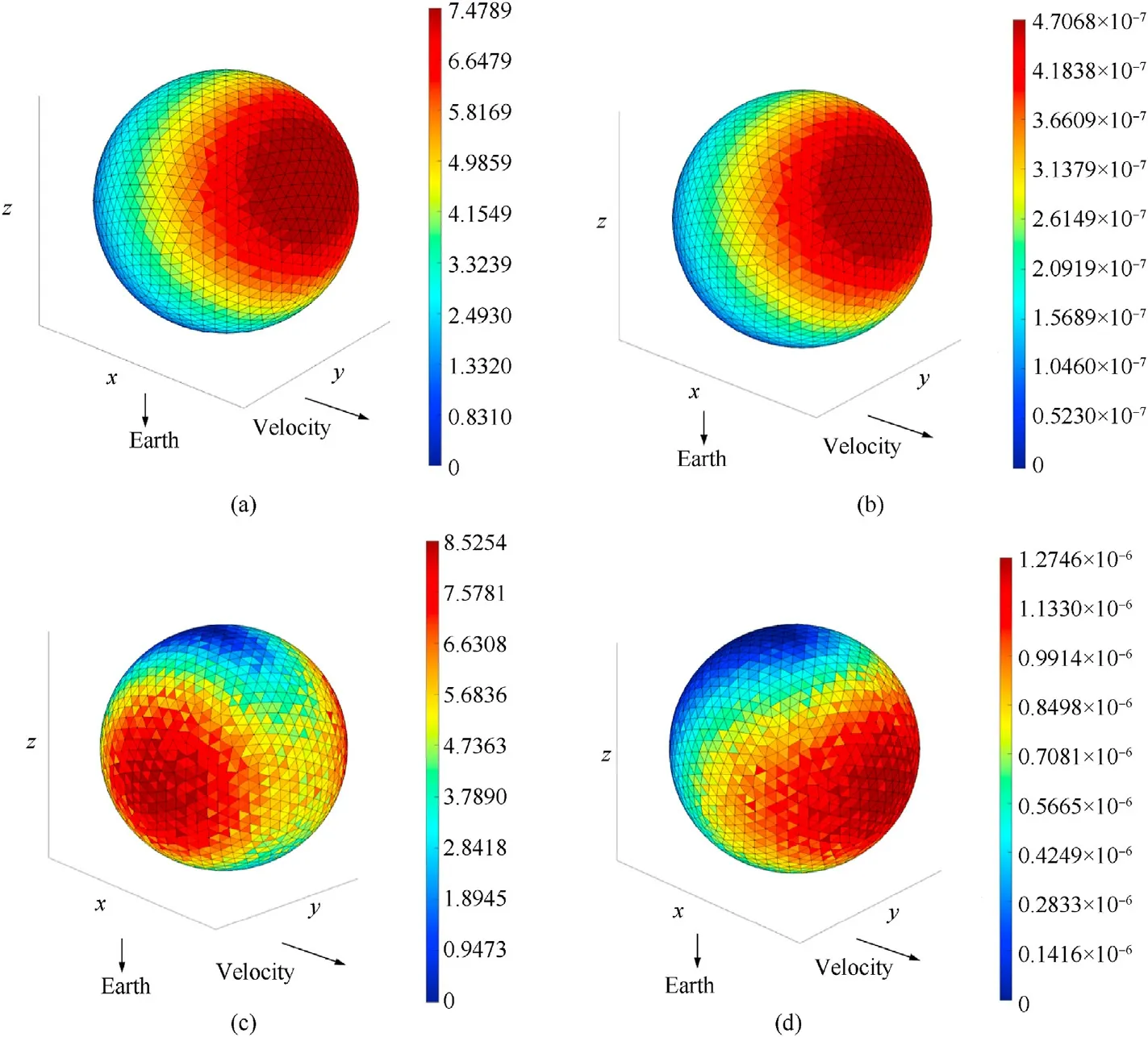
Fig.34.The pseudo-color map of sphere impacts expectation density of virtual wall method.
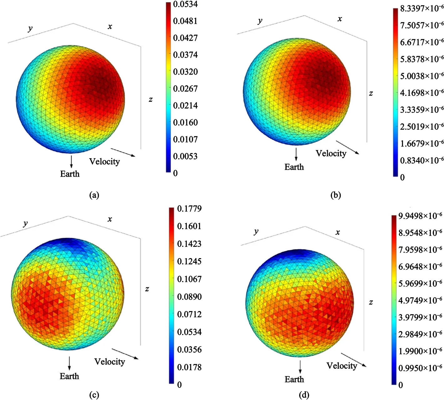
Fig.35.The pseudo-color map density of any size OD/M impacts expectation on sphere.
Declaration of competing interest
The authors declare that they have no known competing financial interests or personal relationships that could have appeared to influence the work reported in this paper.
- Defence Technology的其它文章
- The interaction between a shaped charge jet and a single moving plate
- Machine learning for predicting the outcome of terminal ballistics events
- Fabrication and characterization of multi-scale coated boron powders with improved combustion performance: A brief review
- Experimental research on the launching system of auxiliary charge with filter cartridge structure
- Dependence of impact regime boundaries on the initial temperatures of projectiles and targets
- Experimental and numerical study of hypervelocity impact damage on composite overwrapped pressure vessels

