
Creep constitutive model considering nonlinear creep degradation of fractured rock
2024-02-17 05:41WangChunpingLiuJianfengChenLiangLiuJianWangLudLiaoYilin
矿业科学技术学报 2024年1期
Wang Chunping ,Liu Jianfeng *,Chen Liang ,Liu Jian ,Wang Lud ,Liao Yilin
a Beijing Research Institute of Uranium Geology,Beijing 100029,China
b CAEA Innovation Center for Geological Disposal of High-Level Radioactive Waste,Beijing 100029,China
c State Key Laboratory of Hydraulics and Mountain River Engineering,Sichuan University,Chengdu 610065,China
d School of Architecture and Civil Engineering,Xihua University,Chengdu 610039,China
Keywords:Fractured rock Damage Creep Beishan granite Geological disposal
ABSTRACT Stability analysis of underground constructions requires a model study of rock masses’long-term performance.Creep tests under different stress conditions was conducted on intact granite and granite samples fractured at 30° and 45° angles.The experimental results indicate that the steady creep strain rates of intact and fractured rock present an exponential increase trend with the increase of stress level.A nonlinear creep model is developed based on the experimental results,in which the initial damage caused by fracture together with the damage caused by constant load have been taken into consideration.The fitting analysis results indicated that the model proposed is more accurate at identifying the full creep regions in fractured granite,especially the accelerated stage of creep deformation.The least-square fit error of the proposed creep model is significantly lower than that of Nishihara model by almost an order of magnitude.An analysis of the effects of elastic modulus,viscosity coefficient,and damage factors on fractured rock strain rate and creep strain is conducted.If no consideration is given to the effects of the damage,the proposed nonlinear creep model can degenerate into to the classical Nishihara model.
1.Introduction
For underground projects such as high-level radioactive waste geological disposal and salt cavern gas storage,the surrounding rock plays a crucial role in the long-term stability and safety of the project.Due to the long-term geological tectonic movement of rocks,there are inevitably random distribution of micro-pores and cracks of different shapes in the rock mass.In addition,in the process of underground construction,the surrounding rock may experience the expansion of fractures or pre-existing fractures,leading to the formation of excavation damage zones,which will cause the strength degradation of surrounding rock and has adverse effects on the disposal of radioactive waste or storage of energy [1,2].What’s more,it should be noted that after the engineering excavation,under the continuous action of surrounding rock stress,micro-cracks will continue to expand and lead to further expansion of the excavation damage zone[3].The engineering practice shows that even if the rock stress level is lower than the rock failure stress level,the cracks in the rock will continue to expand,which leads to the continuous development of the excavation damage zone and the instability of the surrounding rock [4].Therefore,studying the long-term mechanical characteristics of fractured rock mass,and establishing a creep constitutive model that can describe its long-term mechanical behaviour,are crucial for the long-term stability and safety of underground engineering projects.
The creep behaviour of host rock is of special interest for underground structures such as underground storge of natural gas or crude oil and geological disposal repository of high-level radioactive waste.In plenty of studies,creep experiments have been carried out exploring the long-term deformation of host rock,as well as its corresponding creep model that reproduces long-term deformation across the host bedrock [5–8].Based on the creep test results of Tuzköy rock salt,Özs¸en et al.[9] proposed an empirical mathematical model to explain the creep behaviour.For descripting the full stage creep of rocks,Kamdem et al.[10] used a new fractional calculus approach and proposed a new variable fractional order rheological model.For sandstone samples containing a single fissure (fissure angles: 15°,30°,45°,60°,and 75°),Wang et al.[11] conducted triaxial creep tests to reveal the timedependent behaviour of fissured sandstone,and established a damage bond model by combining Kachanov damage theory and a linear parallel bonded model.Li et al.[12] proposed a nonlinear model consisting of a Maxwell body,a Kelvin body and a damageplastic element,which can well represent the creep process of sandstones.The main research object in these studies is intact sample,and researches on the creep constitutive model for fractured rock samples are actually not much seen.However,fractures in host rock are unavoidable in the underground engineering.It is crucial to investigate fractured rock’s long-term performance over time in the feasibility analysis of underground structures.
The experimental investigation has led to the development of a variety of creep constitutive models,that may be categorized into three groups: component model,empirical model,and mechanism-based creep model (mesoscopic physical model).Despite its intuitive concept and clear physical meaning,the component model has attracted more research and application than other models,but it still has many shortcomings in dealing with nonlinear rheological problems and extending one-dimensional constitutive equation to three-dimensional state.Therefore,many scholars set up a nonlinear element and combined it with the traditional element for a complete description of rock creep’s three stages [13–15].Zhou et al.[16,17] set up a variable-viscosity fractional dashpot to characterize the salt rock damage evolution under constant loading,and a fractional constitutive model was presented for salt rock in accordance with the Nishihara model theory.A plastic constitutive model for circular tunnels was proposed by Kargar [18],which demonstrating good agreement in the comparison between the model results and finite difference method results.Fahimifar [19] presented a new formulation for the excavation of circular tunnels based on Burger’s body.There is a problem,however,with their solutions.Their rheological models require more and complex components,resulting in the solution being more complicated and difficult in popularization and application in the project.What’s more,the creep modelling study is mainly focus on the soft rock with large deformation,such as salt rock [20,21],but less common for hard rock such as granite.
To better understand how host rocks deform over time in the context of discontinuous rock mass,experimental investigations on fractured granite samples (the inclination angles were 30° and 45°)have been put into practice.In the light of these results,a nonlinear creep constitutive model was formulated for fractured rock,by replacing the viscoelastic and viscoplastic bodies in the classical Nishihara model with the damaged viscoelastic body and damaged viscoplastic body.Fractured granite experimental results were used to determine model parameters through fitting analysis.Fitting results showed that,for describing the transient-state,steady-state,and accelerated-state stages of creep deformation,the new proposed model is more appropriate than the Nishihara model.
2.Experimental investigation on fractured rock samples
2.1. Sample preparation and test procedure
In this study,rock samples were obtained from Beishan,an area now recognized as a preferable place to dispose of high-level radioactive waste [22,23].The experimental sample is mediumgrained granodiorite,with a particle density of 2.64 g/cm3,a velocity of 3300 m/s and an average compressive strength of 155.12 MPa.First,according to the standard for test methods of engineering rock mass (GB/T 50266-2013),the rock core sample was machined into standard specimens with a diameter of 50 mm and a height of 100 mm (Fig.1a).By using a special rocksplitting device (Fig.1b),intact granite samples were fractured at 30° and 45° angles,which are exactly the fractured rock samples studied in this research(Fig.1c and d).Fig.1e shows the schematic diagram of the prepared specimen.The center point of the long axis of the fractured plane is located in the middle of the outer surface of the specimen.Based on uniaxial compression test,the average compressive strengths of granite samples with 30° and 45°inclination fractures are 142.76 and 109.86 MPa,respectively.
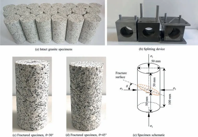
Fig.1.Test specimens and splitting device.
To investigate the creep characteristics of fractured rocks,this paper conducted creep tests on intact granite and granite samples with 30° and 45° inclination fractures.The test equipment used is the rock triaxial rheological test system,as shown in Fig.2.This equipment can provide a maximum axial load of 1500 kN,a rated confining pressure of 0–60 MPa,a rated pore pressure of 0–60 MPa,and a temperature range of room temperature to 200 ℃.The test system is reliable and energy efficient,able to provide a stable pressure environment during rock rheological testing processes.The testing process adopts a stress-controlled loading method,and the axial deformation is measured by two linear variable differential transformers with a maximum range of 12 mm installed on both sides of the sample.In order to avoid the influence of excessive initial closure deformation of pre-existing fractures on the overall deformation of the specimens,a pre-compression of 20 MPa axial pressure is applied to the sample before the test,ensuring the accuracy of deformation test results.
Referring to the in-situ stress distribution characteristics in the Beishan pre-selection area for the disposal of high-level radioactive waste in China,the confining pressure was set at 0 and 10 MPa.Although fracturing can produce granite specimens of the same inclination angle with similar roughness,the individual differences of the specimens will cause significant disturbance to their longterm mechanical characteristics in creep tests over a long period of time.To reduce the interference of individual differences in specimens on the study of creep characteristics,a graded loading method is used to gradually load the axial stress in creep tests of fractured granite specimens.The stress levels are loaded step by step in accordance with 50%,60%,70%,80%,90%,and 100% of the compressive strength σpof fractured granite.Each stress level is maintained for 24 h until the specimen undergoes unstable failure.
2.2. Analysis of test results
During the creep process of fractured granite under graded axial stress loading,the applied axial stresses at each level and the time at which creep failure occurs are shown in Table 1.Sample A-1 failed during the 5th level(90%σp)constant stress loading process,samples A-2 and B-2 failed during the 6th level(100%σp)constant stress loading process,and samples B-1,C-1,and C-2 failed during the constant shear stress loading process of the 4th level(80%σp).

Table 1 Creep testing conditions and final failure time.

Table 3 Parameters of nonlinear creep model of fractured rock under triaxial compression.
Fig.3 shows the complete creep curves and axial strain rates of both the intact granite and the granite samples with 30° and 45°inclination fractures under the conditions of graded axial stress loading.Similar to the results of intact granite,in several stress loading levels before creep failure,the axial strain of the fractured granite exhibits a transient creep stage and steady creep stage.The transient creep stage has a short duration,and the axial strain rate decreases continuously;while the steady creep stage has a longer duration,and the axial strain rate remains almost unchanged.When the stress level increases to the constant loading process of the last stage,the axial strain of the fractured granite enters the accelerated creep stage after experiencing a transient creep stage and a period of steady creep stage,and in this stage,the axial strain rate increases sharply,which leads to rapid failure of the sample.
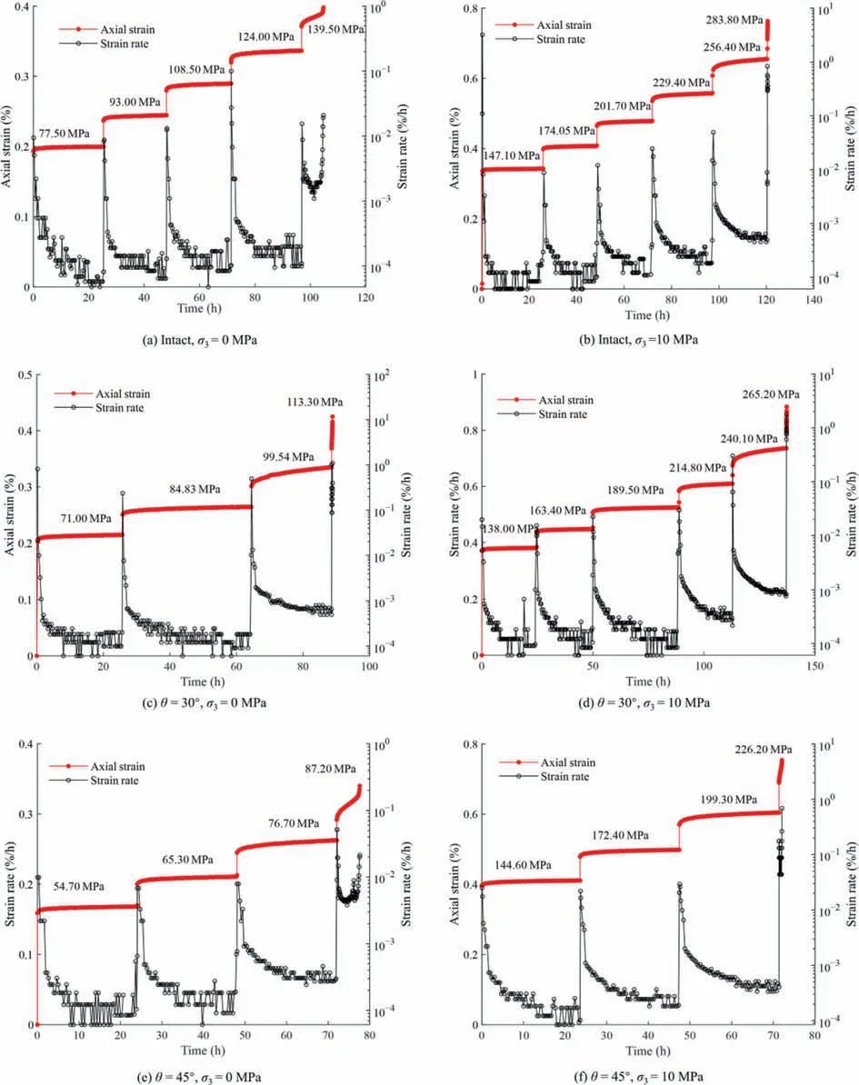
Fig.3.Complete creep curves and axial strain rates.
Calculating the strain rate during the steady creep stage,the steady creep strain rate of intact and fractured granite under different axial stress conditions are obtained as shown in Fig.4.The experimental results show that the steady creep strain rates of intact and fractured rock present an exponential increase trend with the increase of stress level,and the creep rate shows a magnitude growth when the stress level is closer to the creep failure stress of the specimen.In addition,under the same stress conditions,the creep rate of fractured rock is higher than that of intact rock.For fractured rock,the larger the fracture inclination angle is,the higher the shear force on the fracture surface is,and the more easily the specimen is subjected to frictional slip failure.In this study,the average compressive strengths of intact granite and granite samples fractured at 30° and 45° angles are 155.12,142.76,and 109.86 MPa,respectively.When the inclination angel is large enough,failure of the specimen may occur at very low stress level.Similarly,in creep test under the same stress level,the larger the inclination angle is,the more likely the specimen is to have creep failure and the greater the steady creep rate of sample.
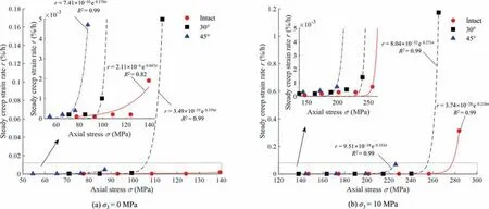
Fig.4.Steady creep strain rate under different axial stress.
Fig.5 shows photographs of intact and fractured granite specimens after creep failure under different confining pressures.For intact granite under uniaxial creep condition,due to the heterogeneity of particle size and structure inside the rock,the tensile stress is locally generated.Under these tensile stresses,microcracks are generated at relatively weak grain boundaries,and brittle failure occurs in the rock,resulting in more vertical cracks along the loading direction (Fig.5a).Under the confining pressure of 10 MPa,the shear failure mechanism begins to control the failure mode of the rock,and the rock failure is transitioned from brittlefailure to shear failure.Due to the confinement effect of the confining pressure,the number of cracks on the surface of the specimen decreased significantly (Fig.5b).
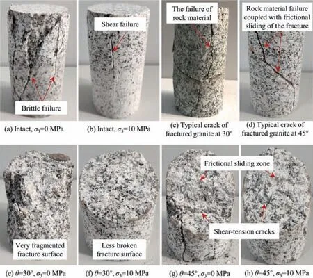
Fig.5.Specimens after creep failure.
For granite samples with 30° inclination fractures,similar to intact rock,brittle splitting failure dominated by tension mainly occurs under uniaxial condition,and shear failure occurs mainly under confining pressure of 10 MPa with a certain angel between the shear failure plane and the maximum principal stress.The failure of rock material is the major controlling factor of the failure of 30° inclined fractured granite.Microcracks first form at weak points of the specimen,and then extend towards both ends of the specimen in the direction of the load.When microcracks extend to the pre-existing fracture surfaces,a portion of the energy is released,resulting in fewer newly formed cracks on the surface of the fractured granite sample compared to intact rock.Whether under uniaxial conditions or under a confining pressure of 10 MPa,the newly formed cracks directly extend through the pre-existing fracture surface to the ends of the sample (Fig.5c).
For the 45° inclined fractured granite,the failure of the specimen is mainly the failure of the rock material,but it is also coupled with partial frictional sliding on the pre-existing fracture surface.The shear stress on the pre-existing fracture surface is relatively high,even approaching the shear strength,but it is still not sufficient to cause complete sliding along the pre-existing fracture surface.Since the two sides of the pre-existing fracture are completely coupled together,a local stress concentration may be formed at the position of the rough and convex particles,leading to the crack initiation and eventually expansion to the end of the sample.Therefore,the newly formed cracks are not directly connected,but are separated by pre-existing fracture surfaces,presenting an inclined‘‘Z” shape (Fig.5d).
In addition to the cracks on the outer surface of the specimen,the pre-existing fracture surface also changes closely related to the failure mode.Under the condition of uniaxial creep,the new main cracks on the fracture surface with an inclination of 30° are mainly tensional cracks,which usually cross the pre-existing fracture surface and divide it into two parts.While more secondary cracks are distributed around the main cracks,resulting in the fracture surfaces being very fragmented (Fig.5e).On the fracture surface with an inclination of 45°,the shear stress is close to the shear strength of the specimen,and the pre-existing fracture tends to slip but is blocked by the protruding particles on the surface.Therefore,there are not only frictional sliding zone,but also shear-tension cracks caused by stress concentration on the pre-existing fracture surface (Fig.5g and h).The new cracks are usually distributed on the long axis of the pre-existing fracture surface close to the end of the specimen.Under the confining pressure of 10 MPa,the occurrence of newly generated micro-cracks was significantly reduced,and the pre-existing fracture surfaces were less broken(Fig.5f and h).
3.Fractured rock creep constitutive model
An often-used component model in geological engineering is the classical Nishihara model,which is consisted of three parts:the Hooke element (H),the viscoelastic body (N/H) and the viscoplastic body(N/St.V) [16],as presented in Fig.6a.Hook element determines the magnitude of the initial strain in the creep deformation process(Fig.6c).The viscoelastic body is adopted to display the viscoelastic behaviour of material in the steady creep stage.In the event that the applied stress goes beyond the limit of the yield stress of material,the viscoplastic body is added to the Nishihara model to demonstrate the viscoplastic behaviour of rock in the process of accelerated growth in deformation.The Nishihara model has some distinct advantages in reproducing the first two stages of deformation over time [24].However,in approaching the tertiary creep region,the Nishihara model still has much limitation.As presented in Fig.6c,the creep rate during the accelerated creep stage simulated by the Nishihara model remains almost constant,which is inconsistent with the actual situation during the experiment where the creep rate sharply increases and strain grows nonlinearly with time after the specimen enters the accelerated creep stage.To demonstrate the full deformation stages in fractured rock,this paper proposes a new nonlinear creep model with the introduction of a damage evolution equation deduced from creep test of fractured rock.As presented in Fig.6b,the proposed model of fractured rock is formed from a Hooke element(H),a damaged viscoelastic body(N(D)/H(D))and a damaged viscoplastic body(N(D)/St.V),with strains εe,εveand εvp,respectively.St.V is the abbreviation of St.Venant,on behalf of the sliding block in the model.According to the principle of component combination,the total strain of the model is given by:
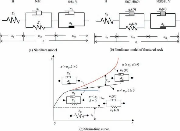
Fig.6.Schematic view and strain–time curve of creep constitutive model.
Here is the constitutive equation of Hook element:
where σ represents the constant stress;andE0the elastic modulus.
In the proposed model,the elements related to the nonlinear growth of creep strain are the damaged viscoelastic and viscoplastic bodies,in which the elastic modulus and viscosity coefficients during the whole creep deformation are no longer constant,but should be variables related to the degradation of rock properties:
whereDis the damage variable;E1the elastic modulus;and viscosity coefficients the η1and η2respectively.
For fractured rock,the initial damage (D1) induced by the preformed crack surface already existed before creep test.Therefore,the total damage (D) of fractured rock simple during creep test should be a coupling damage of the initial macroscopic damage (D1) and the microscopic damage (D2) of rock material induced by external load.Based on the Lemaitre equivalent strain principle,the total damage of fractured rock can be written as [25]
In the laboratory test and macroscopic mechanical analysis,the initial damage (D1) is usually defined as the degradation of elastic modulus [26]:
where the elastic modulus of intact rock and fractured rock are represented byEandFor the microscopic damage(D2),an exponentnegative function is available for defining the degree of damage evolution induced by creep constant load [27,28]:
where the velocity of damage variable change with timetcan be controlled by the parameter α.By plugging Eqs.(5) and (6) into Eq.(4),we obtain the total damage of fractured rock as follows:
Fig.7 shows the evolution process of total damage in fractured rock under different initial damageD1or different parameter α conditions.It can be noticed that the greater the initial damage caused by pre-existing fractures,the higher the cumulative damage of the specimen under the same external load for the same time.The larger the parameter α,the faster the total damage evolution of fractured rock under external loading.According to the results of the elastic modulus from compression test conducted on samples of granite fractured at 30° and 45° angles,the initial damagesD1calculated by Eq.(5) are 0.06 and 0.23 respectively.Then,the constitutive relations of damaged viscoelastic and viscoplastic bodies will be calculated from the expression of total fractured rock damage.

Fig.7.Effect of initial damage and D1 and parameter α on the evolution of total damage.
3.1. The damaged viscoelastic body
The damaged viscoelastic body (N(D)/H(D)) is formed from a damaged Newtonian dashpot and a damaged spring (Fig.6b).The constitutive relation is given by
where εHand εArepresent the strains of the damaged Hook element and damaged Newtonian element;E1(D) and η1(D) the damaged elastic modulus and damaged viscosity coefficient,respectively.
By combining Eq.(3),Eq.(7) with Eq.(8),we obtain the constitutive equation of the damaged viscoelastic body described below:
Appling Laplace transform to the left and right sides of Eq.(9),the following can be obtained:
whereE(s)=L[εve];andsthe transformation parameter.By solving Eq.(10),it can be obtained:
Appling the inverse Laplace transform to Eq.(13),the following expression can be obtained based on the initial condition that εve=0 when timet=0,
3.2. The damaged viscoplastic body
In Fig.6b,we obtain the total stress σ of the damaged viscoplastic body as follows:
In the equation,stresses on the damaged Newtonian dashpot and the plastic element are represented by σdand σprespectively,in which
where σsis the yield limit.
According to the expression of the damaged viscosity coefficient η2(D) in Eq.(3) and the damage equation in Eq.(7),the strain formula of the damaged viscoplastic body is able to be derived:
In the equation,η2is the damaged viscosity coefficient.There is one damaged Newtonian dashpot in the damaged viscoelastic body and another in the damaged viscoplastic body,which are adopted in the new model to reproduce the fractured rock’s steady deformation behavior and accelerated deformation behavior,respectively.Considering that the influences of the damage evolution on the model parameters of η1and η2are not exactly the same,the damage factor β is used in the damaged viscoplastic body in order to differentiate them.
As shown in Fig.6b,the new creep constitutive model of fractured rock gives the total strain as follows:
InEqs.(18a)and(18b),σ andσsrepresenttheapplied stress ofcreep test and the yield stress of material;E0,η1,E1,and η2are the model parameters related to material properties;α and β indicate the damage evolution speeds in the steady and accelerated creep stages.D1is the initial damage of fractured rock,which are 0.06 and 0.23 for granite samples with 30°and 45°inclination fractures,respectively.
3.3. Fractured creep model under triaxial stress state
The expression of total strain εijunder triaxial compression is in the form of tensor:
whereG0means shear modulus;Sijthe deviatoric stress tensor;K0the bulk modulus;σmthe spherical strain tensor;and δijthe Kronecker function.
Under triaxial stress state,Eq.(14)(damaged viscoelastic body)has the expression:
whereG1is the damaged shear modulus;and η1the damaged viscosity coefficient.
For the damaged viscoplastic body,the constitutive relation under three-dimensional stress condition can be shown in Eq.(22).
whereFandF0represent the yield function and its initial value.It is commonly accepted that in the process of creep,the deviatoric stress tensor is very important and we obtain the expression of the yield functionFas follows:
In the equation,parameterJ2means the second deviatoric stress invariant.
Then Eqs.(20),(21) and (22) are substituted for Eq.(19),the following equation which is the fractured creep model under triaxial stress state can be solved:
Considering σ2=σ3in triaxial compressive test,the axial strain of the proposed creep model for fractured rock is able to be derived:
3.4. Sensitivity study
As shown in Eqs.(18)and(25),the creep deformation behavior of fractured rock is associated with many factors.Those parameters are subjected to sensitivity testing in order to better understand their effects.Taking the elastic modulusE1,viscosity coefficient η1and damage parameters α and β as examples,the creep strain response to these parameters can be seen in Fig.8.Substituting σ=140 MPa,σs=128 MPa,D1=0.06,E0=34 GPa,E1=1×10³GPa,η1=1×10³GPa·h,η2=1×10⁵GPa·h,α=0.01 h-1and β=0.2 h-1into Eq.(14b),we can obtain several axial strain–time curves by changing one parameter and keeping the other constant.

Fig.8.Variations of axial strain using different model parameters.
According to the results of numerical calculation,the elastic modulusE1mainly affects the strain progressed to the steady creep stage from transient creep stage.High elastic modulusE1results in lower steady creep strain and lower final creep strain.Variations in creep strain curves due to viscosities (η1) indicate that,the transient-state strain rate and the time transferred to the second stage of creep deformation are highly dependent on η1,however,creep strain rate and final creep strain are not affected by it.For the damage factors α and β,it is apparent that the strain rates in the last two stages of the creep deformation (steady and accelerated stages) are closely related to their values.With the increase of α or β,the damage development process in the steady-state stage or accelerated-state stage becomes more pronounced.A bigger damage factor α or β leads to a higher creep strain rate.
3.5. Discussion in the case of D1=0,α=0 and β=0
When taking no account of the pre-existing damage and effects of damage on the model parameters,the value of the parametersD1,α and β all will be zero.Based on=t,Eqs.(18a),(18b),(25a) and (25b) can be written as:
which exactly are the constitutive expressions of the classical Nishihara model under uniaxial and triaxial compression conditions.That would mean the new proposed creep model of fractured rock is an extension of the Nishihara model.
3.6. Parameter determination for the creep model for fractured rock
To validate the feasibility and rationality of the new creep model for fractured rock proposed in this work,we used the nonlinear creep model of fractured rock to fit and analyze the data from the granite creep test in Section 2.The fitting results are shown in Fig.9a.The experimental data under different test conditions are marked with symbols,and the dashed lines represent the fitting curves of the test data using the nonlinear creep model of fractured rock.The model parameters obtained from the fitting calculation are shown in Tables 2 and 3.In addition,fitting analysis is conducted using both the nonlinear creep model of fractured rocks and Nishihara model for one representative set of test curves.This set includes different inclined angles,different confining pressures,test curves that only exhibit the transient creep and steady-state creep stages,and tests curves that exhibit the whole creep process of transient creep,steady-state creep,and accelerated creep stages.Comparisons between test results and theoretical calculations determined by these two models are presented in Fig.9b–e.
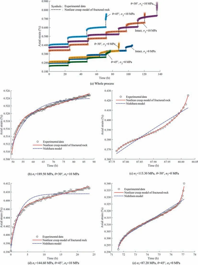
Fig.9.Experimental data of granite samples fitting results by different models.
The fitting results show that the creep test curves of intact and fractured granite under different confining pressures have a high degree of fitting with the newly proposed nonlinear creep model curves,indicating that the model can well describe the creep deformation characteristics of intact and fractured granite and can reflect the three stages of the whole process of creep deformation of granite.In addition,compared with the Nishihara model,the creep model proposed in this paper has significant advantages in describing the creep curves of only transient creep and steadystate creep stages,as well as the creep process curves including transient,steady-state,and accelerated creep stages.The leastsquare fit error of the proposed creep model is significantly lower than that of Nishihara model by almost an order of magnitude.Compared to the situation where the creep rate remained almost constant during the accelerated creep stage described by the Nishihara model,the nonlinear creep model of fractured rock can accurately characterize the sharply increased creep rate and the nonlinear growth of strain during the accelerated creep stage in the experimental process of fractured rocks.
4.Conclusions
A series of creep tests under different axial stresses and confining pressures was conducted to investigate the creep characteristics of intact and fractured granite.An accurate creep model has been developed to capture the full creep progression of fractured rock.The main conclusions are drawn as follows:
(1) The steady creep strain rates present an exponential increase trend with the increase of stress level.Under the same stress conditions,the creep rate of fractured rock is higher than that of intact rock.and the larger the inclination angle,the greater the steady creep strain rate of the specimen.The failure of rock material is the major controlling factor of the failure of 30° inclined fractured granite,while the failure of 45° inclined fractured granite is a coupled failure involving rock material failure and the frictional sliding of the pre-existing fracture.
(2) The initial damage caused by fracture together with damage caused by constant load have been taken into consideration in the proposed nonlinear creep model.The analytical solution of the creep model in three dimensions also has been deduced.The elastic modulusE1in the model mainly affects the strain progressed to the steady creep stage from transient creep stage.The viscosity coefficient η1,the damage factors α and β mainly control the strain rates in the three stages of the creep deformation.
(3) The fitting analysis results indicated that the new proposed model can well describe the creep deformation characteristics of intact and fractured granite and can reflect the three stages of the whole process of creep deformation of granite.The least-square fit error of the nonlinear creep model is significantly lower than that of Nishihara model by almost an order of magnitude.
Nevertheless,the nonlinear creep model proposed is still a preliminary study in the demonstration of the long-term behavior fractured rock.Many aspects of this work,such as the range of the inclination angle of the fracture,and the expression of the damage development during creep process,need to be refined.Further studied on the physical mechanism of the long-term deformation behavior of rock samples with fractures at different inclination angles are still necessary.
Acknowledgements
This work has been supported by the National Natural Science Foundation of China (No.42307258),the technological research projects in Sichuan Province (No.2022YFSY0007),and the China Atomic Energy Authority (CAEA) through the Geological Disposal Program.

- 矿业科学技术学报的其它文章
- Preliminary research and scheme design of deep underground in situ geo-information detection experiment for Geology in Time
- Numerical and experimental investigation on hydraulic-electric rock fragmentation of heterogeneous granite
- Heat transfer and temperature evolution in underground mininginduced overburden fracture and ground fissures:Optimal time window of UAV infrared monitoring
- Classifying rockburst with confidence: A novel conformal prediction approach
- Drilling-based measuring method for the c-φ parameter of rock and its field application
- Pore-pressure and stress-coupled creep behavior in deep coal: Insights from real-time NMR analysis