Investigation of the block toppling evolution of a layered model slope by centrifuge test and discrete element modeling
Leilei Jin ,Hongki Dong ,Fei Ye,* ,Yufeng Wei ,Jinfeng Liu ,Chngkui Wng
a State Key Laboratory of Hydraulic and Mountain River Engineering,College of Water Resource and Hydropower,Sichuan University,Chengdu,610065,China
b State Key Laboratory of Geohazard Prevention and Geoenvironment Protection,Chengdu University of Technology,Chengdu,610059,China
Keywords: Block toppling Centrifuge Anti-dip slope Failure mechanism Discrete element method
ABSTRACT Primary toppling usually occurs in layered rock slopes with large anti-dip angles.In this paper,the block toppling evolution was explored using a large-scale centrifuge system.Each block column in the layered model slope was made of cement mortar.Some artificial cracks perpendicular to the block column were prefabricated.Strain gages,displacement gages,and high-speed camera measurements were employed to monitor the deformation and failure processes of the model slope.The centrifuge test results show that the block toppling evolution can be divided into seven stages,i.e.layer compression,formation of major tensile crack,reverse bending of the block column,closure of major tensile crack,strong bending of the block column,formation of failure zone,and complete failure.Block toppling is characterized by sudden large deformation and occurs in stages.The wedge-shaped cracks in the model incline towards the slope.Experimental observations show that block toppling is mainly caused by bending failure rather than by shear failure.The tensile strength also plays a key factor in the evolution of block toppling.The simulation results from discrete element method (DEM) is in line with the testing results.Tensile stress exists at the backside of rock column during toppling deformation.Stress concentration results in the fragmented rock column and its degree is the most significant at the slope toe.
1.Introductio n
Primary toppling failure usually occurs on rocky slopes with steep anti-dip beddings inclining towards the slope.The primary toppling evolution of slope beddings is mainly attributed to the long-term gravitational stress.However,earthquakes,groundwater,and human activities can promote toppling failure of slope beddings.Goodman and Bray (1976) classified primary toppling failure into three types of flexural toppling,block toppling,and block-flexural toppling based on the mechanical properties of the slope rock mass,the thickness of the rock layer,and the distribution of joints.Generally,theoretical methods(Goodman and Bray,1976;Azarafza et al.,2021),numerical simulations (Zheng et al.,2019a;Azarafza et al.,2020),software development (Zheng et al.,2019b;Ardestani et al.,2021)and laboratory model testing(Adhikary et al.,1997,2007;Ding et al.,2021) are employed to reveal the failure mechanism of primary slope toppling.
The centrifuge modeling test,being a typical laboratory test,has been widely used to study sand liquefaction (Charles et al.,2004),embankment stability (Brandenberg et al.,2005),foundation settlement(Liang et al.,2020),and tunnel safety(Lanzano et al.,2012).A stress field is formed when the centrifugal force produced by the high-speed rotation of a centrifuge acts on the small-scale model.The corresponding stress distribution is close to the gravitational stress field of the actual-scale model.The deformation and failure observed during the centrifuge model testing can interpret some geological phenomena in the field.
The centrifuge modeling test is also currently used to simulate slope failure evolution.Numerous scholars have conducted the centrifuge modeling test for slopes with different soils,such as the saturated sandy soil slope (Taboada-Urtuzuastegui et al.,2002),weakly layered clay slope (Wang et al.,2010),and expansive soil slope (Chen et al.,2017).Based on the results of centrifuge modeling,some scholars have discussed the factors that influence slope stability,such as water level fluctuations (Miao et al.,2018),slope reinforcement (Wang and Zhang,2014),and slope-top loading (Wang and Zhang,2019).
Moreover,the centrifuge modeling test has also been conducted by scholars for rocky slopes.Gypsum is often chosen as a similar material in most centrifuge modeling tests of toppling slopes.Adhikary et al.(1997,2007) carried out centrifuge modeling tests on an anti-dip layered rock model slope made of gypsum,cement and glass fiber,and analyzed toppling failure modes.Zhang et al.(2007) proposed an estimation method for evaluating slope toppling stability,and they validated the method by performing the centrifuge test on the model slope made of gypsum.Li et al.(2015)chose gypsum as the slope material and made an anti-dip model slope containing artificial cracks perpendicular to the beddings.Li et al.(2016) conducted the centrifuge model testing on a steepdip layered carbonate slope and analyzed the slope failure process.Zhang et al.(2020) made the model slope with a mixture of iron powder and gypsum and conducted the centrifuge modeling test to study the failure process of block toppling and the characteristics of the failure surface.
Under the limitation of technical devices,the maximum centrifugal acceleration is relatively small in old centrifuges.Consequently,the soft gypsum is widely adopted to conduct the centrifuge tests.The centrifuge test on the soft gypsum slope cannot fully reflect the evolution characteristics of the rock slope.Until now,few studies regarding to the centrifuge test on hard rock slopes have been reported,and most of the centrifuge modeling tests uses gypsum as the similar material.In this paper,block toppling evolution was explored using a large-scale centrifuge system TLJ-500.This centrifuge system is one of the largest centrifuge systems with a maximum capacity of 500g-t.Since gypsum is a relatively soft material,cement mortar was chosen to make the anti-dip layered model slope in this study.Some artificial cracks perpendicular to the block column were prefabricated.During the centrifuge modeling testing,strain gages,displacement gages,and high-speed camera measurements were employed to record data and images.Then,numerical simulations using discrete element method (DEM) have been carried out to verify the centrifuge test results and analyze the failure mechanism of block toppling.
2.Centrifuge model
2.1.Geotechnical centrifuge
The centrifuge model test was carried out on the TLJ-500 geotechnical centrifuge at Chengdu University of Technology in China,as shown in Fig.1.This geotechnical centrifuge was manufactured by China Academy of Engineering Physics in Mianyang,China.The maximum capacity of the centrifuge is 500g-t.The effective radius of the centrifuge arm is 5 m.

Fig.1.TLJ-500 geotechnical centrifuge used in the testing.
2.2.Materials
Generally,the rock in the block toppling slope is relatively hard.Thus,a relatively-hard similar material is chosen to make the model slope.The corresponding mechanical properties need to be close to the natural rock in the block toppling slope.Accordingly,the similar material should meet the requirements of medium modulus,medium strength,and high density.The similar materials in the model slope are composed of cement,barite powder,and quartz sand.The cement is the cementing material,the barite powder is used to increase material density,and the quartz sand is used to adjust the strength.The mixture proportion of cement,water,quartz and barite is 4:3:4:2 in this work.The physical and mechanical parameters of the similar materials are listed in Table 1.

Table 1Physical and mechanical parameters of the slope block columns used in the centrifuge tests.
2.3.Model installment
The model slope sketch is shown in Fig.2,having a model slope angle of 70°and a 40 mm thickness of each block column,with the slope toe being supported by a wedge-shaped block.The height of the model slope is 743 mm;the lengths of the lower and upper platforms are 415 mm and 350 mm,respectively;and the width of the model slope is 400 mm.The failure mode of the toppling depends on the joint characteristics to a large extent.Steep anti-dip beddings inclining towards the slope are often used as a separation surface of back edge.Gentle inclination joints inclining outward to the slope are often used as a slip surface.According to this situation,we design two groups of discontinuities in the model slope.The first group of discontinuities is a bedding with a dip angle of 70°,inclining towards the slope.The second group of prefabricated discontinuity is perpendicular to the beddings,inclining outward to the slope.The continuity of the second group of discontinuities is 50%.

Fig.2.Sketch and geometry of the model slope (unit: mm) and the locations of the monitoring sensors.
Three displacement gages(W1-W3)were installed at the top of the slope.A total of 24 strain gages(D1-D24)were installed on the slope side.The installation positions of displacement gages and strain gages are shown in Fig.2.
First,the wedge-shaped block made of cement mortar was placed into the model box.After the strength of each block column reached 75% of compressive strength,the block columns were placed in sequence and fixed with cement mortar.The installation of block columns includes three steps (Fig.3a-c).After the installation of the model slope was completed,the tempered glass cover plate was fixed.The deformation and failure of model slope was recorded by high-speed camera through this glass plate.Then,the entire model slope box was weighed.As a result,the required weights loading on the centrifugal arm on the other side was calculated.Finally,the model box was moved to the centrifugal arm and the sensors were fixed (Fig.3d and e).
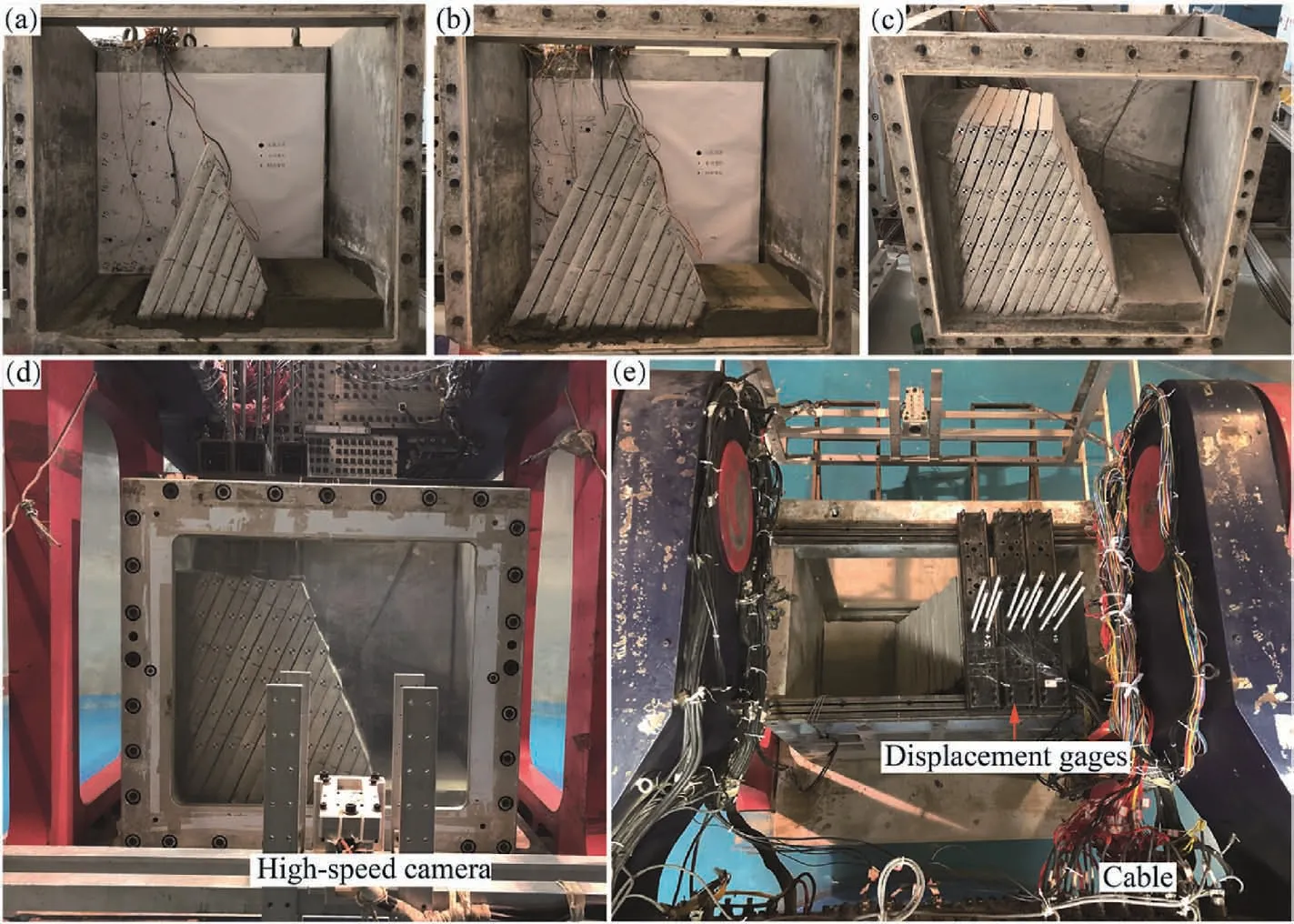
Fig.3.Installment process of the model slope (a-c) and details of the model and the monitoring sensors (d,e).
2.4.Testing procedure
The maximum centrifugal acceleration that acted on the model slope was 120g.The centrifugal acceleration was gradually increased.The acceleration increment was set to 20gfor each load step and the duration of each loading step was 5-10 min.However,when the centrifugal acceleration was increased to 120g,the loading time remained greater than 10 min.The entire procedure of centrifugal acceleration is depicted in Fig.4.Displacement gages,strain gages,and high-speed camera were used to automatically record data and images during centrifuge model testing.

Fig.4.Time points corresponding to typical deformation signs and number of cracks.
The strain gage type is BX120-50AA with a resistance of(120 ± 0.5) Ω,a sensitive grid size of 50 mm × 3 mm(length × width),a substrate size of 55 mm × 5 mm(length×width),a sensitivity factor of 2.06%±1% and a limit strain of 20,000.The displacement sensor is model CW50 with a range of±25 mm,an accuracy of±0.5% of full scale,a supply voltage of 10 V direct current (DC) and an output voltage within ±2 V DC.
3.Results
3.1.Images
Images were recorded by high-speed camera during centrifuge model testing.Comparing the images,the block toppling evolution of the model slope can be divided into seven stages: (I) layer compression,(II) formation of major tensile crack,(III) reverse bending of the block column,(IV)closure of major tensile crack,(V)strong bending of the block column,(VI)formation of failure zone,and (VII) complete failure.The beginning and end times of each stage are marked in Fig.4.The number of cracks on the view-side of model slope was also counted during the centrifuge model testing(Fig.4).Typical images are shown in Fig.5.
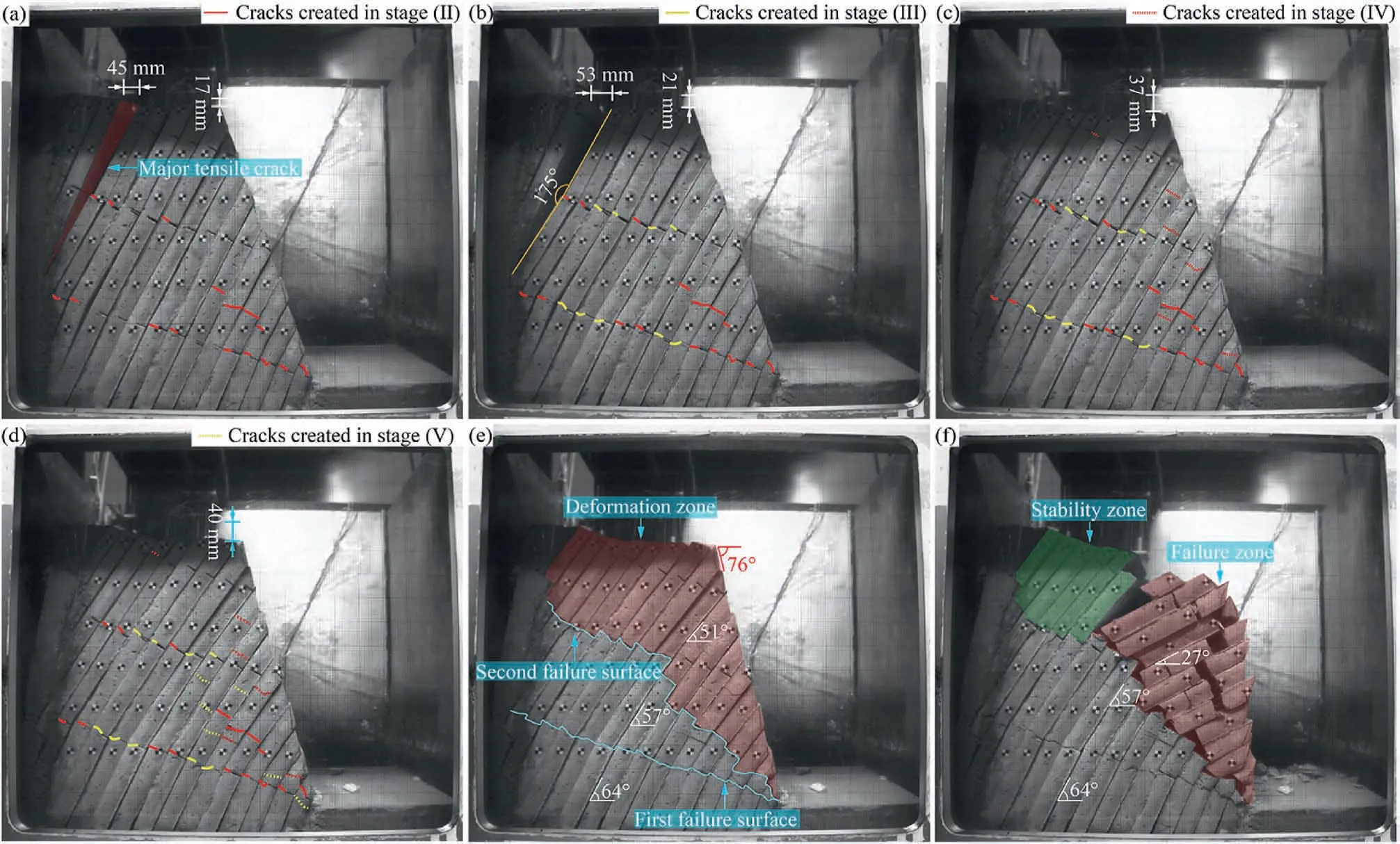
Fig.5.Block toppling evolution in different stages:(a)Formation of major tensile crack,(b)Reverse bending of block column,(c)Closure of major tensile crack,(d)Strong bending of the block column,(e) Formation of failure zone,and (f) Complete failure.
(I) Layer compression
The appearance of the model at this stage is almost consistent with the initial shape before testing.The deformation of the model slope was not significant.This deformation can be attributed to the mutual compression between the block columns.The initial deformation occurred mainly when the centrifugal acceleration increased from 5.7gto 6.47g.
(II) Formation of major tensile crack
The deformation of the block columns at this stage occurred towards the free face direction.The major tensile crack produced by the model slope occurred when the centrifugal acceleration increased from 12.15gto 17.68g.The cracks in the slope appeared first at the slope toe.The continuity of artificial cracks at the deep positions of this stage increased from 50% to 82%.At the end of this stage,the block columns at the back edge separated from each other instantaneously.A major tensile crack with a maximum aperture of 45 mm could be observed,and the major tensile crack was wide at the top and thin at the bottom(Fig.5a).
(III) Reverse bending of the block column
The block columns ahead of the major tensile crack showed significant reverse bending characteristics at this stage.The reverse bending angle reached 5°when the centrifugal acceleration increased to 31.6g(Fig.5b).The reverse bending degree of block columns gradually decreased from the position of major tensile crack to the slope shoulder.The number of cracks on the view-side of model slope reached 26,and the continuity of artificial cracks at the deep positions was approximately 100%.
(IV) Closure of major tensile crack
When the centrifugal acceleration reached 50.34g,the major tensile crack began to close.At the same time,the upper block columns moved further toward the free face due to the complete continuity of the first failure surface at the lower position.The settlement was obvious at the slope shoulder,with a maximum settlement of 37 mm.Of course,the settlement at the slope shoulder led to the closure of the major tensile crack.The number of cracks increased to 31,and these cracks were approximately perpendicular to the block column.Most of the cracks occurred in the shallow positions.In particular,the major tensile crack closed instantaneously when the centrifugal acceleration reached 55.24g(Fig.5c).
(V) Strong bending of the block column
With the increase of centrifugal acceleration,the bending of block columns towards the free face becomes very strong at the slope shoulder.The cracks on the view-side of model slope increased to 37 when the centrifugal acceleration reached 63.32g.Six new cracks were mainly distributed near the slope toe and near the previous cracks.Moreover,the aperture of the cracks increased clearly.This stage lasted until the centrifugal acceleration reached 78.62g.As a result,the total settlement near the slope shoulder reached 40 mm.In particular,a stepped-shape failure surface gradually occurred from the middle part to the slope toe during this stage,which is the second failure surface.
(VI) Formation of failure zone
The anti-dip angles of block columns in the upper,middle and lower parts of the slope model at this stage were significantly different.The anti-dip angles of the block columns are approximately 51°in the upper part,57°in the middle part,and 64°in the lower part.The light red area marked in Fig.5e indicates the formation of the failure zone.Only the failure zone was still undergoing deformation at this stage.
(VII) Complete failure
The microcracks at the slope toe increased significantly when the centrifugal acceleration rose from 88.32gto 100g.The block columns along the second failure surface crushed each other.Finally,the block toppling slope failed under the centrifugal acceleration of 100g.The complete failure zone is marked in Fig.5f.The failure surface included the tensile wedge-shaped cracks,showing the dominance of bending failure in the block toppling failure.
3.2.Displacements
Three differential displacement sensors were installed at the rear section (W1),middle section (W2) and front section (W3) of slope top,respectively.The vertical displacement curves of W1,W2 and W3 are plotted in Fig.6 together with the centrifugal acceleration curve.It is obvious that the displacements did not increase with rising centrifugal acceleration.The W1 sensor at the rear of the slope top only recorded a displacement of 9 mm during the major tensile crack formation stage.The W2 sensor recorded a significant displacement of 90 mm when the major tensile crack was formed,which is over the range.The two sensors W1 and W2 did not record the entire displacement.However,the W3 sensor recorded the entire displacement development.According to the displacement curve of the W3 sensor,the sudden variation of the displacement occurred when the model slope deformed in a short period of time.This phenomenon indicates that the block toppling failure of the slope model is instantaneous.
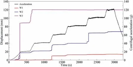
Fig.6.Vertical displacement curves at the slope shoulder monitored by the sensors W1,W2 and W3.
3.3.Strains
Strain gages D1,D3,D8,D9,D15,D17 and D19 are over the range at the major tensile crack formation stage,strain gages D11 and D5 are over the range at the strong bending stage of block column and formation of failure zone stage,respectively,and strain gages D6,D12,D14 and D23 are over the range at the moment of complete failure.The strain curves are shown in Fig.7.Most of the strain gages which are over the range are near the artificial crack.The tensile strength of similar materials is 1.54 MPa and the strain threshold for cracking of the artificial rock is about 1.337 × 10⁻³.Rock column will be fractured once the strain gages are over the range.The failure of the rock is not an accumulation of strain to the fracture threshold,but an instantaneous mutation exceeding the threshold.It is demonstrated that the toppling deformation has a significant suddenness.

Fig.7.Strain curves recorded by strain gages which are over the range:(a)Evolution of strains at the early periods,(b)Evolution of strains at the later periods,(c)Enlarged image of zone I in (a),and (d) Enlarged image of zone II in (b).
The recording data by strain gages which have not exceeded the range are shown in Fig.8.Tensile strain is mostly observed at the backside of the rock column,and in rare cases only compressive strain occurs.The strain data generally increase slowly with test time.There was no direct correlation shown between centrifugal acceleration and strain data,indicating a certain degree of strain hysteresis during toppling.The reason for this is that the rock mass has a large modulus of elasticity.The abrupt changes in the strain data occurred mainly at the beginning and end of each deformation stage.When there is no large deformation in the slope,the strain value is generally less than 2 ×10⁻⁴,and the amount of deformation is small.It can be seen that there is no obvious sign for the toppling before the occurrence of large deformation,which further shows that the failure of toppling is brittle in nature with a significant suddenness.

Fig.8.Strain curves recorded by strain gages which are not over the range.
4.Simulation verification
Numerical simulations using DEM have been carried out to verify the centrifuge test results and analyze the influence of artificial cracks on the toppling failure mechanism.Unlike the centrifuge test,we do not need to increase the acceleration to compensate for the stress loss due to the size reduction while conducting numerical simulation.In the centrifuge test,the model slope failed when the acceleration reached 100g.The size of the numerical model was designed based on the centrifuge model tests at 100g.Thus,the height of the slope model is 74 m,the width at the top is 35 m,and the dip and slope angle are 70°,respectively(Fig.9).
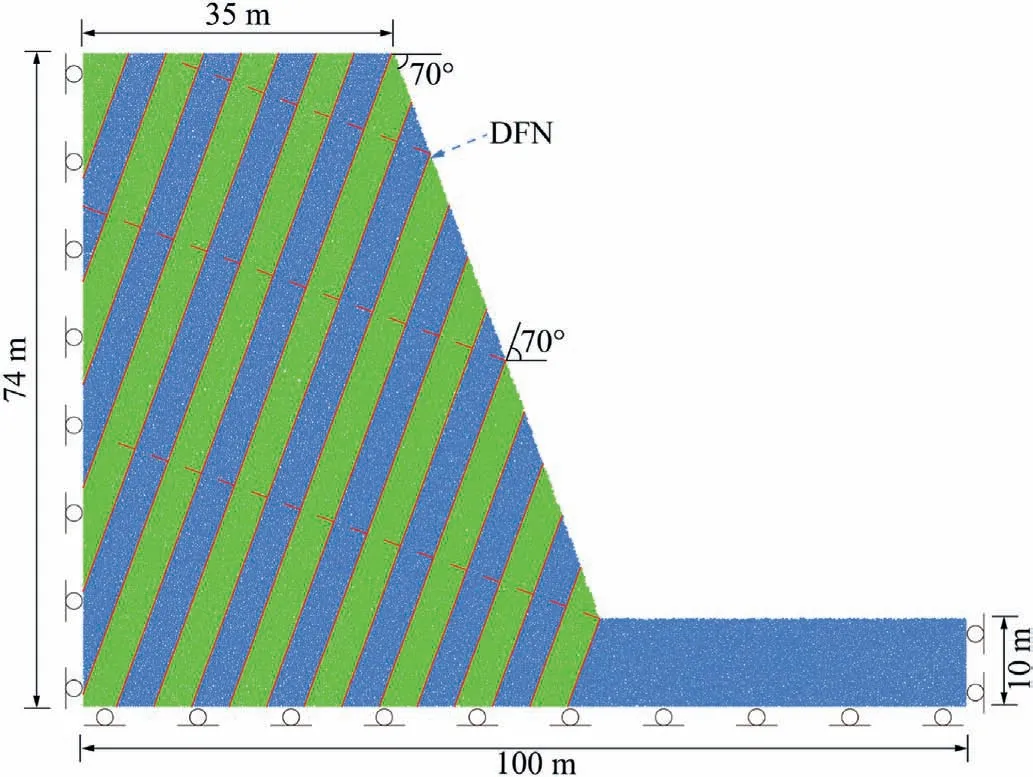
Fig.9.Geometry and boundary conditions of the slope model used in DEM simulation.
The parameters used in the DEM model are determined by the uniaxial compression test results obtained by the numerical simulations and the experimental tests.The comparison between the numerical and experimental uniaxial test results is shown in Fig.10,and the parameters used in the DEM are listed in Table 2.Discrete fracture network (DFN) was used to simulate artificial cracks and layers.Linear contact bond model was used to simulate the rock mass.The vertical and horizontal displacements at the bottom boundary of the model are restricted,and the horizontal displacements at boundaries of both sides are restricted.

Table 2Basic physical and mechanical parameters of the model slope used in the DEM.

Fig.10.Comparison for the uniaxial compression test results obtained by numerical simulation and physical tests.
Fig.11 shows the deformation characteristics and force chains of the slope toppling at 80,000 steps,120,000 steps and 200,000 steps in numerical simulation.The simulation results illustrate that the cracks initially occurred at the slope toe (Fig.11a),gradually developed towards the deep slope along the artificial cracks,and finally formed major tension cracks at the rear of the slope top.After the first failure surfaces fully penetrated(Fig.11b),the second failure surface would develop due to the rupture of the deep and middle artificial cracks.Eventually,the slope failed along the second failure surface (Fig.11c).It can be seen that the main deformation is developed parallelly in the numerical simulation and the model test as a part of proving the reliability of this numerical simulation method and the accuracy of the parameters.

Fig.11.DEM simulation results:Calculation results of deformation at(a)80,000 steps,(b)120,000 steps and (c)200,000 steps;Force chains at(d)80,000 steps,(e)120,000 steps and (f) 200,000 steps.
Numerical simulation by DEM can not only reflect the evolution of toppling deformation,but also illustrate the distribution of force chains within the slope.The force chains within the slope can reflect the magnitude and the transmission pathways of the slope stress at different deformation stages.The numerical results show that the initial force chain is evenly distributed at the initial deformation stage(Fig.11d),and correspondingly the rock column suffered compressive stresses while tensile stresses are mainly distributed at the back of the rock column.The force chains gradually concentrate in the slope(Fig.11d and e),and cause the failure of rock column.The concentration degree of the compressive stress is the most significant at the slope toe,which explained why cracks always occur at the slope toe first.
In addition,numerical simulations have been conducted on the model slope without artificial cracks.Fig.12 shows the results of the numerical simulation without artificial cracks.As shown in Figs.11 and 12,the deformation phenomena of the slopes with or without artificial cracks are quite similar.Deformation initially occurs at the slope toe,following by the graded fractured phenomenon.Fig.13 shows the displacement monitoring results of the two numerical slope models at the slope shoulder.The displacement at the slope shoulder significantly increases after 50,000 steps for the model with artificial cracks,and it significantly increases after 150,000 steps for the model without artificial cracks.The displacement difference between the two models reaches the maximum at 200,000 steps and then gradually decreases.The numerical results show that the artificial cracks in the rock column do not change the failure mode and just hasten the failure process.

Fig.12.DEM simulation results without prefabricated artificial cracks: Calculation results of force chains at (a) 80,000 steps,(b) 120,000 steps,(c) 200,000 steps and (d) 260,000 steps.
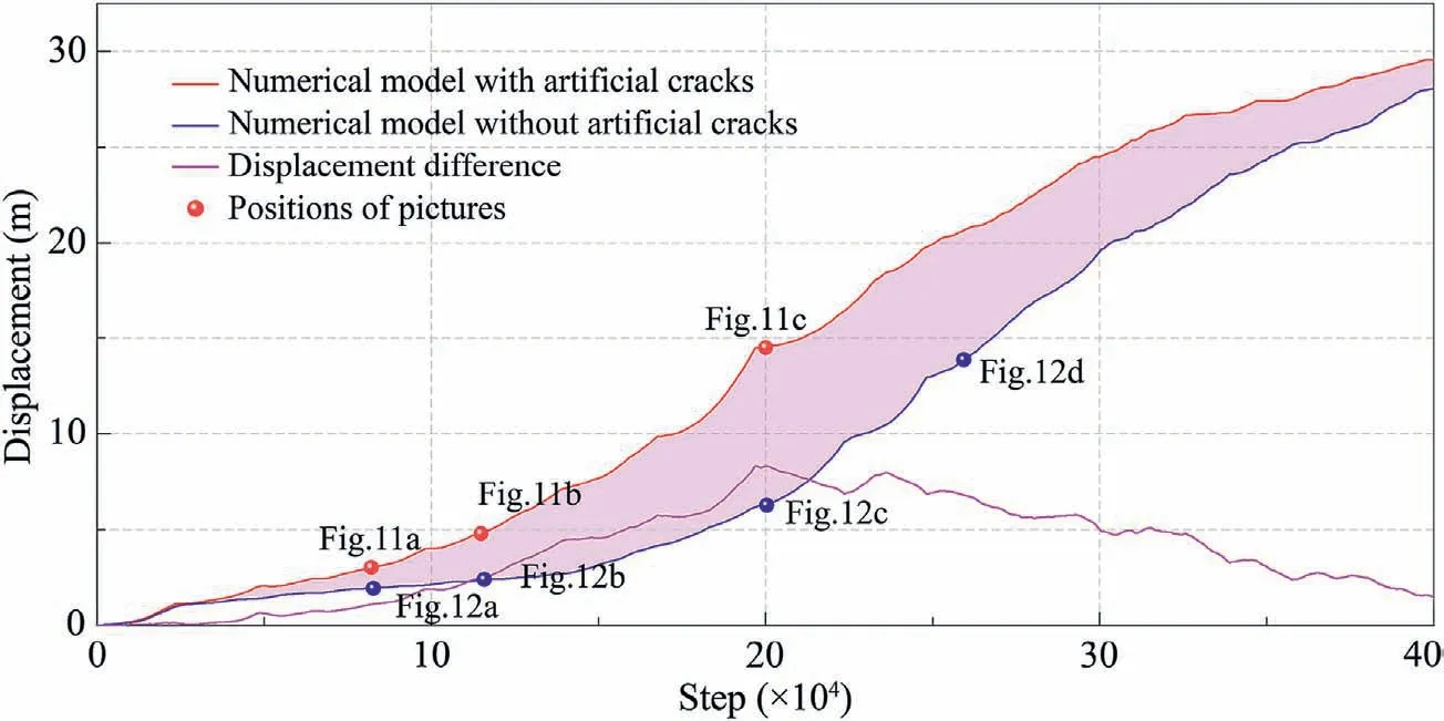
Fig.13.Comparison of slope shoulder displacement results obtained by DEM simulation for the model with and without artificial cracks.
5.Discussion
It is widely accepted by engineering geologists that the antiinclined layered slope is not prone to fail.But toppling failure is widely found in areas around human engineering construction activities,such as hydropower projects,high-speed road and railway projects (Fig.14).The study by Idrees and Pradhan (2018)showed that toppling is the dominant failure type accounting for high-risk rockfall in the cave.Huang and Li (2011) collected 100 cases of large-scale failure slopes in China,and found that one third of them occurred in anti-inclined layered slopes.Cruden (2003)proposed that toppling failure will occur when Eq.(1) is satisfied.

Fig.14.Toppling deformation in engineering practice in China:(a)Toppling occurring at the left bank slope of the eastern gully in Zizhong,China;(b)Toppling occurring at the right bank slope of Lancang River at Wunonglong Hydropower Station;and (c) Toppling occurring at the left bank slope of Lancang River at Wunonglong Hydropower Station.
where β is the slope’s rock dip angle,α is the slope angle,and φ is the internal friction angle of the rock mass.
According to the statistics reported by the literature(Huang and Li,2011)and our investigated landslides,slope angles and rock dips for toppling failure were derived (Fig.15).The probability of slope instability is clearly higher when the sum of the slope angle and twice the dip angle approaches 180°:
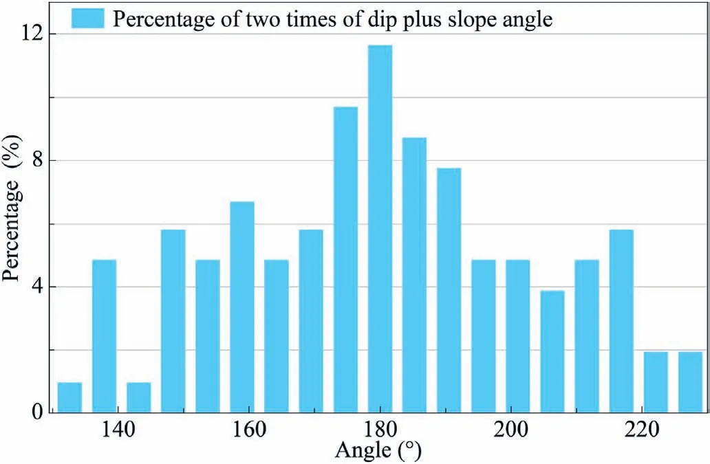
Fig.15.Statistical results for the slope and dip angles of the toppling failure slopes.
In this centrifuge test,the dip angle of the rock above the second failure surface is 51°and the slope angle is 76°before model failure.The sum of 2β and α equals 178°in this slope model,and it satisfies the critical condition of Eq.(2).
Toppling failure is different from sliding failure.The deformation of toppling does not slide along a soft surface,but invert the free face.The toppling failure mechanism of hard rock slopes differs from that of soft rock slopes.Soft rock slopes are more prone to flexural toppling(Fig.14a),while hard rock slopes are more prone to block toppling (Fig.14b),similar to the centrifuge model test in this paper.The process of block toppling deformation can be divided into seven stages,which proves that the deformation occurs in stages.The evolution of the block toppling is characterized by sudden large deformation.The formation and closure of the major tensile crack at the rear of slope top and the failure of the slope all occurred instantaneously.
Photos of the detached model slope after completing the tests are shown in Fig.16.The cracks in Fig.16a-f appeared during the toppling evolution.The cracks along the failure surface are characterized by open edge-shaped cracks towards the slope,which is due to the fact that block toppling is mainly caused by bending failure rather than shear failure.The edge-shaped cracks are caused by the inability of the rock column to bear a large tensile force.In the numerical results,it is clear that tensile stresses are prevalent at the backside of the rock column (Fig.11).In summary,the tensile strength of the column is a key factor in the block toppling.
In engineering practice,a continuous surface is not a sign of block toppling failure.Stable anti-dip slopes with multiple continuous failure surfaces generally exist in the field (Fig.14a).There are two continuous failure surfaces in the evolutionary process of toppling in this test.The first continuous failure surface appears at the reverse bending stage.The dip angle of this surface is small,the surface fluctuates significantly,and the embedding effect of this rough surface restrains the failure of the slope.The second continuous failure surface occurs during the failure zone formation stage,and the slope eventually fails along this surface.
The continuous failure surface occurs at the initial stage with a relatively small dip angle.Although it cannot induce slope failure,it increases the deformation of block toppling.The dip angle of the subsequent continuous failure surfaces gradually increases until block toppling starts.If the second continuous failure surface cannot induce block toppling,the third one will occur.If the third one fails to induce,the fourth one will occur.With the increasing dip angle of the failure surface,the position of the surface is becoming closer to the slope surface.This is how the multi-stage breaking phenomenon occurs (Fig.14).Finally,the sliding instability grows from the surface to the interior of the slope.
At the later stage of the toppling evolution,the block column of the failure surface at the slope toe is strongly broken caused by stress concentration (Fig.16c).The results of numerical tests on force chains reveal this phenomenon of stress concentration visually (Fig.11).Block column of the failure surface with higher elevation is more complete (Fig.16b).This reveals why the slope was still stable when the second failure surface is completely connected.As testing progresses,the slope failed when the rock mass forming the failure surface at the toe fractured.However,none of the existing methods for calculating the stability of toppling takes into account the fact that the failure surface is composed of broken rock masses.In addition,Goodman and Bray(1976)divided the toppling deformation into stable zone,toppling zone and slipping zone.However,the centrifuge test model in this paper only has a toppling zone and a stable zone,and the stable zone is not stabilized by frictional resistance but by the embedding of rock slabs.
6.Conclusions
A large-scale centrifuge system was used to investigate the block toppling evolution of a layered model slope.In the test,strain gages,displacement gages,and high-speed camera measurements were employed to record data and images.Then,numerical simulations using DEM have been carried out to verify the centrifuge test results and analyze the failure mechanism of the block toppling.The following conclusions have been reached:
(1) According to sample statistics,the probability of slope instability is higher when the sum of the slope angle and twice the dip angle approaches 180°.
(2) The centrifuge test summarized seven evolutionary stages of block toppling,i.e.layer compression,formation of major tensile crack,reverse bending of the block column,closure of major tensile crack,strong bending of the block column,formation of failure zone,and complete failure,which proves that toppling deformation occurs in stages.Toppling is characterized by the sudden large deformation.The wedgeshaped cracks inclining towards the slope show that the tensile strength of the rock is a key factor in the block toppling.
(3) The anti-dip rock slope with multiple continuous failure surfaces is usually stable.The failure surface occurs at the initial stage with a relatively small dip angle and a large depth.With the increasing dip angle of the subsequent failure surface,the position of the surface is becoming closer to the slope surface.
(4) The stress concentration gradually occurs at the slope toe,which causes the block column to be broken and eventually leads to the slope failure along the second failure surface.The deformation zone consists of the toppling and stable zones,and the stable zone is not stabilized by frictional resistance but by the embedding of rock slabs.
Declaration of competing interest
The authors declare that they have no known competing financial interests or personal relationships that could have appeared to influence the work reported in this paper.
Acknowledgments
The authors wish to thank National Key R&D Program of China(Grant No.2022YFC308100) and the National Nature Science Foundation of China (Grant Nos.42107172 and 42072303) for financial support.
Appendix A.Supplementary data
Supplementary data to this article can be found online at https://doi.org/10.1016/j.jrmge.2023.02.019.
 Journal of Rock Mechanics and Geotechnical Engineering2024年1期
- Journal of Rock Mechanics and Geotechnical Engineering的其它文章
- Coalbursts in China: Theory,practice and management
- Insights into carbon dioxide sequestration into coal seams through coupled gas flow-adsorption-deformation modelling
- Tensile strength and failure behavior of rock-mortar interfaces:Direct and indirect measurements
- Failure transition of shear-to-dilation band of rock salt under triaxial stresses
- A performance-based hybrid deep learning model for predicting TBM advance rate using Attention-ResNet-LSTM
- Numerical investigation of geostress influence on the grouting reinforcement effectiveness of tunnel surrounding rock mass in fault fracture zones
