High-speed directly modulated distributed feedback laser based on detuned loading and photon–photon resonance effect
Yun-Shan Zhang(张云山), Yi-Fan Xu(徐逸帆), Ji-Lin Zheng(郑吉林), Lian-Yan Li(李连艳),Tao Fang(方涛), and Xiang-Fei Chen(陈向飞),†
1College of Electronic and Optical Engineering&College of Flexible Electronics(Future Technology),Nanjing University of Posts and Telecommunications,Nanjing 210023,China
2College of Communications Engineering,PLA Army Engineering University,Nanjing 210007,China
3College of Engineering and Applied Sciences,Nanjing University,Nanjing 210023,China
Keywords: directly modulated laser(DML),detuned loading effect, photon–photon resonance(PPR)effect,reconstruction-equivalent-chirp(REC)technique
1.Introduction
Because of the explosive development of data communication services such as cloud computing, the data traffic over networks and the demands for large network bandwidth have been increasing rapidly.As the light sources of optical communication systems, high-speed modulated lasers are crucial in solving these problems.Compared with externally modulated lasers like electro-absorption modulator integrated lasers,[1,2]directly modulated lasers(DMLs)have the advantages of cost-effectiveness, small size, low power consumption,and high efficiency.Therefore,it is attractive to improve the modulation bandwidth of DML.
In order to realize high-speed DML, it is essential to increase the relaxation oscillation frequency of the laser.For this purpose,AlGaInAs is usually used instead of InGaAsP in the active region of the DML to obtain high differential gain.[3]Besides, by using buried heterostructure[4,5]and shortening the cavity length of the lasers[6–9]to reduce the volume of the active region,the relaxation oscillation frequency can also be enhanced.However, the buried heterostructure brings about the problem of active region oxidation and increases the manufacturing cost.Moreover,in order to obtain an extremely short cavity length,it is usually necessary to combine various complex processes or structures.Through integrating a distributed feedback(DFB)laser with a passive waveguide[7,8]or passive distributed reflectors,[9]the length of the active region can be reduced beyond the limit of the cleaving process.While the necessary butt-joint regrowth process when fabricating these structures increases fabrication cost and difficulty.
In addition to reducing the active region of the laser,other modulation bandwidth enhancement methods can be used to design high-speed DML.One of them is the detuned loading effect,[10]which is common in conventional distributed Bragg reflector (DBR) lasers.[11,12]When lasing occurs on the long wavelength flank of the DBR mirror, the detuned loading effect can increase the resonance frequency of the laser.[13]The photon–photon resonance(PPR)effect is also widely utilized to improve the bandwidth of DML.[14–16]The interaction between the main mode and an adjacent cavity mode can produce a second resonance peak with a much higher frequency than relaxation oscillation.In a passive feedback laser (PFL),[14]the DFB laser is integrated with a passive feedback section.The PPR effect is generated by injecting current into the feedback section to optimize the phase.The above two effects can coexist in both DBR laser[17]and distributed reflector (DR)laser.[18,19]Therefore, the combination of the two effects can further increase the modulation bandwidth.Similarly, the integration of the active section and the passive section increases the difficulty and cost of chip manufacturing.
In this paper,we propose and demonstrate theoretically a two-section DFB(TS-DFB)laser with sampled Bragg gratings(SBGs).The TS-DFB laser consists of two sections:one plays a role of a general DFB laser,and the other acts as a grating reflector.For simplicity,they are called section I and section II,respectively.Both sections share the same active layer,so the butt-joint regrowth is not required.In order to enhance the modulation bandwidth of the laser, the grating period of the two sections needs to be controlled accurately to achieve the detuned loading effect and PPR effect.The SBGs in the TSDFB laser are used to realize the equivalent change of the period of the seed grating by using the reconstruction-equivalentchirp(REC)technique.[20–22]Consequently,the cost of manufacturing can be greatly reduced.The simulation results show that the direct modulation bandwidth of TS-DFB laser can be improved by 21 GHz or more compared with the conventional one-section DFB(OS-DFB)laser.
2.Principle and model
2.1.Principle of REC technique
In order to improve the characteristics of the DFB lasers, various complicated grating structures (e.g.multiple phase shifts gratings, corrugation-pitch-modulated gratings,and asymmetric gratings)have been developed and used.Yet high-precision control mechanism is indispensable to the fabrication of these sophisticated gratings.Through changing the period or duty cycle of the SBGs,the REC technique can design equivalent subgratings with many complicated structures.Besides,the fabrication of SBGs only needs the conventional holographic exposure and photolithography technology with micrometer-level control accuracy.The principle of the REC technique will be briefly introduced below.[23,24]
Mathematically, the index modulation changes Δn(z) of an SBG can be written as
where,s(z) is a sampling function andΛis the period of the seed grating.Based on the Fourier series expansion,s(z)can be expressed as
whereFmis them-th order Fourier coefficient corresponding to them-th order channel of the SBG, andPis the sampling period of the sampling function.So, equation (1) can be expressed as
It can be obtained from Eq.(3)that the SBG is actually a superposition of many subgratings with different grating periods,and every subgrating has a spectral response corresponding to one of the multiple channels.These periods can be expressed as
From Eq.(4), the channel spacing is determined by the sampling periodP.In actual design,the+1st or-1st subgrating is used as the working resonator.An appropriate sampling periodPshould be selected such that the +1st or-1st channel falls within the gain spectrum of the semiconductor material,while the others are located outside the gain region.As a result, the laser will lase at the wavelength within the +1st or-1st order channel of the SBG.
Now, +1st channel is taken as an example.Based on Eq.(4),the period of seed gratingΛand the sampling periodPsatisfy
whereneffis the effective refractive index,andλis the lasing wavelength.
2.2.Model of the simulation
The time-domain traveling-wave model consists of the time-dependent coupled-wave equations and the carrier rate equation to simulate the lasing characteristics of the proposed TS-DFB laser.[25,26]The electrical field in the waveguide can be described as
whereφ(x,y)is the model function in the waveguide,F(z,t)andR(z,t) represent the forward wave and backward wave propagating in the waveguide respectively,β0is the propagation constant at Bragg frequency, andω0is the reference frequency corresponding to the Bragg wavelengthλ0.The fieldsF(z,t) andR(z,t) satisfy the time-dependent coupledwave equations:
Here,vgis the group velocity.Gandδare the field gain and the detuning factor respectively, andκis the coupling coefficient between forward and backward waves.In this work,we consider only index coupling.ThesF(z,t)andsR(z,t)are the spontaneous emission noise coupled into the forward and backward fields.The noise terms each have a Gaussian distribution and the phase of the noise is assumed to change randomly.
The carrier densityNis described by the time-dependent carrier rate equation as
whereJis the current injection density,eis the electron charge,dis the thickness of the active layer,Ais the linear recombination coefficient,Bis the bimolecular recombination coefficient,Cis the Auger recombination coefficient,gis the gain coefficient,N0is the transparency carrier density,εis the gain compression factor,andSis the photon density which is related to the magnitude of the propagating wave amplitudes as
The field gainGin Eqs.(7a)and(7b)is expressed as
whereΓis the confinement factor of the active layer, andαis the waveguide loss caused by free electron scattering and absorption.
The detuning factorδin Eqs.(7a)and(7b)represents the deviation from the Bragg condition due to the change of the refractive index in the waveguide and can be defined as
whereneff0is the effective refractive index at transparency,Δnis the change of the refractive index and can be written as
whereαHis the linewidth enhancement factor.
Ifz=0 at the facet on the left-hand side, the boundary condition for the forward and backward propagating wave at the facet satisfies
whererlandrrare the amplitude of the reflectivity at the facets on the left-and the right-hand sides,respectively,φlandφrare the phase at the facets on the left-and the right-hand sides,andLis the laser cavity length.
In this work, we focus on the DFB lasers fabricated by REC technology.Hence, the grating in the simulation is a sampled grating.In the part without change of the refractive index, we set the coupling coefficientκ=0.According to Eq.(5),it satisfies in our simulation that
whereP1is the sampling period of section I and can be calculated from the Bragg wavelengthλ0and the period of seed gratingΛthrough Eq.(14).
For section II,only the sampling period instead of the period of the seed gratingΛneeds to be changed,thereby reducing the difficulty of fabrication.
3.Design principle and simulation results
3.1.Design of TS-DFB laser
The proposed structure of the TS-DFB laser is shown in Fig.1(a).It consists of two sections separated by electrical isolation.Therefore, two regions can be independently injected by different currentsI1andI2.Section I works as a general DFB laser, and the other serves as a detuned grating reflector.Moreover, the two sections share the same active layer,so the butt-joint regrowth process is avoidable.The facet of section I is high-reflection (HR) coated and the facet of section II is anti-reflection(AR)coated.The light is output after passing through the grating reflector.The reflectivity of the HR coating is set to 0.92.Figure 1(b)shows the grating structure fabricated by the REC technique in the two sections.The SBGs in the two sections have the identical coupling coefficientκand seed grating periodΛ.The only difference is that the gratings of the two sections have distinct sampling periods,denoted asP1andP2respectively.In the simulation,the equivalent normalized coupling coefficient of the SBGs is set to 1,where the duty cycle of the sampled gratings is considered.The duty cycle of the SBGs is 0.5.Other parameters used in the simulation are given in Table 1.
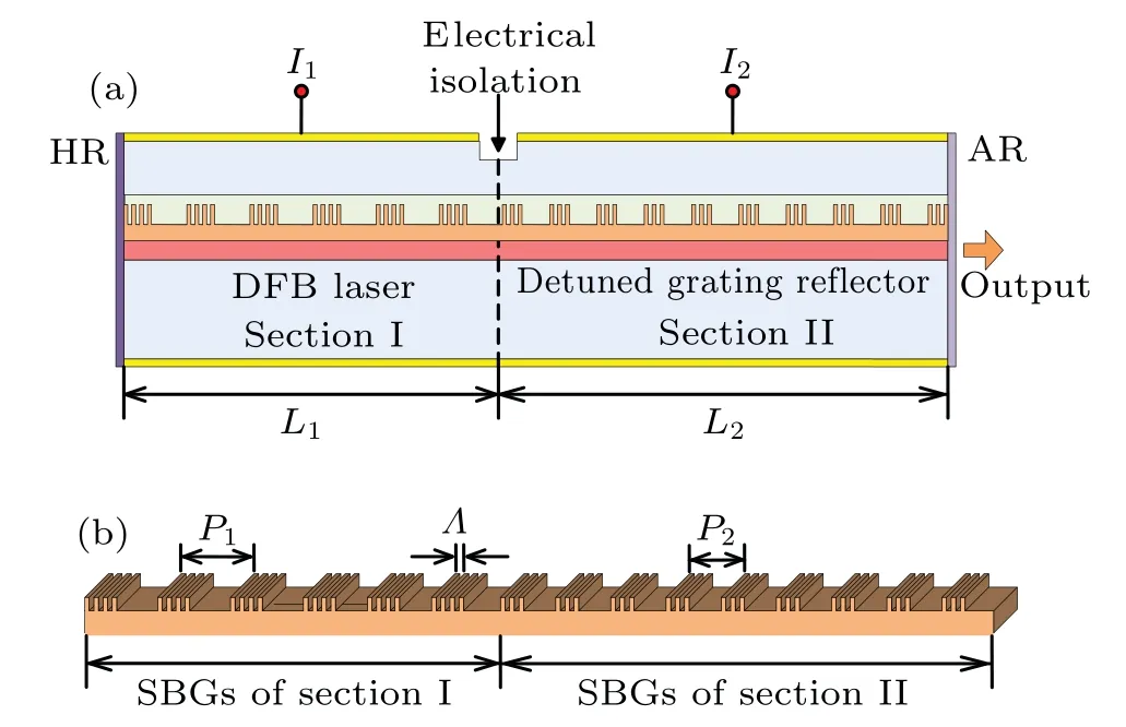
Fig.1.Schematic diagram of(a)proposed TS-DFB laser and(b)grating structure of the TS-DFB laser.
In order to make better use of the detuned loading and the PPR effects to enhance the modulation bandwidth of the TS-DFB laser, the SBGs in the two sections need different sampling periods,that is,detuning between the grating Bragg wavelengths in the two sections is realized.Figure 2 shows the reflection spectrum of the grating reflector and the round trip phase of the laser,which are calculated by the transfer matrix method[27,28]after the effective refractive index and gain distribution in the laser cavity have been obtained from the timedomain traveling-wave model.The detuning of the gratings can make the main mode fall on the long wavelength flank of the reflection spectrum.Under modulation,the frequency upchirp of the TS-DFB laser shifts the main mode to the Bragg peak of section II.The longitudinal confinement factor is increased.As a result, the detuned loading effect can increase the resonance frequency.[11]Moreover, the side mode which is close to the main mode can resonantly amplify the modulation sidebands.Thus,PPR effect can further improve the 3-dB bandwidth.
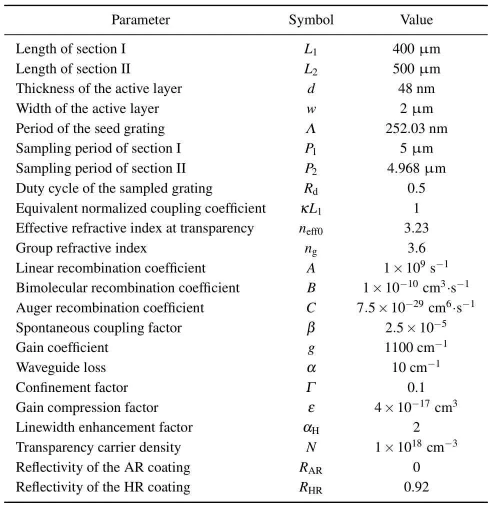
Table 1.Parameters used in simulations.

Fig.2.Reflection spectrum of detuned grating reflector and round trip phase of the laser,with the positions of the modes in profiles represented by circles.
3.2.Static characteristics of the TS-DFB laser
Figure 3(a)shows the longitudinal photon density distribution of the TS-DFB laser when the injection currentI1is 100 mA.Since the light of the TS-DFB laser is output from the grating reflector side, the photon density will be reduced due to the absorption loss and reflection, implying a lower output power.The bias currentI2can be added to the reflector section to compensate for the loss and increase the output.Thus, the photon density at the output facet of the TS-DFB laser will become higher.The light–current characteristics of the TS-DFB laser are shown in Fig.3(b).It can be seen that the bias currentI2has a great influence on the light–current characteristics of the TS-DFB laser.WhenI2increases, the threshold current decreases and the slope efficiency increases.The threshold currents of the TS-DFB laser are about 22 mA forI2=0 mA and 9 mA forI2=10 mA,and correspondingly the slope efficiencies are about 0.248 mW/mA and 0.277 mW/mA.

Fig.3.(a)Calculated photon density distribution of TS-DFB laser with injection current of 100 mA and(b)light–current characteristics of TSDFB laser for I2=0 mA and 10 mA.
The spectrum of the TS-DFB laser is shown in Fig.4,which is calculated based on the model proposed in Ref.[29].The side mode suppression ratio(SMSR)is 42 dB.Moreover,it can be seen that there is a side mode at about 0.2 nm off the main mode, which is named PPR mode.The PPR mode can improve the modulation bandwidth effectively, which is consistent with the laser design in Fig.2.

Fig.4.Lasing spectrum of TS-DFB laser,with injection current being 100 mA.
3.3.Dynamic characteristics of TS-DFB laser
To calculate the small-signal modulation response of the TS-DFB laser, a small sinusoidal current is added to the bias current of section I.Figure 5 shows the response curves of the TS-DFB laser with different detunings of the grating Bragg wavelengths in the two sections.It is obvious that the detuning between the SBGs in the two sections has a significant influence on the modulation bandwidth of the TS-DFB laser.The larger detuning can make the main mode fall on the steeper Bragg wavelength flank of section II, which can enhance the detuned loading effect.Therefore,the resonance frequency is improved.Moreover, it can generate and strengthen the PPR mode, so that the PPR effect can better generate a resonance frequency at high frequency.
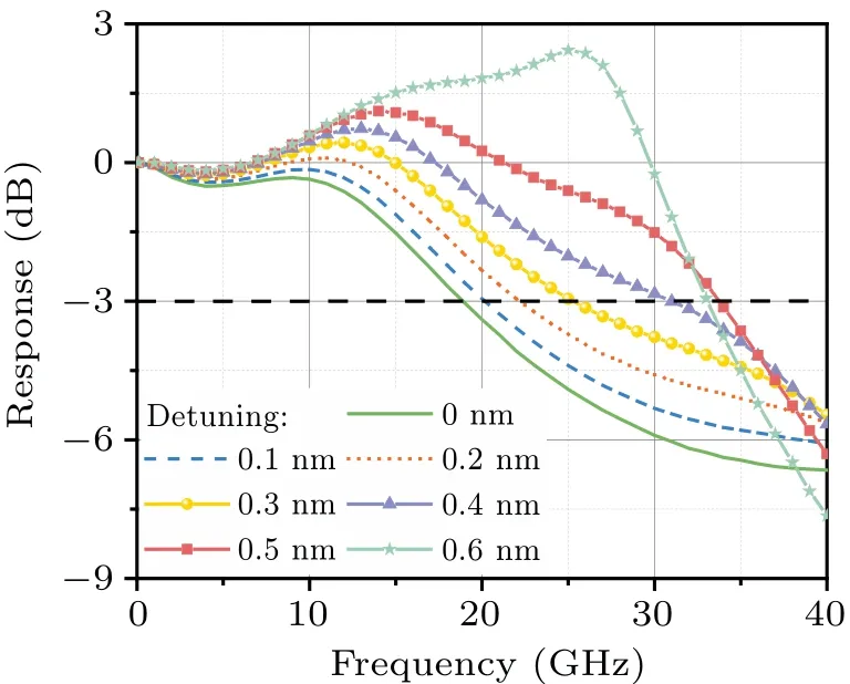
Fig.5.Response curves of TS-DFB laser with different detunings between SBGs in the two sections,with I1 being 100 mA.
The small-signal response curves of the TS-DFB laser with different values of injection currentI2are shown in Fig.6(a).For comparison, the response of the conventional OS-DFB laser with a cavity length of 400 μm is also given.The 3-dB modulation bandwidth of the OS-DFB laser is only about 16 GHz.However,for the TS-DFB laser,it can be seen that the detuned loading effect enhances the resonance frequency,and the PPR effect forms a second resonance peak on the response curve.The modulation bandwidth increases from 34 GHz to 37 GHz whenI2is tuned from 0 mA to 15 mA.The increase of the reflection of the grating reflector enhances the resonance strength of the PPR peak.WhenI2is 20 mA, the mode hops from the long wavelength flank of the Bragg peak to the short wavelength flank as shown in Fig.6(b).This is because with the increase ofI2, the effective index of section II decreases,and the reflection spectrum moves towards the short wavelength.In this situation,the detuned loading effect is absent.The mode spacing is too large, so the PPR effect does not work.Therefore, the modulation bandwidth is attenuated to 15.5 GHz.Hence, a current large than 20 mA only makes the effective refractive index smaller and cannot improve the direct modulation bandwidth.
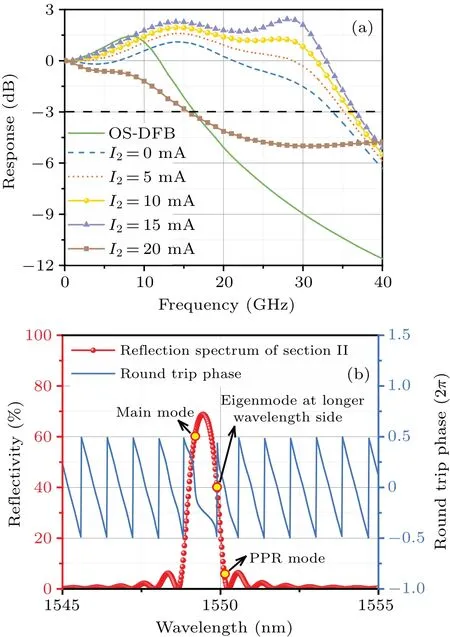
Fig.6.(a) Response curves of TS-DFB laser, with I1 being 100 mA and injection current I2 having different values, and (b) reflection spectrum of grating reflector and round trip phase of the laser,with I2 being 20 mA.

Fig.7.Response curves of TS-DFB laser with different lengths of section II,with I1 being 100 mA and I2 being 10 mA.
The influence of the grating reflector length on the modulation response is illustrated in Fig.7.
The separation between the main mode and the PPR mode is determined by the cavity length of grating reflector.The longer the grating reflector,the closer the PPR mode is to the main mode,and the overlap between the two resonance peaks becomes more and more.As shown in Fig.7,when the cavity length of section II is 600 μm,the PPR mode is very close to the main mode,and the second resonance is very strong.When the length of section II is 400 μm,the spacing of the PPR mode from the main mode becomes larger,so the second resonance peak is at a higher frequency.However,the resonance strength is weaker,due to the weaker feedback of the shorter grating reflector.When the length is further reduced, the PPR mode is too far away and too weak to increase the modulation bandwidth.Therefore,the length of the grating reflector should be appropriately designed to maximize the enhancement of the modulation bandwidth brought by the PPR effect.
In the above calculations,the random phase of the grating at the HR facet was set to 0.However, in practice, the phase randomness of the grating is uncontrollable.Therefore, facet phaseφis changed to study its effect on the high-speed modulation characteristics.Figure 8(a)shows the response curves of the TS-DFB laser whenφis varied from 0 to 0.8π.It can be seen that under certain phase conditions,mode hopping occurs and the modulation bandwidth is attenuated.Whenφis 0.6π,the 3-dB bandwidth is only 21 GHz.In order to study the effect of the random phase on mode hopping, the normalized threshold gain margin between the eigenmode at the shorter wavelength side and the lasing mode is calculated,and the results are shown in Fig.8(b).It can be seen that when the random phase is 0, the normalized threshold gain margin is less than 0.25.Therefore, when the current of the reflection section is too large,mode hopping occurs as shown in Fig.6.The normalized threshold gain margin is 0 when the random phase is changed from 0.7πto 0.9π,which means that the lasing occurs at the eigenmode on the shorter wavelength side.Thus,the small-signal modulation response deteriorates.

Fig.8.(a) Response curves of TS-DFB laser with different values of facet phase φ with I1 being 100 mA and I2 being 15 mA.(b)Normalized threshold gain margin between the main mode and the eigenmode on the shorter wavelength side versus facet phase φ.
Figure 9(a)shows the lasing spectrum whenφis 0.6π.It can be seen that the main mode lases within the stopband due to the random phase of the grating.As a result, the spacing between the main mode and the PPR mode becomes larger.As can be seen from Fig.9(b), the PPR frequency, in this case,is about 65 GHz,which is about 55 GHz larger than the first resonance peak.Because the two resonance peaks are too far apart, the response curve is attenuated below 3 dB before reaching the second resonance peak.Therefore,the PPR effect cannot improve the modulation bandwidth effectively.By increasing the currentI2,the loss of the grating reflector section is compensated for and the reflectivity is increased.Then the resonance strength of the PPR peak is enhanced,which counteracts the roll-off of the response.Consequently, the modulation bandwidth can reach around 73 GHz.Obviously,there are two PPR peaks in the response curves.The reason is that the multi-mode rate equation is used in the simulation,another resonance peak is caused by another side mode.

Fig.9.(a) Lasing spectrum of TS-DFB laser, with φ being 0.6π.(b)Response curves of TS-DFB laser with I2 having different values, I1 being 100 mA,and φ being 0.6π.
In order to better demonstrate the high-speed characteristics of the TS-DFB laser,the eye diagrams under direct modulation are calculated and compared.Figure 10 shows the eye diagrams of the TS-DFB laser and the OS-DFB laser under 25-Gb/s,40-Gb/s,and 55-Gb/s direct modulations.The lasers are biased at 100 mA and the modulation amplitude is 20 mA.The optimal bandwidth condition of the TS-DFB laser is selected,and the random phase of the grating is 0.It can be seen that the eye diagrams of the TS-DFB lasers have larger opening extent than those of the OS-DFB laser.Under 25-Gb/s direct modulation,the clear eye-openings of two kinds of DFB lasers can be obtained owing to the enough modulation bandwidths.Obviously, the OS-DFB laser cannot meet the higher modulation rates.In contrast, the TS-DFB laser can achieve clear eye-openings and large mask margins under all three modulation rates.These results are consistent with the calculations of their modulation bandwidth in Fig.6.

Fig.10.Eye diagrams under direct modulation at 25 Gb/s,40 Gb/s,and 55 Gb/s by(a)conventional OS-DFB laser and(b)TS-DFB laser.
4.Conclusions
A directly modulated two-section DFB laser with sampled gratings is proposed and investigated theoretically.Since the two sections share the same active layer and the gratings are fabricated by the REC technique, the difficulty in manufacturing the lasers is greatly reduced.High-speed DML is realized by exploiting the detuned loading, and PPR effects.Compared with the OS-DFB laser,the TS-DFB laser has large direct modulation bandwidth.Therefore, the proposed laser can be used as a light source for high-speed optical communication systems.
Acknowledgements
Project supported by the National Key Research and Development Program of China(Grant No.2020YFB2205804),the National Natural Science Foundation of China (Grant Nos.61974165 and Grant 61975075), and the National Natural Science Foundation of China for the Youth,China(Grant No.62004105).
- Chinese Physics B的其它文章
- Dynamic responses of an energy harvesting system based on piezoelectric and electromagnetic mechanisms under colored noise
- Intervention against information diffusion in static and temporal coupling networks
- Turing pattern selection for a plant–wrack model with cross-diffusion
- Quantum correlation enhanced bound of the information exclusion principle
- Floquet dynamical quantum phase transitions in transverse XY spin chains under periodic kickings
- Generalized uncertainty principle from long-range kernel effects:The case of the Hawking black hole temperature

