The dynamic response of a high-density polyethylene slow-release structure under launching overload
Ke-Bin Zhang,Wen-Bin Li,Yu Zheng,Wen-Jin Yao,Chang-Fang Zhao
School of Mechanical Engineering,Nanjing University of Science and Technology,Nanjing,210094,China
Keywords:Artillery ammunition HDPE Finite element analysis Slow-release structure Threaded connection
ABSTRACT Based on the 60 mm artillery grenade,a slow-release structure was designed to reduce the severity of ammunitions response to accidental thermal stimulation and improve the thermal stability of ammunitions.The slow-release structure was made of high-density polyethylene (HDPE) and connected the fuse and the projectile body through internal and external threads.To study the safety of the slowrelease structure under artillery launching overload,mechanical analysis of the slow-release structure was simulated via finite element analysis(FEA).The impacts of various factors(e.g.,fuse mass,number of threads,and nominal diameter of internal threads of the slow-release structure) on the connection strength of the slow-release structure were studied.A strength-prediction model based on the fuse mass and internal thread parameters was established by fitting the maximum effective stress of the slowrelease structure.This led to good prediction results.In conclusion,this study provides references and theoretical support for the design of thermal protection structures insensitive to ammunition.
1.Introduction
Ammunition charges can accidently ignite under external heat:This leads to ammunition malfunctions and can cause severe damage to personnel and the launching platform [1-3].Thermal mitigation technologies can control the reaction evolution of energetic materials in the presence of external heat,thus reducing the ammunition response level.Thermal mitigation is a key technology in the design of insensitive ammunition [4-6].Artillery ammunition is often fired by artillery,which offers a high muzzle velocity,low cost,and small dispersion [7].However,the ammunition will be subjected to a large overload during the launching process,which makes it difficult to design the slow-release structures.Thus,it is critical to study thermal mitigation technologies in artillery ammunition.
To improve the thermal stability of the ammunition,significant research has been conducted on the slow-release structure of projectiles.Liang et al.[8,9]introduced a shape memory alloy wire cutting device for rocket engines.The required shape memory was first implanted into the memory alloy during machining,and the memory alloy wire was then wound outside the rocket engine.When the rocket engine is in a high temperature environment that may cause propellant reaction,the shape memory effect of memory alloy acts to cut the rocket engine shell,relieve pressure and slow down the reaction of energetic materials in the shell.
Madsen et al.[10]designed a liner with a low melting point.that the liner encapsulates the explosive within the projectile and melts when the explosive begins to burn,thus providing an escape path for the explosive combustion products.The BLU-109 warhead used by the U.S.military [11,12]adopted a tail-exhaust structure.The original tail structure utilized a low melting point metal to fix the tailgate of the projectile body.The metal melts when the ammunition is subjected to thermal stimulation,and the tailgate loses its fixation.The tailgate falls off under the action of a spring,thus exposing the internal explosive and leading to pressure relief.
The BLU-122 warhead from the U.S.military[11,12]used a head pressure relief method.The sealing plug on the head is fixed by a low melting point material.When the ammunition is subjected to external thermal stimulation,the material melts,and the sealing plug is expelled due to internal pressure,thus achieving pressure relief.The head and tail of the U.S.military’s MK-146 rocket [13]include exhaust structures made of polymer materials that had successfully passed the cook off and shooting tests.Chen et al.[14]designed a polyethylene slow-release structure based on the balance between the pressure growth rate caused by the decomposition as well as combustion of explosives in the projectile versus the pressure release rate of the exhaust.Cook-off tests showed that the slow-release structure could significantly reduce the response level of the warhead to thermal stimulation.Shen et al.[15]designed a slow-release structure by changing the strength of the threaded connection between the casing and the end cap,and obtained the matching relationship between the charge area of a certain HMXbased aluminum-containing explosive and the area of the pressure relief hole.Dai et al.[16,17]created holes in the bottom tail cap of a large penetrator and filled it with a low melting point material,which significantly reduced the reaction level of the penetrator under slow cook off conditions.Xu et al.[18]designed the polyethylene slow-release structure for composition B warhead and studied the response characteristics of composition B warhead under the condition of slow cook-off.The test results show that when the pressure relief hole area is 2.5% of the charge area,the response grade of composition B warhead is combustion.Xu et al.[19]also studied the influence of polyethylene slow-release structure on the cook-off characteristics of FOX-7 explosive fuze.The test results show that under the conditions of slow cook-off and fast cook-off,the slow-release structure can effectively reduce the internal pressure of the fuze at the response time and reduce the response level of the fuze under the cook-off conditions.These studies are mainly focused on the design of slow-release structures for ammunition with a low overload.There are few studies on the design of slow-release structures for artillery ammunition.
Chen et al.[20]used a custom-made device to study the reaction characteristics of four types of low-melting-point materials (polyethylene (PE),polybutylene terephthalate (PBT),nylon PA6,and polycarbonate PC) under the individual and coupled effects of temperature and pressure.The results showed that PE was more likely to form exhaust channels at explosive reaction temperatures than other materials.The melting point of high-density polyethylene(HDPE) is around 130°C.It has a relatively high strength among polyethylene materials and is low density,non-toxic,and with good impact resistance.Thus,HDPE is an excellent material for ammunition slow-release structures.
Thus,this work used low-melting point HDPE to design a slowrelease structure for a 60-mm artillery grenade.The stress process of the slow-release structure under the launching overload were simulated using LS-DYNA software.The effects of the fuse mass,the number of threads of the slow-release structure,and the nominal diameter of the internal thread on the connection strength of the slow-release structure were thus investigated.A strength prediction model based on the fuse mass and internal thread parameters was established by fitting the maximum effective stress of the slow-release structure.Finally,the relationship between the parameters of the slow-release structure and projectile-related parameters of the 60-mm artillery grenade under launching conditions was determined.
2.Design of the slow-release structure
The projectile moves along the barrel during launching and is subject to combined action of the pressure on the bottom,the pressure of the belt,the lateral force of the guide,the friction between the belt and the rifling,the pressure of the filling,and the inertial force.If the strength of the projectile does not meet the requirements,then the projectile will disintegrate in the barrel,thus resulting in unpredictable damages[21,22].During launching,the stress on the projectile head is small [23],and the velocity of fragments generated by the head after explosion is small [24].To ensure launching safety and sufficient projectile detonation power,a slow-release structure was designed in the connection between the 60-mm projectile body and the fuse(Fig.1).The projectile mass was 2.8 kg,and the fuse mass was 0.35 kg.Table 1 shows the basic parameters of the slow-release structure.

Table 1Basic parameters of the slow-release structure.

Fig.1.Structure diagram of the 60-mm projectile.
The slow-release structure was made of HDPE,which is essentially a ring with both internal and external threads.During the projectile-assembly process,the fuse and the projectile body were connected via the internal and external threads of the slow-release structure.When the projectile was subjected to accidental thermal stimulation,the HDPE melts such that the fuse and the projectile body are separated,thus forming an exhaust channel to relieve the high pressure.
When the projectile travels in the barrel,the pressure of the propellant accelerates its movement.At this point,the fuse maintains its original position due to the inertial force,and it makes contact with the top of the projectile body.The slow-release structure bears almost no load as shown in Fig.2(a).When the projectile exits the muzzle,the propellant pressure decreases rapidly,and the sudden unloading generates a tensile wave inside the projectile [25].This tensile wave causes the fuse and the projectile body to separate,and the internal and external threads of the slow-release structure are subjected to forces in opposite directions-these forces constrain the movement of the fuse(Fig.2(b)).
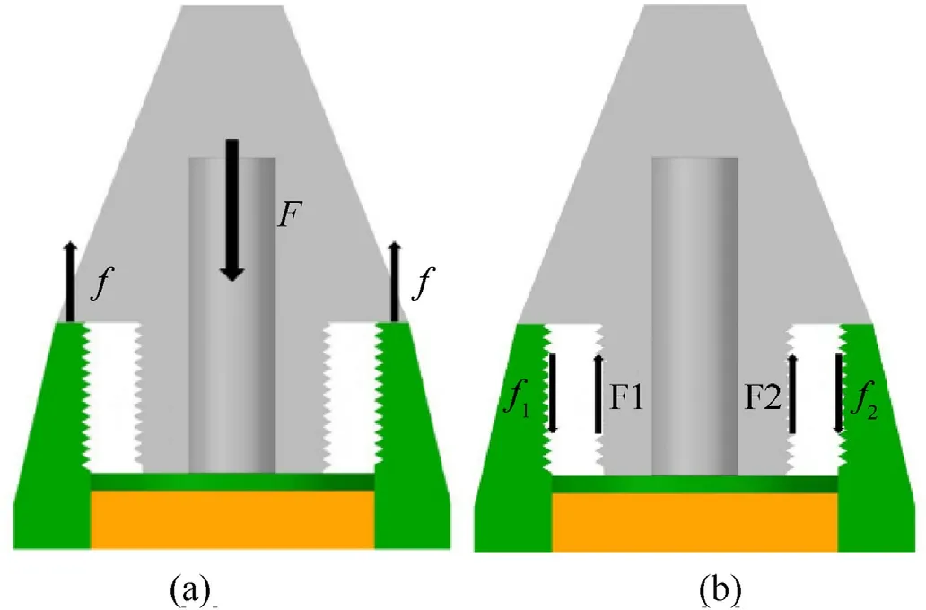
Fig.2.Mechanical analysis of the slow-release structure: (a) The fuse and the projectile body are pressed against each other;(b) The fuse and the projectile body are separated from each other.
3.Dynamic response analysis of the slow-release structure under launching overload
The movement of the projectile during launching is complex,and it is challenging to obtain the effect of the tensile wave on the slow-release structure through theoretical analysis.It is also difficult to directly measure the dynamic response of the projectile components through physical experiments.Here,a finite element model of the projectile was established using HyperMesh software,and the impact of the fuse mass and the parameters of the slowrelease structure on the connection strength of the slow-release structure under launching overload were then studied with LSDYNA software.
The stress conditions of the slow-release structure during launch used the following assumptions for the factors that have little influence on the analysis [23,25,26]:
(1) The acceleration stage of the projectile in the barrel is very short(usually on the millisecond level),and we assumed that the high-speed impact extrusion process of the projectile is adiabatic.
(2) During launching,the impact of projectile rotation on the projectile strength is small.Thus,the influence of rotation on the slow-release structure is ignored.Specifically,the tangential inertial force and the guiding-side force generated by projectile rotation are ignored.
(3) The initial stress and gravity of projectile components are negligible.
(4) The hindering effect of the front shock wave(the compressed air column formed due to the higher velocity of the projectile than the speed of the air in front of the projectile) on the projectile when the projectile moves in the barrel is negligible.
(5) For convenience of finite element modeling,features such as chamfer,fillet,protrusion of the centre part,obturator ring,and the undercut of the fuse thread are ignored.
(6) This study mainly focused on the strength of the slowrelease structure when the projectile exits the muzzle.The friction between the projectile and the barrel and the extrusion process of the projectile belt are ignored.The projectile belt is simplified to be a part of the projectile body.
(7) The propellant gas pressure on the projectile is simplified to be a uniform load on the bottom of the projectile.To study the influence of the tensile wave on the slow-release structure when the projectile exits the muzzle,we assumed that the propellant pressure drops to zero instantly after the projectile exits the muzzle.
3.1.Finite element model
3.1.1.Finite element model of the threaded part
The slow-release structure is a threaded component.The projectile body and the fuse that connects with the slow-release structure are also threaded.Many scholars have done a lot of research on the finite element modeling of threads.Chen et al.[27,28]established a simplified two-dimensional axisymmetric bolted connection model.Although it can simulate the load transfer,it is too simplified and has a big gap with the actual situation.Jiang et al.[29]established a simplified three-dimensional symmetrical thread annular groove model,simplified the thread spiral into several parallel annular grooves,and considered load transfer and stress concentration,but ignored the thread spiral effect and could not obtain accurate analysis results.He et al.[30]proposed an accurate and practical method to build a thread finite element model,and the simulation results of the model are in good agreement with the experimental results.Here,a finite element model was created according to He et al.[30]using the profile of the thread.Fig.3(a) shows the profile of the external thread,which is divided into three segments in the vertical direction: A-B (root),B-C(flank),and C-M(crest).Based on the mathematical expression(1) of the external thread profile,the cross-section of the external thread in the plane perpendicular to the thread axis is obtained(Fig.3(b)).The cross-sections of the threads perpendicular to the thread axis have a constant shape and rotates around on the thread axis.

Fig.3.Thread profile:(a)Vertical cross-sectional profile of the external thread;(b)Cross-sectional profile of the external thread perpendicular to the thread axis;(c)Cross-sectional profile of the internal thread in the vertical direction,and (d) cross-sectional profile of the internal thread perpendicular to the thread axis.
The profile of the internal thread is shown in Fig.3(c).Through the mathematical expression Eq.(2) of the profile of the internal thread in the three segments,the cross-section of the internal thread in the plane perpendicular to the thread axis is obtained(Fig.3(d)).
To obtain a high-quality hexahedral meshing for the threads,the bottom-up modeling method was used in HyperMesh14.0.Taking the slow-release structure as an example,the thickness of one pitch of the internal and external threads of the slow-release structure was equally divided into 30 layers along thePaxis;the thicknesses of each layer wasP/30.The profiles of adjacent cross-sections are of the same shape with a rotation angle of 12°.First,the 2D elements of the threads of the slow-release structure were established as shown in Fig.4(a).To convert the 2D elements into 3D solid elements,the 2D section was divided into 30 equal parts along the circumference.Then,30 copies of the 2D elements were obtained through rotation and translation,and 3D solid elements were created by mapping.Fig.4(b) shows the solid elements of a single section of the internal and external threads.The threads of the slow-release structure in this study were right-handed,and there were 15 threads.Thus,the finite element model of the slow-release structure was established by translating and duplicating 15 singlesection threads as shown in Fig.4(c).

Fig.4.Finite element model of the slow-release structure:(a)2D element;(b)3D solid element of single-section thread,and(c)finite element model of the slow-release structure.
3.1.2.Finite element model of the projectile
The threads of the fuse and the projectile body were also modelled according to the above steps.Fig.5 shows the finite element model of each component of the projectile.The model in this study were meshed with high-quality hexahedral elements.The axial element size of the threaded part was 0.05 mm,and the maximum element size of other parts of the projectile was set to 6 mm.This study mainly focuses on the connection strength of the slow-release structure.In order to ensure the accuracy of finite element simulation,this study has carried out grid independence verification,and the results are shown in Table 5.The results show that the grid size used in the calculation is reasonable.Fig.5(d)shows the finite element model after the projectile is assembled.The contact type between various components was set toAutomatic Surface to Surface.The F-F cross-section show that the threads of the fuse,the slow-release structure,and the projectile body had a good fit.

Fig.5.Finite element model of each part of the projectile: (a) Fuse;(b) Explosive;(c)Projectile body,and (d) projectile assembly drawing.
3.2.Material properties
In ANSYS/LS-DYNA,solid 164 was selected for the element type of each part of the projectile.The elastoplastic hardening model(*MAT_PLASTIC_KINEMATIC) was used for the fuse and the projectile body.The linear elastic model (*MAT_ELASTIC) has continuous,uniform,and isotropic properties and was used for explosives with relatively small deformations and simple loads.Table 2 shows the material properties of each part of the projectile.

Table 2Material properties of each part of the projectile[25].
The material used for the slow-release structure was HDPE.The constitutive model(*MAT_PLASTICITY_POLYMER)was adopted;its accuracy was verified previously[31].The simulation parameters of the slow-release structure are shown in Table 3 and Table 4 [31].The constantsCandPin Table 4 are determined by experiments.

Table 3Material properties of HDPE[31].

Table 4Parameters of the constitutive equation of HDPE [31].
3.3.Numerical simulation of projectile launch
The primary load of the projectile during launching is the gas pressure of the propellant.The internal ballistic calculation method of Ye et al.[23]was used to obtain the pressure-time (P-t) curve during launching of a projectile with a mass of 2.8 kg using a 60-mm smoothbore cannon (loaded with 0.3 kg 4/7 propellant and 0.7 kg 15/19 propellant)as shown in Fig.6.The pressure reached a maximum of 232.5 MPa at 3200 μs,and the pressure at the time of projectile exiting the muzzle(8309 μs)was 55.74 MPa.According to the previous assumption,the pressure dropped to 0 MPa after the projectile exits the muzzle (8310 μs).
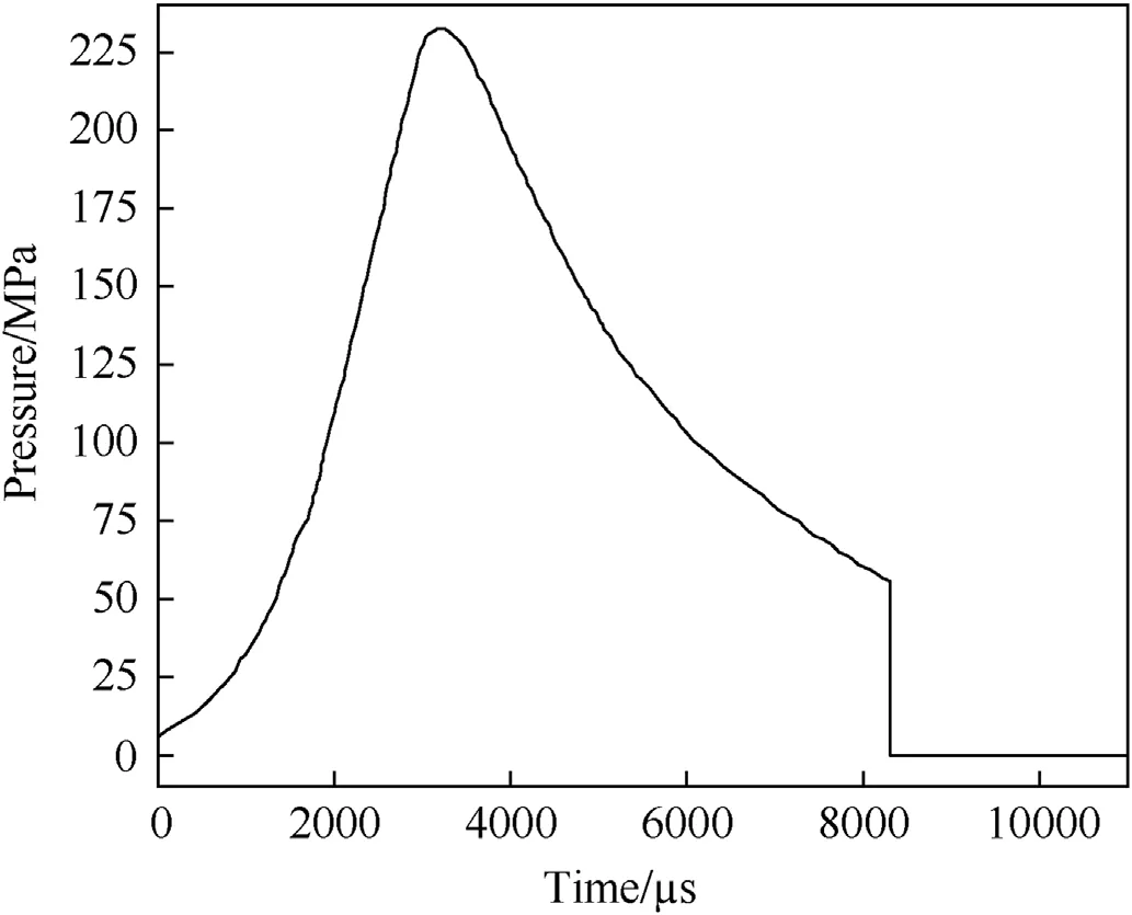
Fig.6.Propellant gas pressure during 0-11000 μs.
The obturator ring was ignored in this model because the lower surface of the obturator ring could fail due to excessive deformation.That is,the force on the lower surface of the obturator ring was ignored,and only the uniformly distributed propellant pressure was applied at the bottom of the projectile.
Table 5 shows the numerical simulation results of different element sizes of the slow-release structure.The results show that the element size of the slow-release structure is reasonable.

Table 5Grid independence verification.
3.3.1.Kinematics of the projectile parts
Fig.7 shows velocity-time curves of the projectile component in the barrel.The velocity of the projectile was 952.05 m/s when exiting the muzzle.After the projectile exited the muzzle at 8310 μs,the fuse and the projectile body experienced velocity fluctuations due to the rapid decrease in the propellant pressure after the exit.The relative motion of the fuse and the projectile body is constraint by the slow-release structure,and thus the velocities of the projectile body and the fuse eventually became the same.

Fig.7.Velocity-time curve of each part of the projectile.
Fig.8 shows a tensile stress map in the axial direction of the projectile.There was no tensile wave inside the projectile from 0 to 8309 μs.A tensile wave appeared in the projectile after 8309 μs due to the rapid decrease of the propellant pressure.This wave propagated from the bottom of the projectile body and reached a contact surface between the projectile body and the fuse at 8336 μs.As the tensile wave reached the fuse,there was a large velocity difference between the fuse and the projectile body (Fig.7).From 8336 μs to 11000 μs,the tensile wave was continuously transmitted,thus causing relative motion of the fuse and the projectile body.The tensile wave gradually disappeared after 10000 μs.The velocities of the projectile body and the fuse eventually became the same(Fig.7).

Fig.8.Stress map of the projectile in the axial direction.
Fig.9 shows the relative displacement of the fuse and the projectile body in the axial direction of the projectile.There was relative motion between the projectile body and the fuse when the projectile exited the muzzle.There was obvious relative motion at 8336 μs,and it reached a maximum of 0.0915 mm at 8382 μs.Fig.8 and Fig.9 show that there was vibration between the projectile body and the fuse after 8336 μs,and the tensile wave gradually dissipated,thus causing the relative displacement to decrease.
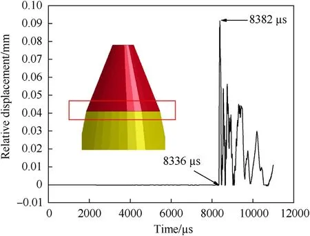
Fig.9.Relative displacement between the fuse and the projectile body in the axial direction.
3.3.2.Dynamic response of the slow-release structure
To ensure a reliable connection between the projectile body and the fuse,it became necessary to study the dynamic response of the slow-release structure during projectile launch.Fig.10 shows the effective stress map of the slow-release structure from 0 to 8309 μs.The simulation results showed that before the projectile exited the muzzle,the stress was mainly concentrated in the external threads of the slow-release structure with a large amount of stress at the root.The force on the slow-release structure was very small because the fuse was in contact with the end surface of the projectile body mouth.The maximum stress did not exceed 10 MPa,which is lower than the static yield strength of HDPE.Fig.9 and Fig.10 show that the stress of the slow-release structure gradually increased with increasing propellant gas pressure.The effective stress was symmetrically distributed in a semi-elliptical shape in the axial cross-section.The stress of the slow-release structure gradually decreased once the propellant gas pressure was reduced.The stress was due to elastic deformation of the part of the fuse that was in contact with the projectile body.
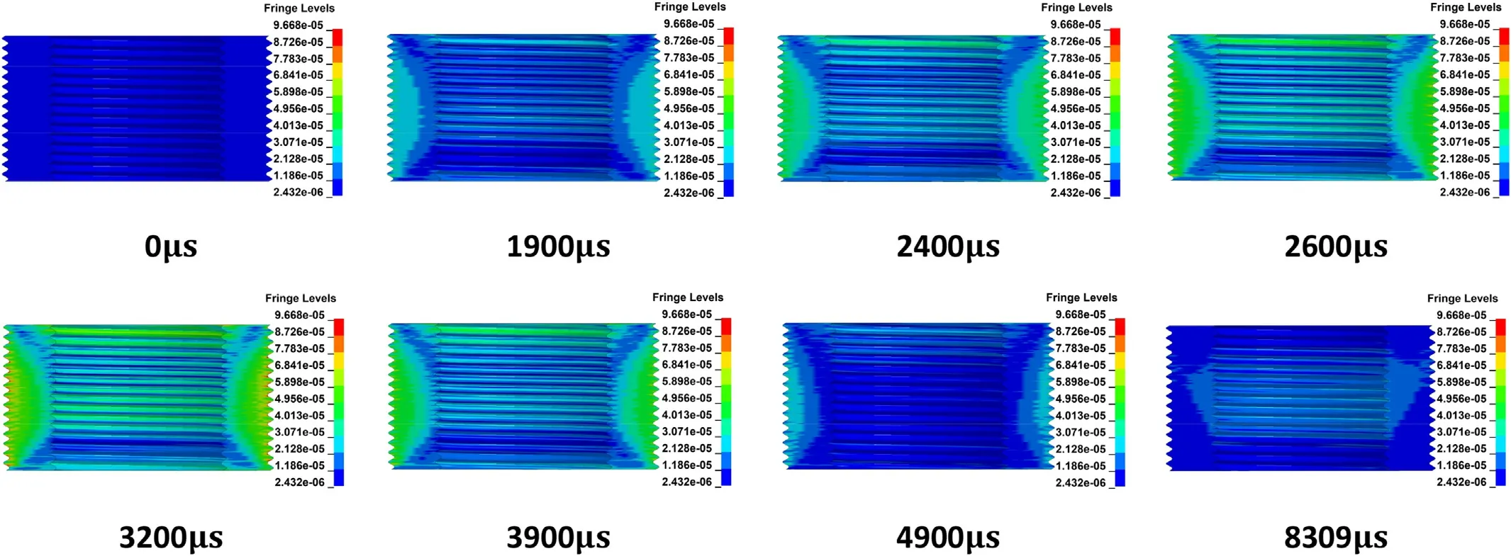
Fig.10.Effective stress of the slow-release structure from 0 to 8309 μs.
Fig.11 shows the effective stress of the slow-release structure after the propellant gas pressure dropped to zero.Fig.8,Fig.9,and Fig.11 indicate that the tensile wave was not transmitted to the fuse after the projectile exited the muzzle(8310-8336 μs).The relative displacement between the fuse and the projectile body was small,thus resulting in little stress of the slow-release structure.At 8340 μs,stress began to increase on the lowermost thread of the inner threads of the slow-release structure and on both sides of the axial cross-section.The fuse was connected with the internal threads of the slow-release structure,and the threads of the slow-release structure were subjected to squeezing and shearing from the fuse.The stress of the slow-release structure gradually increased from 8340 μs to 8382 μs,and the stress area expanded upward from the bottom thread of the internal threads and reached a maximum at 8382 μs.From 8382 μs to 8446 μs,the fuse moved towards the projectile body under the constraint of the slow-release structure,and the stress of the slow-release structure gradually decreased.Displacement between the fuse and the projectile body increased and then decreased from 8446-8506 μs due to repeated transmission of the tensile wave in the projectile.The stress of the slowrelease structure first increased and then decreased.The stress of the slow-release structure gradually disappeared after 10000 μs.
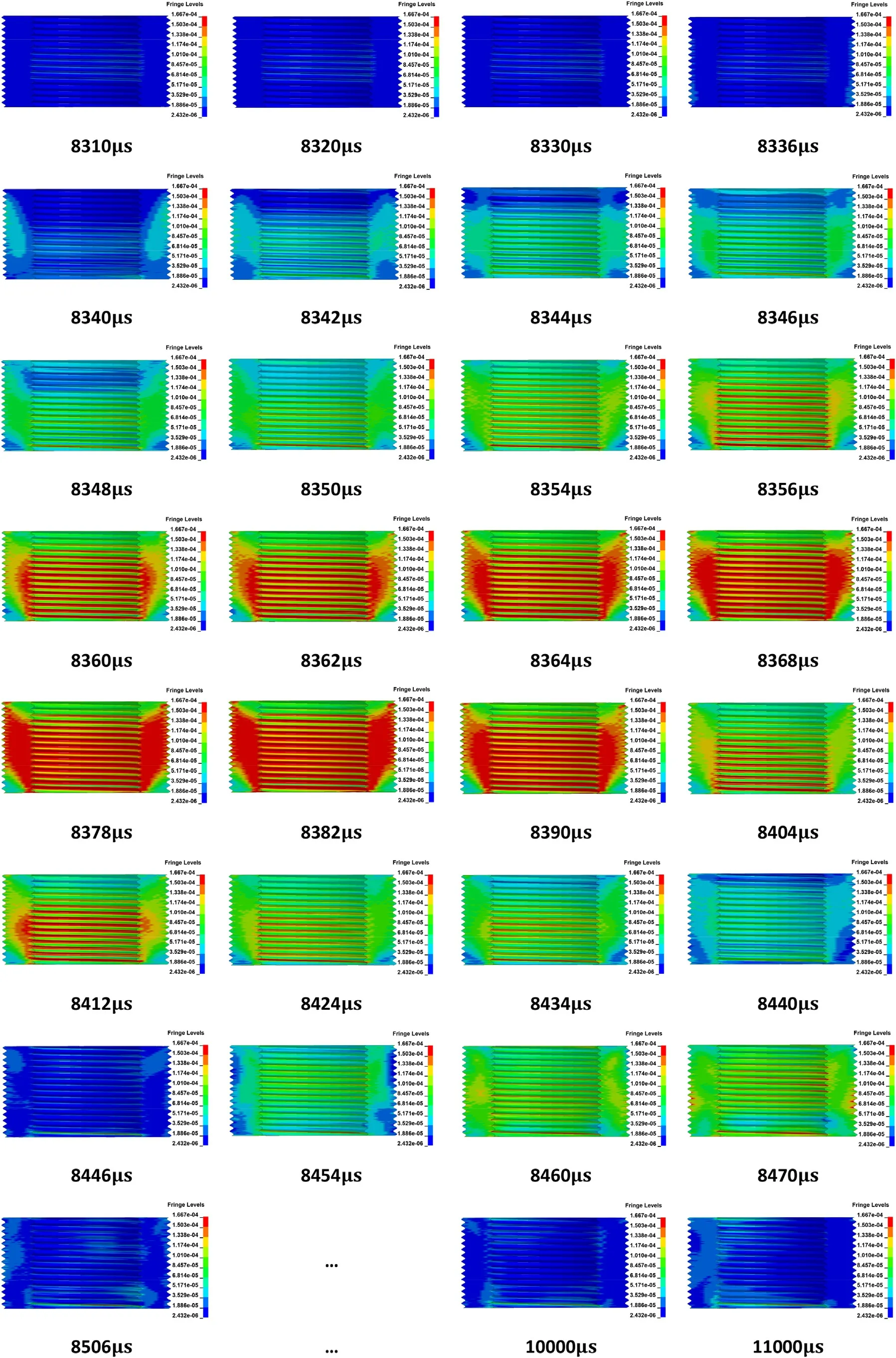
Fig.11.Effective stress of the slow-release structure from 8310 to 11000 μs.
To analyse the dynamic response of the slow-release structure during the projectile launching process,16 observation points(Fig.12)were selected in the internal and external thread root area,and the corresponding effective stress and strain curves are shown in Fig.13.

Fig.12.Observation points on the slow-release structure: (a) Observation point on the internal thread and (b) observation point on the external thread.

Fig.13.Effective stress and effective strain curve of the observation points on the slow-release structure: (a) Effective stress of the observation point on the internal thread;(b)Effective stress of the observation point on the external thread;(c)Effective strain of the observation point on the internal thread,and(d)effective strain of the observation point on the external thread.
Fig.13(a)and Fig.13(b)show that the stress of the internal and external thread from 0-8309 μs had a similar trend with propellant gas pressure.The stress at the external thread was generally greater than the internal thread.From 0-8309 μs,the stress of elements 389857-278354 on the external thread first increased and then decreased from bottom to top;the maximum stress was 10 MPa.The maximum stress of the internal thread elements was 4.52 MPa.
Fig.13(a)shows that the stress of the internal threads began to increase rapidly after 8330 μs,and the stress of the observation points (element: 393326-281002) gradually decreased from bottom to top.The maximum stress was found at the root of the lowermost thread: 38.35 MPa.The stress of the internal thread gradually decreased with increasing time.After 10000 μs,the stress of the element 393326 fluctuated near 8 MPa,and the stress of other elements basically decreased to zero.Fig.13(b)shows that the stress of the external threads began to increase rapidly after 8334 μs;the maximum stress was 17.6 MPa.The stress of the external threads gradually decreased with longer time,and the stress of the elements basically dropped below 2.5 MPa after 10000 μs.Fig.13(c)and Fig.13(d) show that the maximum strain of the slow-release structure during launching occurred in the lowermost internal thread(0.018).
The analysis above suggested that it is important to focus on the strength of the lowermost thread of the internal thread when evaluating the reliability of the slow-release structure during the projectile launching process.The strain rate of the slow-release structure reached 103s-1,and the yield stress of HDPE at a strain rate of 935 s-1was 44 MPa[31]and the safety factor was selected as 1.1.This led to the allowable stress of HDPE: [σ]=40 MPa.The maximum element effective stress of the slow-release structure did not exceed the dynamic allowable stress of HDPE,and the deformation was small.Thus,the strength of the slow-release structure with the tested parameters met the requirement for projectile launching when the projectile mass is 2.8 kg,and the fuse mass is 0.35 kg.
3.4.Factors affecting the connection strength of the slow-release structure
In projectile design,the total mass of projectiles is generally kept constant to match with existing artillery.However,the different types of projectile charge and different charges of mass lead to different requirements on the diameter of the pressure relief hole on the slow-release structure.Moreover,the mass of the projectile connected to the slow-release structure also changes.Therefore,it is necessary to study the impact of the mass of the connecting part with the slow-release structure and the dimensional parameters of the slow-release structure on the connection strength.
3.4.1.Influence of the mass of the connecting part of the slowrelease structure
The masses of the explosive and the fuse were changed to investigate the influence of the mass of the connecting part on the connection strength of the slow-release structure.The specific parameters are shown in Table 6.The projectile model was simulated using the same parameters and projectile loading conditions as above.

Table 6Mass of each part of the projectile.
Fig.14 shows the stress of the lowermost thread of the slowrelease structure in projectiles #1 to #4.The stress of the slowrelease structure during projectile launching and after exiting the muzzle increased to varying degrees with the increasing fuse mass.Moreover,there was large stress fluctuation of the slow-release structure after the projectile exited the muzzle due to increased fuse mass.Fig.15 shows the maximum effective stress of the slowrelease structure.The simulation results suggest that the maximum effective stress increased with fuse mass ratiom/m*(m*=0.35 kg)in a nonlinear way.
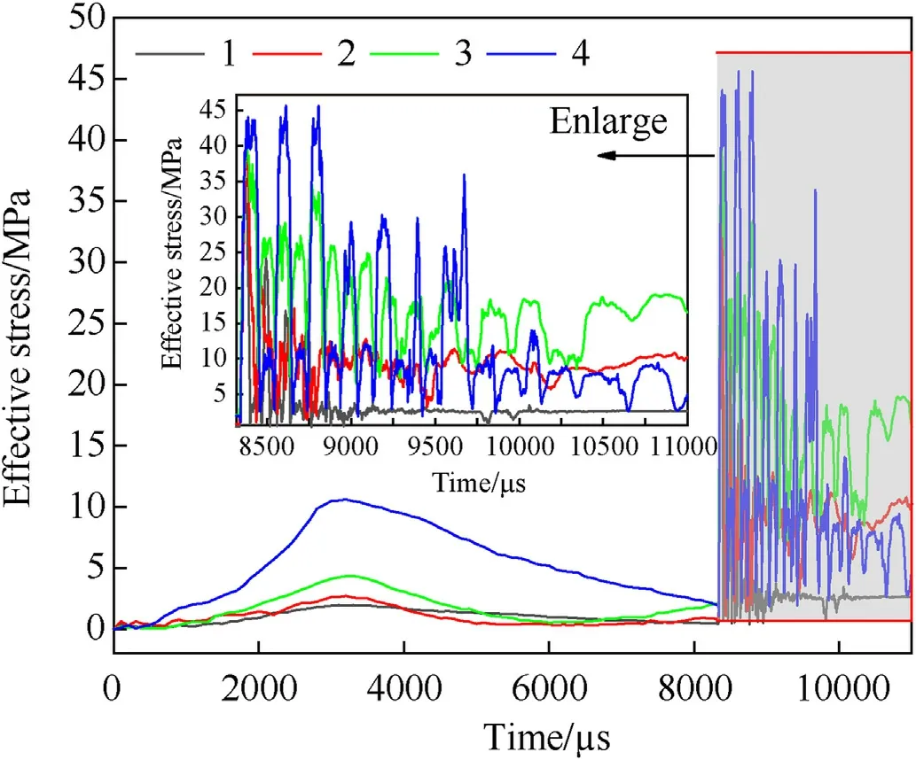
Fig.14.Stress of the lowermost thread of the slow-release structure in projectiles #1 to #4.

Fig.15.Maximum effective stress of the slow-release structure with different fuse masses.
3.4.2.Influence of dimensional parameters of the slow-release structure
Previous analysis showed that the internal threads of the slowrelease structure was subjected to relatively large overload during the projectile launching process (including the short flight period after exiting the muzzle).Therefore,different finite element models of the slow-release structure were established to study the influence of the internal thread parameters on the strength of the slowrelease structure.The specific parameters of the slow-release structure are shown in Table 7.To ensure the tightness of the projectile,the pitch range is very small,and thus,the influence of pitch variation on the connection strength was not studied.Finite element simulation of the projectile model was performed using the same projectile (0.35 kg fuse and 2.45 kg projectile body and charge) and loading conditions.

Table 7Parameters of the slow-release structure.
3.4.2.1.Nominal diameter of internal threads.Fig.16 shows the stress of the lowermost thread of the slow-release structure in projectiles #2 and #6a-#6c.The stress of the slow-release structure after the projectile exited the muzzle decreased with increasing nominal diameter of the internal threads;the stress fluctuation and time for stress reduction both decreased.Fig.17 shows the maximum effective stress of the slow-release structure.The results showed that the maximum effective stress increased with increasing nominal diameter ratio of the internal threadD*/D(D*=27.2 mm) in a non-linear way.
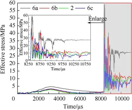
Fig.16.Stress of the lowermost thread of the slow-release structure with different nominal diameters of internal threads.
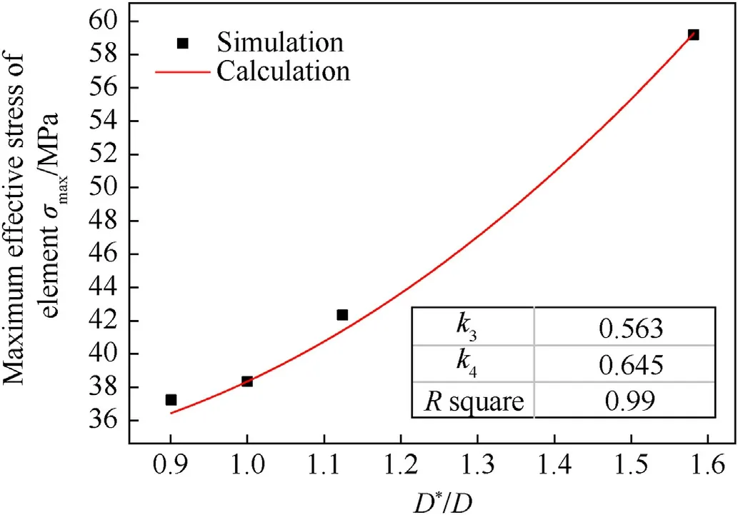
Fig.17.Maximum effective stress of the slow-release structure with different nominal diameters of internal threads.
3.4.2.2.Number of threads.Fig.18 shows the stress of the lowermost thread of the slow-release structure in projectiles #2 and#7a-#7c.With increasing number of threads,the stress of the slow-release structure after the projectile exited the muzzle decreased;the stress fluctuation decreased,and the time for stress reduction was reduced.Fig.19 shows the maximum effective stress of the slow-release structure.The results also show that the maximum effective stress increases with increasing thread number ratioz*/z(z*=15).Fig.19 indicates that the stress increased less when the number of threadszwas large.

Fig.18.Stress of the lowermost thread of the slow-release structure with different number threads.
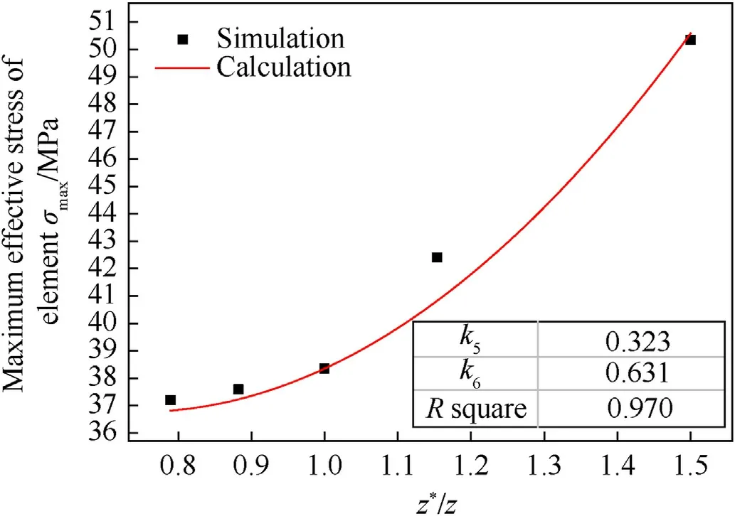
Fig.19.Maximum effective stress of the slow-release structure with different numbers of threads.
3.4.3.Influence analysis
3.4.3.1.Model establishment.To comprehensively analyse the influence of the fuse mass,the nominal diameter of the internal threads,and the number of threads on the connection strength of the slow-release structure,an analysis model for the above factors was established.From the perspective of the maximum effective stress of the slow-release structure under different working conditions,the influences of these factors are described by Eq.(3).
Here,σmaxis the maximum effective stress of the elements,M(m,m*) is the mass function,D(D,D*) is the nominal diameter function,andZ(z,z*) is the function of the number of threads.Termsm*,D*,andz*are the reference mass,reference nominal diameter,and reference number of threads,respectively.σ*is the maximum effective stress underm*,D*,andz*.In this study,m*=0.35 kg,D*=27.2 mm,andz*=15;hence,σ*=38.35 MPa.
For convenience of controlling the variables,whenm=m*,M(m,m*) =1.Similarly,whenD=D*,D(D,D*) =1;whenz=z*,Z(z,z*) =1.Fig.19 indicates that the maximum effective stress has a quadratic nonlinear relationship with the fuse mass ratio.In this paper,M(m,m*) is expressed by Equation (4) below wherek1andk2are fitting coefficients.
Here,D=D*andz=z*,and thus Eq.(3)can be expressed by Eq.(5).The simulation data was fitted with Eq.(5),and the results are shown in Fig.15 and Table 8.TheR-squared of the fitting result was 0.96,thus indicating thatM(m,m*) can describe the influence of the fuse mass on the connection strength of the slow-release structure.

Table 8Model fitting coefficients.
Fig.17 shows that the maximum effective stress is in a quadratic nonlinear relationship with a nominal diameter ratio of the internal thread.Here,D(D,D*)is expressed by Eq.(6)below wherek3andk4are the fitting coefficients.
Eq.(3)can be expressed by Eq.(7)whenm=m*andz=z*.The simulation data were also fit with Eq.(7),and the results are shown in Fig.17 and Table 8.TheR-squared value of the fitting result was 0.99,thus indicating thatD(D,D*)can describe the influence of the nominal diameter of the internal threads on the connection strength of the slow-release structure.
Fig.19 shows that the maximum effective stress is in a quadratic nonlinear relationship with the number of threads.TermZ(z,z*)is expressed by Eq.(8)below,andk5andk6are the fitting coefficients.
Eq.(3) can be expressed by Eq.(9) whenm=m*andD=D*.The simulation data were fit with Eq.(9),and the results are shown in Fig.19 and Table 8.TheR-squared of the fitting result was 0.97,thus indicating thatZ(z,z*) can describe the influence of the number of threads on the connection strength of the slow-release structure.
The model of the influencing factors is obtained by substituting Eq.(4),Eq.(6),and Eq.(8) into Eq.(3) as shown in Eq.(10).
3.4.3.2.Model verification.To verify the effectiveness of Eq.(10),FEA was carried out on the slow-release structures with different fuse mass,nominal diameter of the internal thread,and number of threads under the same loading conditions.The maximum effective stress obtained in FEA was compared with the calculation result of Eq.(10)as shown in Fig.20-Fig.22.The maximum errors between the model prediction results and the simulation results for the number of thread turnsz=13,z=15 andz=17 are 5.1%,6.3% and 5.6%,respectively.The model calculation results are in good agreement with the simulation results.The connection strength of the slow-release structure could be accurately predicted by Eq.(10)for fuse mass and dimensional parameters within a certain range.
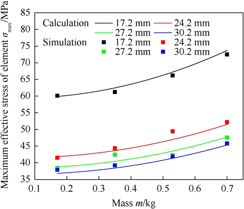
Fig.20.Maximum effective stress of the slow-release structure with different fuse masses and nominal diameter of internal threads when z =13.
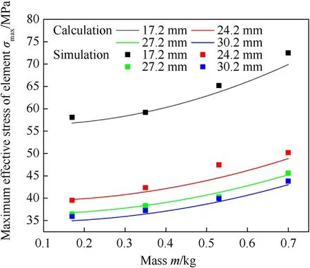
Fig.21.Maximum effective stress of the slow-release structure with different fuse masses and nominal diameter of internal threads when z =15.
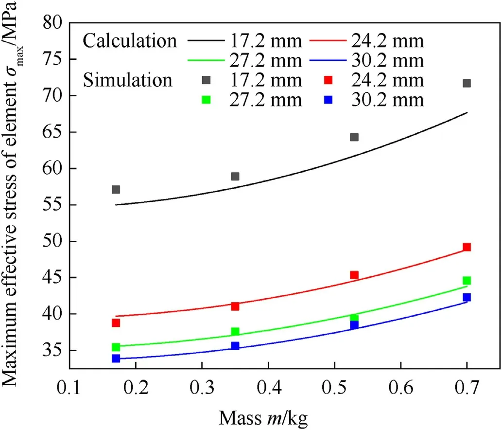
Fig.22.Maximum effective stress of the slow-release structure with different fuse masses and nominal diameter of internal threads when z =17.
4.Conclusions
Here,a polyethylene slow-release structure was designed for a 60-mm projectile that connected the fuse and the projectile body through internal and external threads.A finite element model of the projectile including the threads was established in HyperMesh software,and the dynamic response of the slow-release structure under launching overload was performed using LS-DYNA.The following conclusions were obtained:
(1) The external threads of the slow-release structure were subjected to overload before the projectile exited the muzzle and the overall load was small;this was lower than the static yield strength of HDPE.After the projectile exited the muzzle,the fuse and the projectile body separated due to the influence of the tensile wave.The internal threads of the slow-release structure were mainly subjected to the overload,and the maximum stress was at the root of the lowermost thread of the internal threads.
(2) For a given total mass of the projectile,a decreased fuse mass,increased nominal diameter of the internal threads,and increased number of threads led to decreases in the stress of the slow-release structure and the stress fluctuation,and the shorter time for stress reduction after the projectile exited the muzzle.
(3) The maximum effective stress of slow-release structure had quadratic nonlinear relation with the fuse mass ratio,the nominal diameter ratio,and the thread number.According to the influence law,a calculation model of influencing factors of the joint strength of slow-release structure was established,and the calculation results agreed well with the simulation results.However,for the prediction of joint strength of the slow-release structures of other mass projectiles,further studies are required to demonstrate the reliability of the strength model.
(4) The HDPE slow-release structure of artillery ammunition designed in this study can provide theoretical basis and technical support for the design of thermal stimulation insensitive structure of artillery ammunition.
Data availability statement
The experimental and numerical modeling results are available upon request.
Declaration of competing interest
The authors declare that they have no known competing financial interests or personal relationships that could have appeared to influence the work reported in this paper.
- Defence Technology的其它文章
- Deep learning-based method for detecting anomalies in electromagnetic environment situation
- Impact point prediction guidance of ballistic missile in high maneuver penetration condition
- Real-time localization for underwater equipment using an extremely low frequency electric field
- Numerical simulation of flow field characteristics and theimprovement of pressure oscillation of rotating detonation engine
- Comparative investigations of ternary thermite Al/Fe2O3/CuO and Al/Fe2O3/Bi2O3 from pyrolytic,kinetics and combustion behaviors
- Adaptive saturated tracking control for solid launch vehicles in ascending based on differential inclusion stabilization

