Characterization of localized corrosion pathways in 2195-T8 Al-Li alloys exposed to acidic solution
De-jun Liu,Gan Tian,Guo-feng Jin,Wei Zhang,You-hong Zhang
Rocket Force University of Engineering, College of Missile Engineering, China
Keywords:Al-Li alloy Corrosion behavior Corrosion features Immersion test Intermetallic particles
ABSTRACT The corrosion properties of aluminum-lithium (Al-Li) alloys,which are potential materials used to construct for tanks of liquid rockets or missiles,are essential for safe propellant storage and transport.In order to manifest the corrosion resistance of the 2195 Al-Li alloy in practical propellant tanks filled with N2O4,the alloy was soaked in 30% nitric acid solution,an accelerating corrosion environment,to test its corrosion behavior.Scanning electron microscopy (SEM) and transmission electron microscopy (TEM)were used to characterize microstructure and corrosion morphology of the alloy.Focused ion beam(FIB),combined with SEM,was used to demonstrate localized corrosion features and the propagation of corrosion pathways beneath the alloy surface.It was found that the corrosion network was formed with most intergranular corrosion and sparse intragranular corrosion.Additionally,the distribution and number of intermetallic particles influenced the localized corrosion degree and the direction of corrosion pathways.Aggregated particles made corrosion pathways continuously and caused more severe corrosion.The results from this work were valid and useful to corrosion prevention and protection for storage safety on propellant tanks in N2O4.
1.Introduction
Reducing the weight of liquid rockets or missiles is indispensable for increasing their range [1-3].Previous studies have reported that the loss of 1-kg weight from a liquid rocket or missile will increase their range by 15 km [4].A loaded liquid rocket or missile is always equipped with a propellant(N2O4)tank,in which tank accounts for most of the rocket or missile weight[5,6].These tanks are mainly made of aluminum-copper (Al-Cu) alloys.However,the mechanical properties of Al-Cu are worse than those of aluminum-lithium(Al-Li)alloys.Al-Li alloys have been shown to have lower density and better strength due to the addition of Li,making them potential material for tanks[7,8].At present,the 2195 Al-Li alloy is suitable for tanks and has a promising future.As the propellant (N2O4) is a strong oxidant,the corrosion resistance of Al-Li alloys,used as potential tank materials,needs to be investigated.
Corrosion properties of aluminum alloys are extremely affected by their microstructural components.Intermetallic particles,present in all aluminum alloys,played an important role in corrosion because they were generally considered to be the initiation sites for corrosion.Grilli et al.[9] revealed the cathodic nature of intermetallic particles and discovered that the sites with particles formed trenches filled with insoluble cuprous corrosion products in 2219 exposed to 3.5% NaCl solution.The cooperation between the particles has also been studied.Hughes et al.[10] found that in AA2024-T83 the cooperative corrosion was characterized by domes formed within a ring under 0.1 M NaCl.Moreover,the particle clusters involved copper enrichment.Additionally,Li et al.[11]concluded that the particles were preferential sites for the initiation of pitting corrosion due to the galvanic coupling between the anodic matrix and cathodic particles.Except for intermetallic particles,specific precipitates for Al-Li alloys also influence the corrosion behavior of alloys due to Li addition.Li et al.[12] found that the dissolutionT1and precipitate-free zone alternately caused the occurrence of intergranular corrosion and pitting due to the high activity of theT1phases in 2195 Al-Li alloys immersed in 4.0%NaCl.Furthermore,theT1phases were inclined to occur at positions with a high density of crystallographic defects and dislocation,which were associated with the heat treatment methods used in their synthesis[13].In addition,Li et al.[14]investigated the bulk ofT1phases and indicated that theT1phases could be considered to be anodic to the matrix,thus leading to preferential corrosion.Luo[15]further studied the outcomes of the assembly of theT1phases in 2A97-T6 immersed in 3.5% NaCl solution and found that assembly of theT1phases led to a relatively high amount of energy being stored in the grains,which suggested that the sites with aggregatedT1phases were more susceptible to corrosion.
By in-depth investigation,superficial corrosion does not exactly fully reflect the corrosion mechanism in aluminum alloys [16].Thus,research on the corrosion pathways beneath the surface has been carried out.Luo et al.[17],for 2A97-T3 in NaCl solution,had shown the formation of discontinuous severe pits was associated with a cluster of subsurface intermetallic particles,and the large network buried underneath the surface developed from the small openings connected to the pits.Moreover,Donatus [18] investigated the corrosion pathways influenced by the flow of anode solution and found that the pathways were dependent on the presence of secondary phases and the feature of the grain boundary in AA2198-T851under 3.5% NaCl.Zhang et al.[19] also clearly showed that the corrosion networks,formed beneath the surface,propagated along a specific grain orientation for 2A97-T6 in NaCl.Karayan [20] attributed the propagation of these corrosion networks to exfoliation behavior that resulted in the delamination of grains due to the corrosion products.Furthermore,Zhang [21]found that the distance between the selective grains and subsurface secondary phases was noticeable because closer distances led to severe corrosion in AA2024-T351.The aforementioned studies demonstrated the influence factors and research methods on the corrosion behavior of aluminum alloys under different temper and treatment conditions.However,they merely focused on the corrosion mechanism of alloys in sodium chloride solution mainly.While the corrosion behavior and propagation mechanism might vary in different media.
The corrosive environment of the tank material is caused by N2O4,which evolves nitric acid(HNO3)due to the presence of water vapor during storage.As N2O4is toxic and volatile and 30% HNO3has the fastest reaction rate with Al as based on a previous study[22,23],it is feasible to use dilute HNO3to create an accelerating corrosion environment.
In the present study,the corrosion behavior of 2195-T8 Al-Li alloys was studied using an immersion test conducted in 30%HNO3solution.By combining microscopic observations with a focused ion beam (FIB),the formation of the typical corrosion features and the propagation of the corrosion pathways beneath the surface were fully investigated.This study contributes to the comprehensive understanding of the corrosion resistance of 2195-T8 Al-Li alloys and facilitates to ensure storage safety for propellant tank in N2O4.
2.Material and methods
2.1.Samples
The chemical composition of the rolled 2195-T8 Al-Li alloys used in this study was 4.0%Cu,1.0%Li,0.03%Si,0.05%Fe,0.05%Mn,0.4%Ag,0.01%Zn,0.02%Ti and 0.14%Zr.The samples were obtained from Southwest Aluminum Co.,Ltd.and cut into 5×5 mm2pieces(with a thickness of 4.5 mm) using a wire-cutting method.
2.2.Microstructural characterization
The surface preparation was performed using mechanical polishing with silicon carbide paper(from 400#to 2000#)followed by sequential polishing with 3-μm and 1-μm diamond pastes.After polishing,the samples were cleaned via successive washing in acetone under ultrasonication and then dried using compressed air.The surface microstructure of the specimens was observed using scanning electron microscope (SEM) on a HITACHI SU8010 instrument.The precipitate distribution and type were observed using scanning transmission electron microscopy(STEM)on a Talos 200S instrument.
2.3.Immersion test
The polished specimens were immersed in flasks containing 30% HNO3for 8 h or 24 h.The mouths of the flasks were covered with a preventive film to isolate them from the external environment.After exposure,the samples were rinsed with deionized water and dried using compressed air.A ZEISS Crossbeam 550 dualbeam FIB-SEM was used to the investigate typical corrosion features and pathways beneath the surface.The Ga+beam was operated at 30 kV and 20 nA for material removal.Rectangular trenches were milled with gradually lower beam currents(down to 1 nA) in each step for finer polishing.Ion milling was paused at intervals for the SEM examination of the cross-sections of the corrosion features.
3.Results and discussion
3.1.Microstructural characteristics
The microstructural characteristics of the 2195-T8 Al-Li alloy observed from the secondary electron (SE) and backscattered electron (BSE) during SEM are shown in Fig.1.Large,elongated grains (displayed as polygonal frames) were observed along the rolling direction with many original large grains and some equiaxed recrystallized grains surrounding them,as shown in Fig.1(b).In the recrystallized grains,which were marked using colors,fine bright Cu-rich or Fe-rich precipitates (shown by arrows) with particles sizes of 1-μm size,appear to be unevenly distributed.The BSE images (Fig.1(c)-Fig.1(e)) reveal that a cluster of bright intermetallic particles,shown in dotted boxes,were distributed along the rolling direction.The composition of an intermetallic particle,marked in a yellow arrow,was detected by EDS,which was composed of 78.51 wt%Al,12.42 wt% Cu,6.59 wt% Fe,1.92 wt% Ag and 0.56 wt% Mg.Thus,the constituent particles (marked with arrows) had higher proportion of heavy metal elements relatively.The distribution and components of the particles affected the corrosion of the alloy and led to different corrosion defects,which further degrade the mechanical properties of 2195-T8 Al-Li alloy.
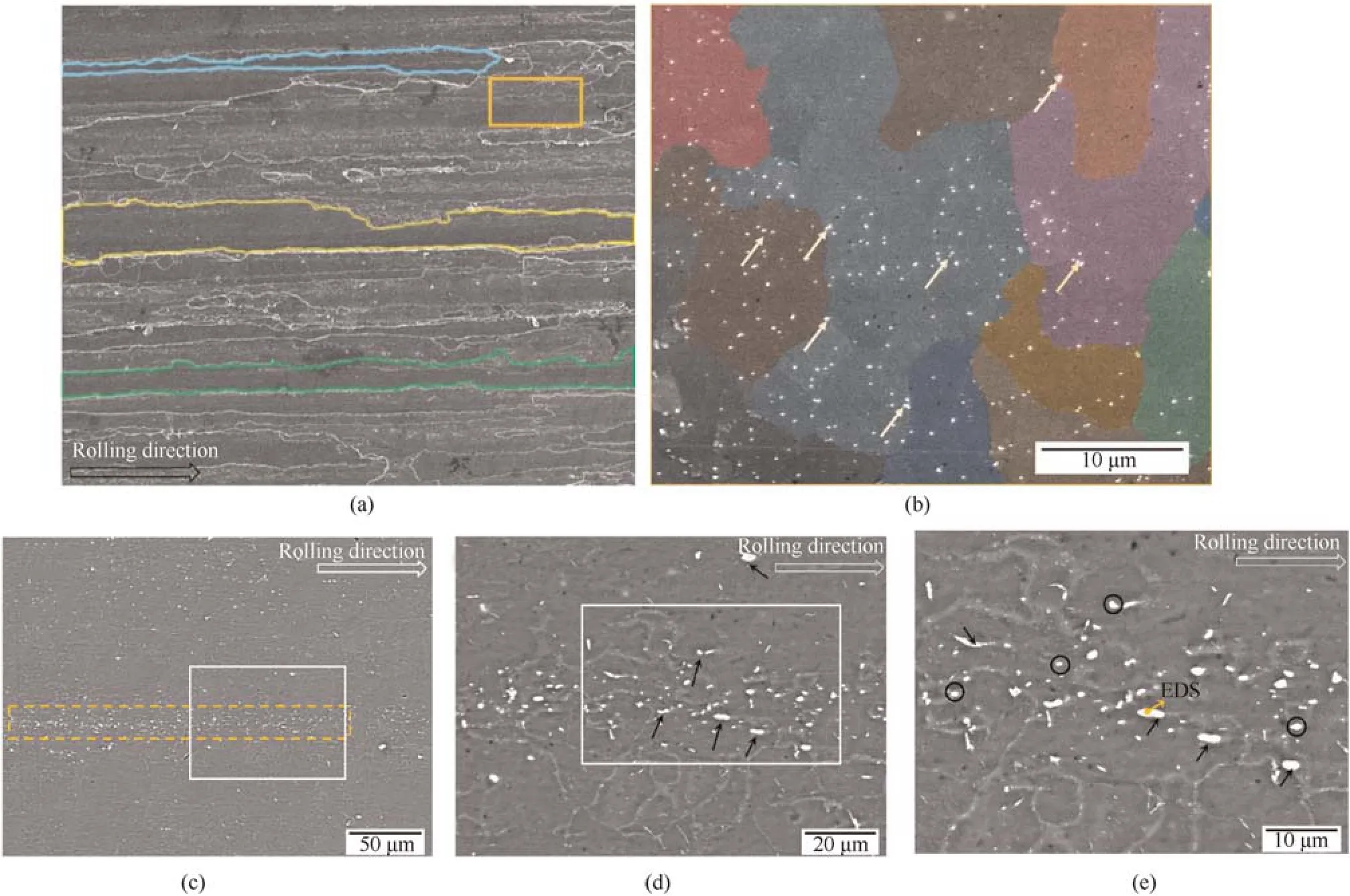
Fig.1.(a)SE image of 2195 Al-Li alloy;(b)Higher magnification of the area enclosed in the solid box shown in(a);(c)BSE image of 2195 Al-Li alloy;(d)Higher magnification of the area enclosed in the solid box shown in (c);(e) Higher magnification of the area enclosed in the solid box shown in (d).
Fig.2(a) and Fig.2(b) show the HAADF-TEM images depicting various precipitate distributions in the alloy.A typical junction of triple grain boundaries is displayed in Fig.2(a).The needle-shapedT1(Al2CuLi) was distributed in both the grains and on the grain boundaries.However,the population density ofT1along the grain boundaries was lower than that in the grain due to the heat treatment process and cold working [24,25].Furthermore,the number ofT1along grain boundary 1 was more than that along boundaries 2 or 3,suggesting the higher dislocation density in grain boundary 1 becauseT1was inclined to gather in the location with higher dislocation density and more crystallographic defects.Moreover,the brightness of grain A was higher than that of grains B and C,which indicates the existence of misorientations among the grains due to the different contrast observed in the image [26,27].Therefore,misorientations and dislocations widely exist in the alloy.Some lath-shaped θ'phases(Al2Cu)could also be observed at grain boundaries 2 and 3.Fig.2(b)is the enclosed area shown in(a)observed under high magnification.Moreover,it is noticeable that some secondary precipitates distributed sparsely on grain boundary 3,which might affect the corrosion behavior to some extent.
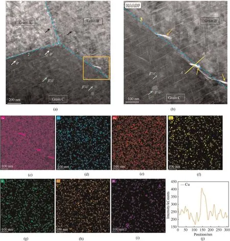
Fig.2.(a)TEM-HAADF image depicting the precipitate distribution in the alloy;(b)Higher magnification of the area enclosed in the orange box shown in(a);(c-i)EDX mapping of the various elements in (b);(j) Cu distribution along the line A-B shown in (b).
Fig.2(c)-Fig.2(j) display the EDX mapping of the various elements observed in Fig.2(b).The density of Cu was clearly higher than that of the other elements.The Cu distribution along line A-B is shown in Fig.2(j).The Cu intensity within the grains was similar,while it reached its peak on the grain boundary.This indicates that the grain boundaries and secondary precipitates were enriched with Cu.In addition,the remaining elements ranked in terms of their density were Mg,Fe,Zn,Si,Mn,and Zr,respectively.Notably,Zr was distributed mainly in grains.As Li could not be detected in EDX,the disk-shaped co-lattice β'/δ'(Al3Zr/Al3Li)phases could still be identified from the Zr distribution[18].Although the β'/δ'phases have no direct effect on the corrosion characteristics,their presence may cause oxide discontinuities,which can influence the corrosion resistance of the alloy.
3.2.Localized corrosion
3.2.1.Connected pits at grain boundaries
Fig.3(a)and Fig.3(b)show the corrosion morphologies of alloys immersed in 30% HNO3solution for 8 h and 24 h,respectively.Obviously,they represent most general pitting features on the surface etched by dilute nitric solution.Those pits were shallow and superficial,and were distributed on almost all attacked surface.However,different from those general pitting,some connected pits appeared at certain grain boundaries and grew along them (as shown by the solid arrows).In figures,positions of pits at grain boundaries had high contrast relatively,suggesting that they were deeper and more serious than the general pitting.Thus,those connected pits at grain boundaries were the focus in this section.The formation of them attributed to the interaction of high active and inert phases.As described in Section 3.1,Cu enriched along some grain boundaries.They reacted with dilute nitic solution and acted as effective cathodes for anodic dissolution of the alloy matrix or active precipitates in the vicinity.
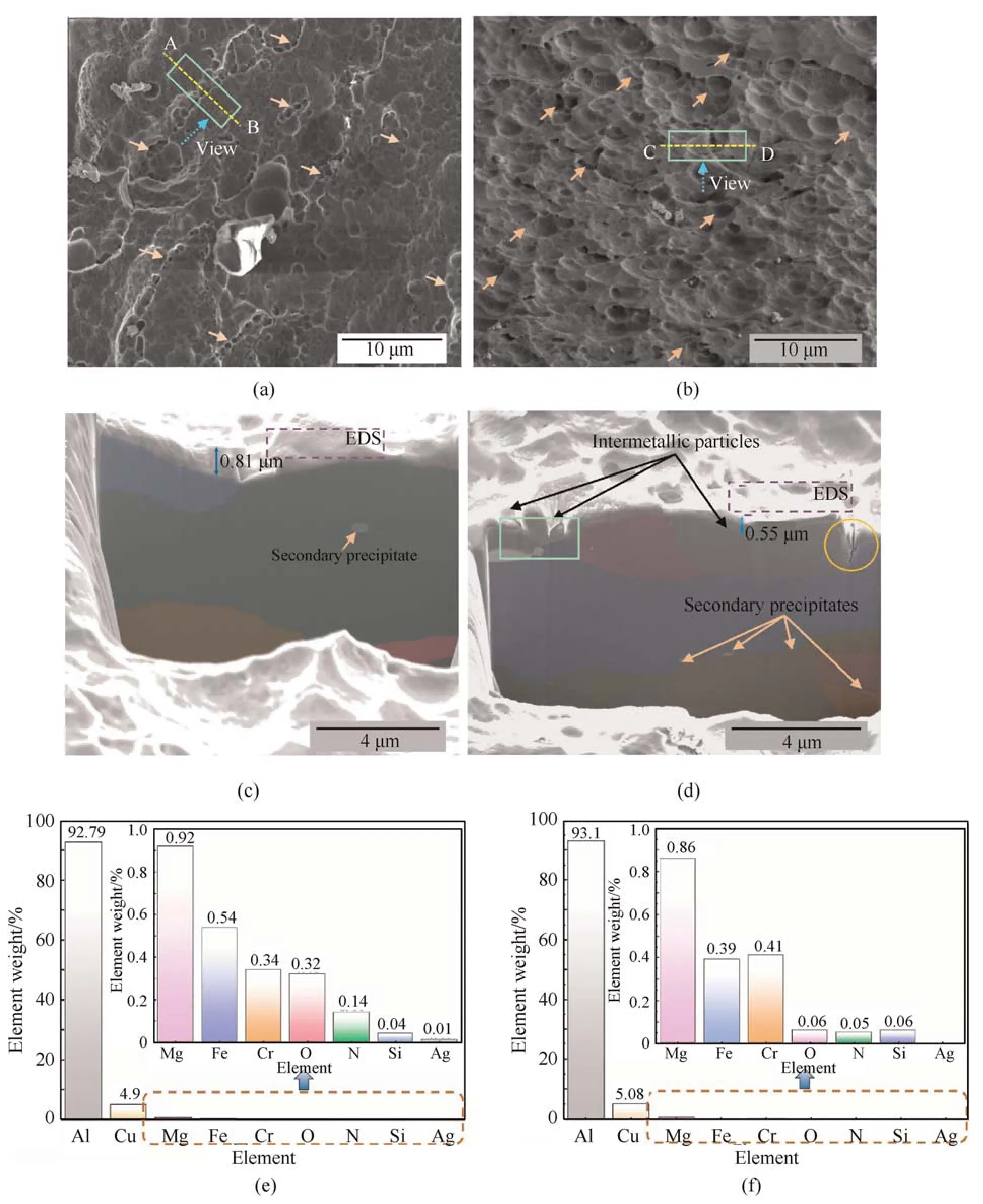
Fig.3.(a)and(b)Morphologies of corrosion pits in the alloys immersed for 8 h and 24 h,respectively;(c)Cross-section of the region enclosed in(a);(d)Cross-section of the region enclosed in (b);(e) and (f) EDS results obtained for the regions shown in (c) and (d),respectively (wt%).
Cross-sections of the sites were examined to investigate the extent of corrosion on the pits beneath the surface (Fig.3(c) and Fig.3(d)).The sectioning directions,positions,and view directions are shown by lines A-B and C-D,boxes,and dotted arrows,respectively,in Fig.3(a)and Fig.3(b).The sections reveal that those pits were linked with one to two original large grains(shown with colors)with a few secondary precipitates,which were similar to θ'or S'phases.Some of the intermetallic particles experienced dealloying during the corrosion process,resulting in the formation of pits (as shown by the dotted box in Fig.3(d)).Furthermore,on the right side of the section in Fig.3(d),a narrow trench,shown by a circle,was observed along the adjacent grain boundary,which indicates that the grain boundary had high reactive activity.This phenomenon was attributed to active phases,such asT1andS',or Cu-rich noble phases,which exhibit anodic potential or cathodic activity when compared to the matrix to promote the dissolution of the surrounding matrix [10,11].It is notable that these pits do not tend to propagate into the subsurface but appear to stop growing.Fig.3(e) and f display EDS results of the dotted regions in Fig.3(c)and Fig.3(d)respectively.It is found that Cu accounted for 4.9%and 5.08% separately,which were much higher than other elements in regions near the connected pits.Moreover,ratios of active elements,such as Mg and Fe,became less after 24 h compared to 8 h,indicating that they were consumed during the immersion test.
3.2.2.Corrosion induced by isolated intermetallic particles
Fig.4(a) and Fig.4(b) illustrate the sections of the corrosion feature caused by an isolated intermetallic particle after of immersion for 8 h and 24 h,respectively.The isolated intermetallic particle was located at the center of a stable pit.The pit was connected with a single large grain with some minor precipitates.
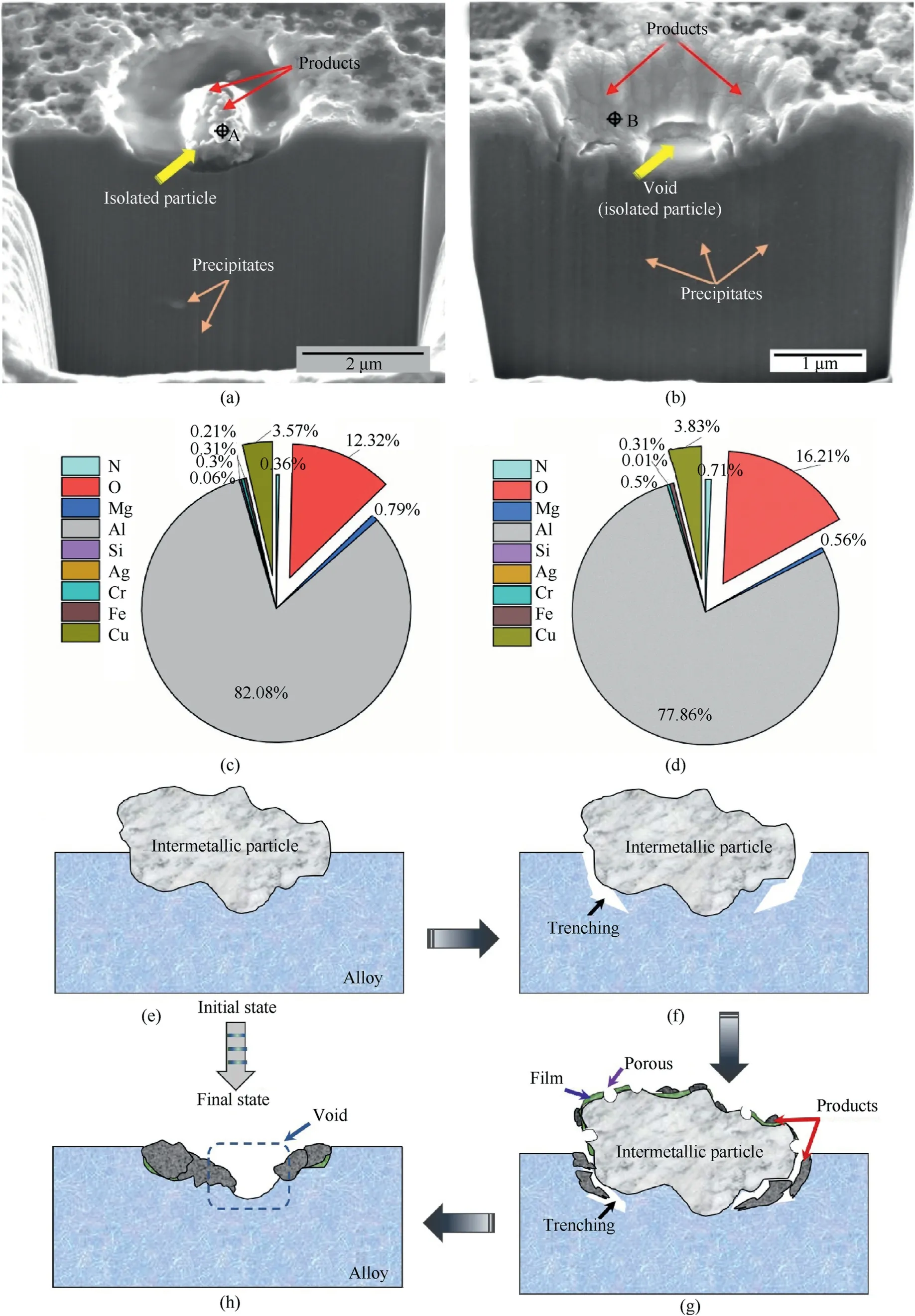
Fig.4.(a)and(b)Sections of the corrosion feature caused by an isolated particle after immersion for 8 h and 24 h,respectively;(c)and(d)EDS results obtained at the region shown in (a) and (b),respectively (wt%);(e)-(h) The corrosion process due to a single intermetallic particle.
Fig.4(a)shows that the intermetallic particle was covered with corrosion products.The outline of the pit was clear without any extra corrosion products.However,Fig.4(b)shows that the void at the center was thought to be formed by the removal of intermetallic particle during the FIB process and reflected the weakness of the particle under corrosive conditions[28-30].Obviously,the wall of the pit was covered with some products,implying that the pit was gradually sealed with corrosion products due to the dissolution of the intermetallic particle.Fig.4(c) and Fig.4(d) display the EDS results obtained at the test points (marked by crosses in Fig.4(a)and Fig.4(b).The products were rich in Cu and O and included Fe,Mg,and N,which indicate that the Cu was redistributed and oxidation products were formed during the corrosion process.
The corrosion process is shown in Fig.4(e) and 4(h).The intermetallic particle contains more heavy elements,such as Cu and Fe.It also includes some active elements,such as Li and Mg.The intermetallic particle serves as the cathode to the periphery and became the initiation site for corrosion due to its high Gibb's free energy and Cu density [13].Thus,Li and Mg in the surrounding matrix experienced preferential dissolution,and their contents in the matrix decrease as the reaction processed(Fig.4(f)).The spongy morphology of the particle indicates that the active elements act as a local anode to dissolve selectively.Moreover,previous studies[13,16,31] have shown that the existence of Li might cause defects in the oxide film formed on the particle surface.Furthermore,the acidic environment also makes the oxide film more susceptible to attack when compared with a neutral environment.Thus,the observed morphology of the particle was porous (Fig.4(g)).However,the sources of the bulk corrosion products were divided into two types: (1) the peripheral preferential dissolution and (2) selective dissolution.The deposited products might enhance the positive potential of the particle,making the matrix dissolution more active.The process involving reaction (1)-reaction (7) and reaction(8)reflects the main formation of the products due to the instability of Al(NO3)3in a dilute HNO3environment [32].
In addition,the localized attack associated with the isolated intermetallic particle was confined to the site of attack without producing any extra effects,such as etching at the grain boundaries or excessive trenching.The overall scope of attack was within 2.2 μm.Initially,the size and cathodic activity of the isolated intermetallic particle was limited.Therefore,the amount of the surrounding matrix that could be dissolved was small [12,15].Furthermore,the pit wall was brighter than the other areas,indicating that Cu-rich or noble products were formed on the inner surface of the pit.Moreover,noble products or passivated Al hinder any further reactions between the etching ions and those of the matrix as the attack proceeds.The coupling of the intermetallic particles with opposite electrochemical activity could increase the corrosion rate,and particles with mixed electrochemical nature strengthened the degree of attack [33,34].However,Fig.4(a) and Fig.4(b)show the isolated particle was not connected to any other particles,making the particle too weak to play a role in the attack.When the intermetallic particle was no longer connected with the alloy due to corrosion,the particle eventually falls from its original position eventually,leaving a void within the products (Fig.4(h)).Thus,the attack caused by the isolated intermetallic particle was limited and unable to lead to the severe mechanical degradation of 2195-T8 Al-Li alloys.
3.2.3.Severe corrosion sites
By the observation of the surface morphology of specimens after immersion for 8 h or 24 h,some severe corrosion sites with gathered particles appeared to be cloud-like.To describe the severe corrosion sites vividly,they were represented as cloud-like corrosion features.
Fig.5(a) and Fig.5(b) present the cloud-like corrosion features formed after 8 h and 24 h of immersion.Fig.5(c)and Fig.5(d)show the EDS results from Fig.5(a) and Fig.5(b) (marked with crosses).From EDS results,the composed particles in cloud-like features contained Cu,Mg,Fe,N,and O.The weight of the O element was particularly high,and the accumulated weight of O reached to 44.54%after 24 h of corrosion,which was higher than 25.36%after 8 h.That suggested that those sites experience severe corrosive attack and the severity of corrosion after 24 h was worse than that after 8 h.According to element components,the composed particles were regarded as intermetallic particles.Before immersion,the average composition of the cluster of intermetallic particles was 76.82 wt%Al,12.50 wt%Cu,6.88 wt%Fe,2.53 wt%Ag and 1.27 wt%Mg detected by EDS.By comparison,the proportion of Cu,Fe and Mg decreased all the time,illustrating the consumption with the lapse of corrosion time.Thus,the cloud-like sites were caused by cluster of intermetallic particles.The average size of a single particle was 14 μm.Furthermore,some original large intermetallic particles (displayed using dotted boxes) were divided into several parts due to the effect of etching,because the intersections of the various particles (indicated by thick arrows) were susceptible to attack when compared with the bulk particles.
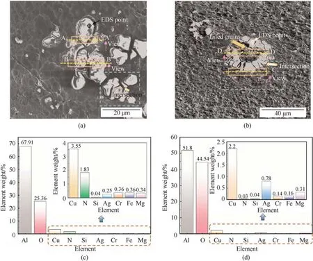
Fig.5.(a)and(b)Cloud-like corrosion features observed after 8 and 24 h immersion,respectively;(c)and(d)EDS results obtained after 8 h and 24 h of corrosion from(a)and(b),respectively.
The cross-sections of the localized corrosion sites were investigated to examine the degree of attack beneath the surface.The sectioning direction and positions are shown using dotted lines in Fig.5(a).Fig.6 shows the cross-section of A-A',whose location was near the center of the corrosion site.An isolated intermetallic particle sits in a “chamber,” which was larger than the particle itself,indicating the presence of trenches surrounding the matrix.Different from the attack of an isolated particle described in Section 3.2.2,the particle was larger and the attack tended to penetrate into the subsurface from the open border of the trench along the grain boundary,labeled as A.At locations B,C,and D,intragranular corrosion occurred and the shape of the attack was irregular.Furthermore,D was located between two grain boundaries,and the included corrosion sites were not linked to each other.Location E shows typical intergranular corrosion.On the whole,the corrosion features in the marked locations(except for A)were cut off from the bulk solution and developed along their ways.However,the occurrence of corrosion must be associated with corrosive ions and solution so as to meet the electrochemical conditions.Evidently,the section fails to fully reflect the connections [17,19].
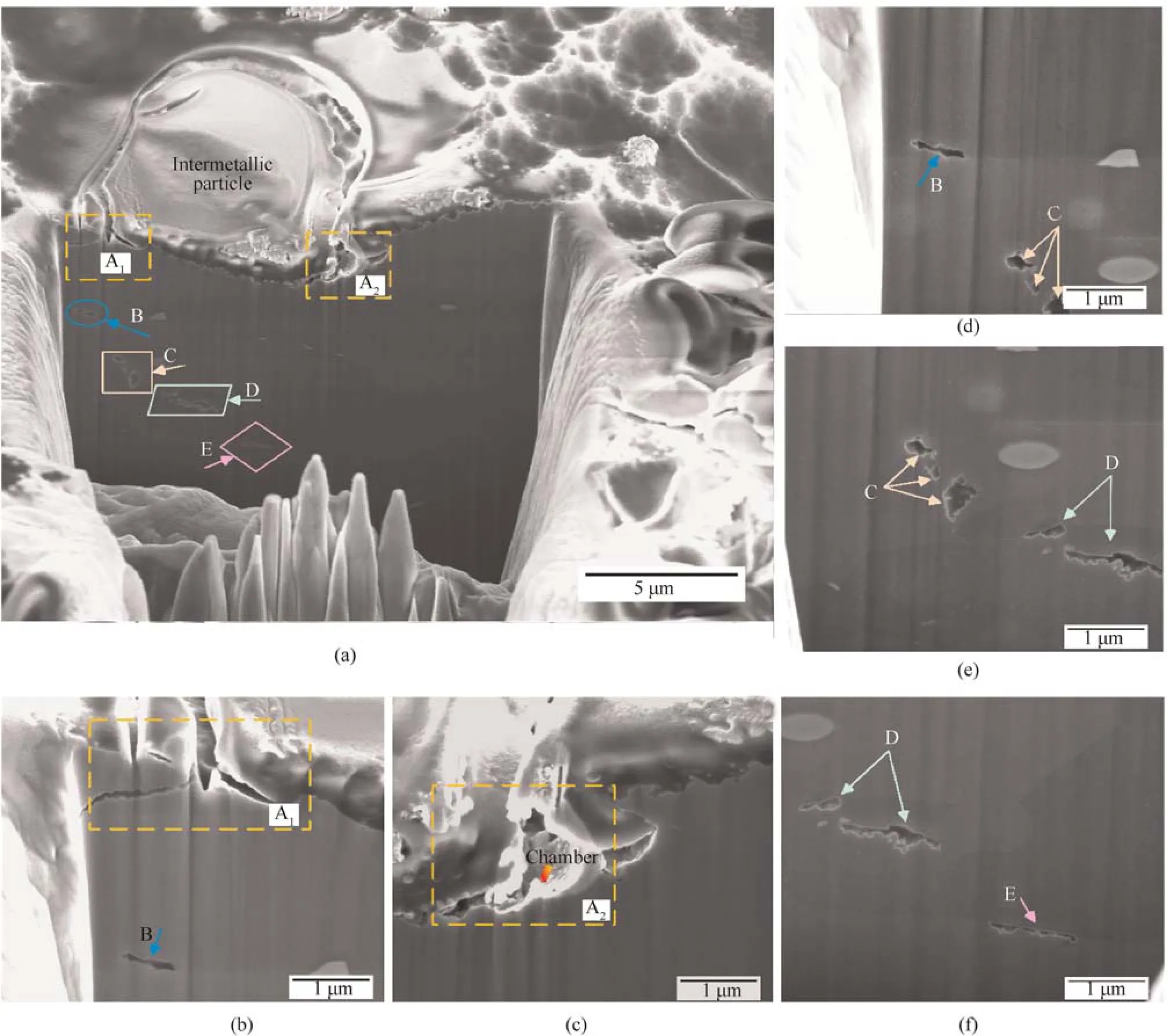
Fig.6.(a) Overview of section A-A';(b) and (c) Higher magnification of location A;(d)-(f) Higher magnification of locations B-E.
Fig.7 illustrates the cross-section of B-B'.Both intergranular corrosion and intragranular corrosion were observed,and the degree of corrosion was severe.The bulk solution mainly penetrates into the subsurface along the attacked grain boundary to further attack the alloy.The stem-like region,A,was the most severe corrosion site.As shown by the purple curved arrows,the solution enters the inner area from the path between the two grains and the nearest grain was then attacked.The single corrosion pathway appears to be divided into three branches in a single grain and many nodular structures on the grain surface.Furthermore,the attached grain was not fully attacked and leaves a part that was not eroded (as indicated by the yellow frames) due to regions with different corrosion susceptibilities in a grain.In region B,the grain experienced intergranular corrosion,and the semi-circular shape of the attack was possibly related to secondary precipitates.In region C,the intergranular attack intersects with two grain boundaries,and the downward boundary suffers more severe attacks than the upper boundary.The depths of the downward and the upper corrosion pathway were 2.5 μm and 1.3 μm,respectively.In region D,the site of intergranular corrosion was located 5.5 μm from the surface (Fig.7(f)).The initiation of this feature was from other pathways because it was not associated with the other corrosion sites observed in the section.Along the corrosion pathway,it was deflected twice during the propagation of the attack,as shown using circles.One deflection occurs when the corrosion front met two grain boundaries of two different grains.The other deflection appears due to the occurrence of precipitates.In addition,when an intermetallic particle appeared at the grain boundary,the intergranular attack progresses by dissolving the matrix surrounding it to form a chamber and a scalloping pattern.Noticeably,the grain boundary at the center of the section was almost attacked,but the etching did not go deep into the grain.This phenomenon was caused by the difference in the corrosion susceptibility or stored energy between the boundary and the inner area of a single grain.
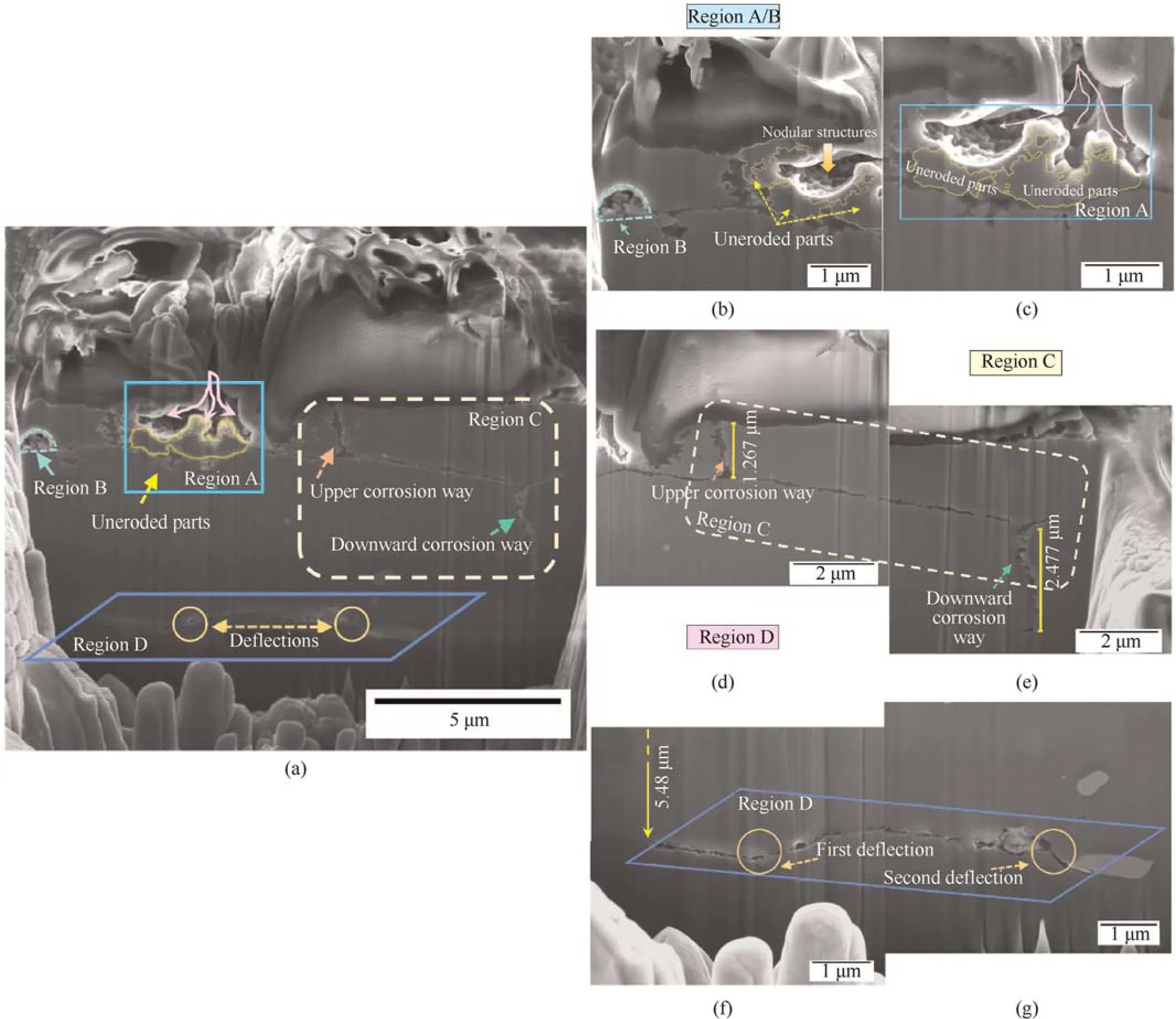
Fig.7.(a)Overview of section B-B';(b)and(c)Higher magnification of regions A and B;(d)and(e)Higher magnification of region C;(f)and(g)Higher magnification of region D.
Fig.8 describes the cross-section of C-C',indicating that the severity of corrosion after immersion 24 h of was greater than that after immersion for 8 h.A network of intergranular corrosion was observed in the section,and the attack depth could reach ≥4.7 μm.The trenches caused by intermetallic particles were at locations A and B.At location A shown in Fig.8(a),the intermetallic particle was lifted up,and a gap of about 0.5 μm from the matrix was present.Many nodular corrosion products lay in the gap,and a bright Cu-rich layer covers the substrate.At location B,a trench was formed at the edge of the intermetallic particle,but it forms a“passway” allowing corrosive attack to penetrate the corrosion network along the grain boundary.Moreover,the intergranular corrosion pathways at locations C-F appear to stop growing,and the pathway of location C was discontinuous (as shown by the enlarged view in Fig.8(b)).This indicates that the corrosive attack on grain boundaries was related to their electrochemical activity,which might be affected by the type of precipitates formed and local chemical conditions.As shown in the circles,branches of the corrosion pathway occur.Interestingly,grain A hinders the propagation of the branches.Furthermore,a hole was formed at location F,which was mainly connected with intermetallic particles,and a few products were deposited in the hole.
The cloud-like corrosion sites were undoubtedly the most severe corrosion feature among all of the characteristic corrosion features observed.Their formation was connected to the interaction formed between a cluster of intermetallic particles.Different from the isolated intermetallic particle in Section 3.2.2,the size of the particles was larger,and it was proved that higher exchange current densities and electrochemical activity could be achieved by the cluster of particles[31].The intermetallic particles that exist in 2195-T8 alloy were cathodic to the matrix because they contain elements,such as Cu,Fe,and Ag,which have higher Gibb’s energies than the matrix.Their clusters make the cathode more positive,thereby enhancing the driving force for corrosion.Consequently,the matrix surrounding the particles was dissolved and the bulk solution with corrosive ions penetrates the subsurface at a faster rate along the surrounding trenches under the effect of the cooperation of the intermetallic particles.Although the trench associated with intermetallic particles could not be observed in Fig.9,the site of corrosion initiation must be from these particles and a corrosion network was gradually formed.
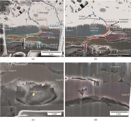
Fig.9.(a)Overview of section D-D';(b)Higher magnification of the center position of the section;(c)Higher magnification of the inner grain;(d)Higher magnification of location C.
The corrosion network was mainly caused by intergranular corrosion,while only a small amount of intragranular corrosion was observed (Fig.7 and Fig.9).The intragranular corrosion occurs in the form of random crystallographic pits.The T8 temper involves solution heat treatment,quenching,straining and artificial aging[34].Besides,the alloy would experience cold working during sheet forming.Plastic deformation might introduce some defects or dislocations,which madeT1phases be inclined to gather at those positions.The electrode potential of theT1phases was significantly more negative than that of the matrix due to the high Li content.During the corrosion process,a preferential dissolution of theT1phases occurs.However,judging from the TEM analysis in Section 3.1,the population density of theT1phase was relatively high in grains.Previous studies [35-37] have shown that the dissolution rate might decrease because Li,with its high density,could participate in the formation of a preventive film by reducing the oxygen content to increase the corrosion resistance.Thus,intragranular beneath the surface attack of 2195-T8 alloy is uncommon.However,the opposite is true for intergranular corrosion.The characteristic of the Cu-enrichment of the grain boundaries in the alloy makes them more cathodic when compared with the matrix,which results in intergranular attack.Moreover,continuous intergranular attack widely occurs in the network,which highlights the differences in chemistry between the active front of grain boundary attack and behind the boundary created by intergranular corrosion[38,39].The active front has an aggressive acidic environment,as shown in reaction (1)-reaction (6).Cu was redistributed on the grain surface behind the boundary,which indicates that a pH gradient was produced between the attack front and back.The intergranular attack was continuous because the Cu redistribution and matrix dissolution were almost simultaneous [40].
Among the features of intergranular attack,discontinuous attack and branched attack were observed,as shown in Fig.10(a).When the intergranular attack was initiated,it propagates along the grain boundary according to the aforementioned mechanism.However,when a secondary precipitate or grain boundary of another grain occurs on the pathway,the intergranular attack was stopped or branched out.This depends on the electrochemical activity of the precipitate and grain boundary.If the cathodic potential of the secondary precipitate was more positive when compared to the corrosion front region,the microgalvanic connection was reconstructed [38,41].According to the local exchange current density,the corrosion front tends to turn to the way that was susceptible to attack so as to form further branches.When the corrosion front activity was higher than the precipitate,the corrosion proceeds along the initial pathway.However,the mechanism was slightly different for the grain boundary,which is a junction of two or more grains.Under the influence of heat treatment and the manufacturing process,the misorientation or stored energy in the grains was different.The relationship between misorientation and the stored energy could be solved using the Read-Shockley equation (reaction (9)).In reaction (9),γsand θ represent the energy and misorientation,respectively,while γ0andAare constants.The stored energy increases with an enhancement in the misorientation angle.Previous studies [38,39] have showen that the corrosion front grows along the boundary with higher energy or orientation,or the corrosion process no longer occurs.Fig.8 shows the attack pathway was intermittent along the same boundary,which accounts for the scattered noble precipitates located on the boundary (Fig.3(b)).The local corrosion susceptibility and continuity were affected because the anodic activity at the corrosion front decreases due to the existence of these precipitates [19-21].
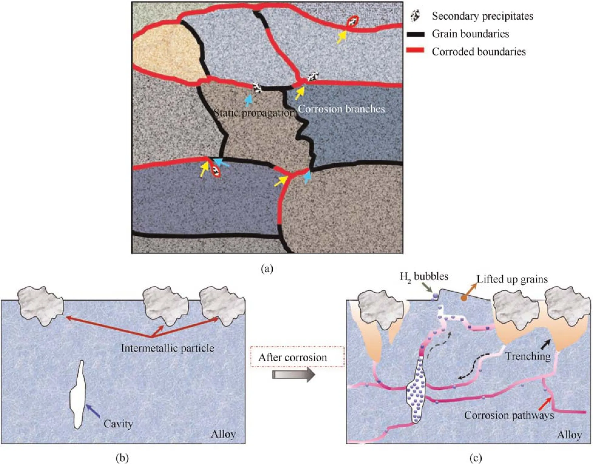
Fig.10.(a) A schematic representation of the discontinuous and branched intergranular attack pathways;(b) and (c) The attack process under the interaction of intermetallic particles,and the role of the cavity in the alloy during the corrosion process.
Interestingly,the attack becomes increasingly severe,and the grains are lifted over the alloy surface due to the interaction of the cluster of intermetallic particles upon increasing in the immersion time.The process is displayed in Fig.10(b).First and foremost,the mixed electrochemical nature of the cluster of intermetallic particles causes the dissolution of the surrounding matrix,which results in trenching and produces open pits to make the bulk solution attack into the substrate.Intergranular corrosion continuously grows along the grain boundaries to form a network of intergranular corrosion due to the high cathodic activity compared with the matrix [33,35,42].The grains were attacked much more severely,and the corroded grain boundaries connect with each other to construct an interconnected pathway [43-45].In addition,H+is produced in the intergranular network via the hydrolysis of Al and dissociation from the acidic environment evolves into H2at the acid sites and forms an aggressive corrosion front(reaction(8))[16].The H2produced is discharged to the bulk solution from the nearest pathway to the alloy surface[19-21].A large cavity appears in the alloy and become a container to accommodate the H2produced from other local corrosion sites in the network.With an increase in the immersion time,the open trench on the surface was covered with corrosion products,restricting the escape of the as-produced H2,and thus the accumulated H2gradually increases in the cavity[46].The H2bubbles increased from the cavity due to the pressure difference between the outside and cavity.Under the combination of acidic attack within the grain boundary and the rapid penetration of intergranular attack,hydrogen embrittlement might weaken the strength of the grain boundary [25].Moreover,it was found that insoluble corrosion products,if larger than the restricted region,produced within the grain boundary could induce wedging stress.This might increase the distance between the grains.Therefore,due to the pressure difference related to H2(reaction(10)),fragile grain boundaries,and wedging stress of the products,the grains would be lifted up and H2bubbles eventually discharged from the alloy.
4.Conclusions
In this study,the corrosion behavior of 2195-T8 Al-Li alloy exposed to 30%HNO3for 8 h and 24 h was studied using SEM,EDS,and FIB-SEM.Three corrosion features were observed and discussed in terms of their evolution and propagation to deepen our understanding of the corrosion resistance of alloys,which could promote the application of 2195-T8 Al-Li alloys in liquid rockets or missiles.Based on systematic investigations,the following conclusions could be drawn.
(a) The degree of corrosion in 2195-T8 Al-Li alloy becomes increasingly severe upon increasing the immersion time in dilute HNO3,and a large intergranular corrosion network is formed under the substrate.
(b) The isolated intermetallic particle causes the trenches and dissolution of the matrix and corrosion products gather around the pit wall.The capability of corrosion caused by the insolated intermetallic particle,without any other connections with extra grains underneath the surface,is extremely limited.
(c) The branch of the corrosion pathways along the grain boundary beneath the substrate is related to the activity of the precipitates and the difference among grains.
(d) Cloud-like corrosion features observed on the surface are the most severe corrosion sites among all the corrosive attack features.The corrosion network is composed of intergranular corrosion and sparse intragranular corrosion.
Declaration of competing interest
The authors declare that they have no known competing financial interests or personal relationships that could have appeared to influence the work reported in this paper.
Acknowledgements
The authors would like to acknowledge National Natural Science Foundation of China (Grant No.52075541) and Shaanxi Province Natural Science Foundation (Grant No.2022JM-243) to provide fund for conducting experiments.
- Defence Technology的其它文章
- In-plane and out-of-plane quasi-static compression performance enhancement of 3D printed re-entrant diamond auxetic metamaterial with geometrical tuning and fiber reinforcement
- Flame behavior,shock wave,and instantaneous thermal field generated by unconfined vapor-liquid propylene oxide/air cloud detonation
- Frequency domain analysis of pre-stressed elastomeric vibration isolators
- Burning surface formation mechanism of laser-controlled 5-aminotetrazole propellant
- Blast disruption using 3D grids/perforated plates for vehicle protection
- Nonlinear tight formation control of multiple UAVs based on model predictive control

