Forecast of Observing Time Delay of Strongly Lensed Quasars with the Muztagh-Ata 1.93m Telescope
Shanhao Zhu , Yiping Shu, Haibo Yuan, Jian-Ning Fu, Jian Gao, Jianghua Wu, Xiangtao He, Kai Liao,Guoliang Li, Xinzhong Er , and Bin Hu
1 Institute for Frontier in Astronomy and Astrophysics, Beijing Normal University, Beijing 102206, China; bhu@bnu.edu.cn
2 Max-Planck-Institut für Astrophysik, Karl-Schwarzschild-Str.1, D-85748 Garching, Germany
3 Ruhr University Bochum, Faculty of Physics and Astronomy, Astronomical Institute (AIRUB), German Centre for Cosmological Lensing, D-44780 Bochum,
Germany
4 Department of Astronomy, Beijing Normal University, Beijing 100875, China
5 School of Physics and Technology, Wuhan University, Wuhan 430072, China
6 Purple Mountain Observatory, Chinese Academy of Sciences, Nanjing 210023, China
7 South-Western Institute for Astronomy Research, Yunnan University, Kunming 650500, China
Abstract As a completely independent method,the measurement of time delay of strongly lensed quasars(TDSL)are crucial to resolve the Hubble tension.Extensive monitoring is required but so far limited to a small sample of strongly lensed quasars.Together with several partner institutes, Beijing Normal University is constructing a 1.93 m reflector telescope at the Muztagh-Ata site in west China, which has the world class observing conditions with median seeing of 0 82 and median sky brightness of 21.74mag arcsec-2 in V-band during the dark time.The telescope will be equipped with both a three-channel imager/photometer which covers 3500–11,000 Å wavelength band, and a low-medium resolution (λ/δλ=500/2000/7500) spectrograph.In this paper, we investigate the capability of the Muztagh-Ata 1.93 m telescope in measuring time delays of strongly lensed quasars.We generate mock strongly lensed quasar systems and light curves with microlensing effects based on five known strongly lensed quasars, i.e., RX J1131-1231, HE 0435-1223, PG 1115+080, WFI 2033-4723 and SDSS 1206+4332.In particular,RX J1131-1231 is generated based on the lens modeling results of Suyu et al.Due to the lack of enough information,the other four systems are calculated by a simple analytical approximation.According to simulations,for RX J1131-like systems(wide variation in time delay between images)the TDSL measurement can be achieved with the precision about Δt=0.5 day with four seasons campaign length and 1 day cadence.This accuracy is comparable to the up-coming TDCOSMO project.And it would be better when the campaign length keeps longer and with high cadence.As a result,the capability of the Muztagh-Ata 1.93 m telescope allows it to join the network of TDSL observatories.It will enrich the database for strongly lensed quasar observations and make more precise measurements of time delays, especially considering the unique coordinate of the site.
Key words: gravitational lensing: strong – telescopes – (galaxies:) quasars: general
1.Introduction
The Hubble constant (H0) is an important parameter for characterizing the current expansion rate of the universe.However,there is a serious discrepancy on the measured Hubble constant value between different methods Freedman(2017),Aghanim et al.(2020), Abbott et al.(2018), Riess et al.(2019), Freedman et al.(2019).One of the most traditional methods of determining H0,namely the distance ladder,uses three different distance indicators ranged from nearby Milky Way to the faraway cosmological scales.This method utilizes the parallax measurement, Cepheid variables Riess et al.(2019), the tip of red-giant branch stars(TRGB) Freedman et al.(2019) and Type Ia supernovae.The most recent controversial measurements give the best-fit value of H0=73.2±1.3 km s-1Mpc-1Riess et al.(2021),a 4.2σ in tension with the Planck cosmic microwave background(CMB) observations under ΛCDM cosmology, in which H0=67.4±0.5 km s-1Mpc-1Planck Collaboration et al.(2020).The CMB and baryon acoustic oscillation(BAO)methods currently yield lower values of H0, while Cepheids yield the highest values and TRGB results falling in the middle Freedman(2021).In order to figure out whether the tension is due to unaccounted systematic errors,or the existence of “new physics,”we need independent measurements with accuracy better than 2%Verde et al.(2019).One of the promising approach is to use the time delay between multiple images of strong lensing Oguri(2007), Coe & Moustakas (2009), Wong et al.(2020), namely“time-delay cosmography.”Light from a distant object is split and produces multiple images, when it intervenes massive objects along its path.As light travels in different paths and feels different gravitational forces,the light of images does not always reach the observer at the same time and it causes time delays.The time delays among images are affected not only by the mass distribution in the lens plane and the projected mass along the line of sight,but also depends on the cosmological background via the angular diameter distance.Hence, an accurate measurement of the time delay helps to measure the Hubble constant.
In 1964, Refsdal proposed the idea of using gravitational lensing time delay as a tool to measure H0Refsdal(1964).The first actual strong lensing measurement is done by Walsh et al.(1979).It was a quasar lensing system (Q0957+561) with a redshift of z=1.4 for the source.The first measurement of time delay was made by Schild & Cholfin (1986), and was later confirmed by Vanderriest et al.(1989).Quasars are ideal sources for “time-delay cosmography”thanks to their high luminosity and variability.To date, more and more strongly lensed quasar systems have been discovered in various surveys Oguri et al.(2006), Inada et al.(2012), More et al.(2016).More importantly, some of the lensed quasar systems have been used to measure H0Birrer et al.(2019); Wong et al.(2020).There are several teams focus on this topic, such as COSMOGRAIL,8cosmograil.orgH0LiCOW9h0licow.organd STRIDES.10strides.astro.ucla.eduThe COSMOGRAIL project began in 2004 with a mission to monitor strongly lensed quasars and measure the time delays.The collaboration monitored dozens of lensed quasars with six 1–2 m class telescopes all around the world.This network is constituted by the Swiss 1.2 m Euler telescope located at La Silla, Chile; the Swiss-Belgian 1.2 m Mercator telescope,located in the Canaria islands (La Palma, Spain); the 2 m robotic telescope of the Liverpool University (UK) at La Palma; the 1.5 m telescope of Maidanak observatory in Uzbekistan; the 2 m Himalayan Chandra Telescope (HCT) in Hanle, Indian; and the 2.2 m MPG/ESO telescope at La Silla.
A 1.93 m reflector telescope equipped with both a threechannel imager/photometer and a low-medium resolution spectrograph is currently under the construction at the Muztagh-Ata site and will be finished in 2–3 yr.Figure 1 is its conceptual design.The telescope is mainly invested by Beijing Normal University(BNU)and cooperated with Xinjiang Astronomical Observatory (XAO), Nanjing Institute of Astronomical Optics and Technology of Chinese Academy of Sciences (NIAOT) and Xinjiang University (XJU).The photometry wavelength band covers 3500–11,000 Å and spectrograph has three resolutions, δλ/λ=500/2000/7500.The field of view is 20′ with help of the correction mirror.The 300 s exposure 10σ limiting magnitude in V-band is 23.79.The telescope is designed in the R-C optical system with three focuses, namely the Cassegrain focus, the decl.axis focus and the coudé focus.The effective aperture of the telescope is 1.93 m and the focal ratio is f/8.The pixel size of CCD is 13.5 μm.The scale on the focal plane is 0 183 pix and the quantum efficiency is about 0.95.The guiding system can keep the tracking precision at the 0 3 level within 2 hr.The pointing precision is expected to be 5″ with the pointing model correction.It can be improved to the 1″ level after the secondary correction.
The Muztagh-Ata site is located at38°1 9′4 7″N and 74°5 3′4 8″E in the southwest of Xinjiang Uygur Autonomous Region of China,with an altitude of 4526 m.The full view of the site is presented in Figure 2.It is one of the best astronomical sites in China.The seeing median value is 0 82 Xu et al.(2020b).The median value of the sky brightness is 21.35mag arcsec -2 in Vband during the nighttime.For the case without moon,this number can be upgraded into 21.74mag arcsec2- (V-band).The median of relative humidity is 49% for nighttime and 39% for daytime.The median value of nighttime wind speed is 5.5 ms-1and it is 6.5 ms-1for daytime Xu et al.(2020a).All these conditions make the telescope ideal for time-domain astronomical researches.
In this paper, we forecast the capability of observing time delay of strongly lensed quasars(TDSL)with the Muztagh-Ata 1.93 m telescope.The rest of the paper are structured as follows.In Section 2, we introduce the lens modeling.Section 3 describes the simulation process.The method of measuring time delays is given in Section 4.In Section 5, we arrive our conclusions.In this study, we adopt a flat ΛCDM cosmology model with parameters Ωm=0.3 and h = 0.7.
2.Lens Modeling
In this section, we present the lens modeling, including lens basics, the lens mass distribution and brightness distribution.
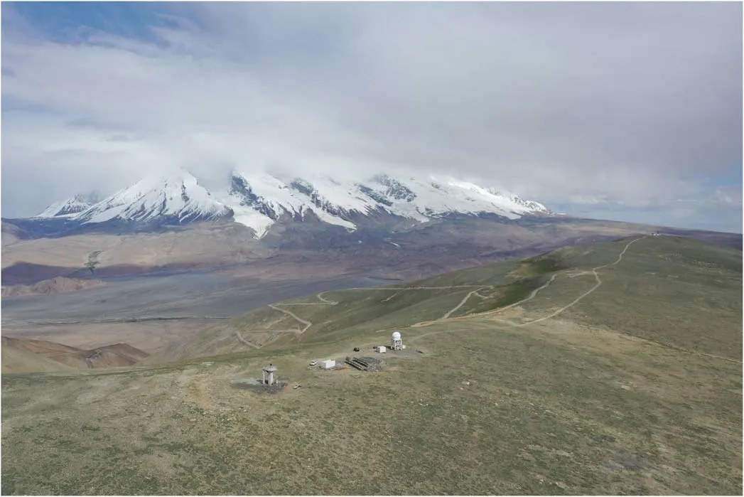
Figure 2.Full view of the site(altitude:4526 m).The white dome in the middle is a 50 cm telescope investigated by Beijing Normal University.The 1.93 m telescope is planned to be mounted next to the 50 cm one.The background mountain is Muztagh-Ata (altitude: 7509 m).
2.1.Lens Basics
We denote the angular diameter distances between the source and the lens as Dds,between the source and the observer as Ds, and between the lens and the observer as Dd.We introduce the angular coordinates in the image plane as θ,which are perpendicular to the line of sight, and angular coordinate in the source plane as β.The coordinates in the image and source planes are related through the lens equation
where α(θ) is the deflection angle, ψ(θ) is the effective lens potential and ∇θis the gradient in the image plane with respect to θ.The lens potential is determined by the dimensionless projected surface mass density κ,also the lensing convergence
is the critical surface mass density depending on the angular diameter distances.Σ(θ)is the surface mass density of the lens.The anisotropic distortion is described by the shear γ.The magnification for a point source is given by
To produce multiple images, the source must cross an infinite magnification curve, which corresponds to a denominator of 0 in Equation(4)and divides the region where the new image is generated.Such curves are called critical curves in the image plane and caustics in the source plane.The arrival time between multiple images generated by strong lensing is
where τ(θ;β) is the Fermat potential, and can be written as
When the source and the lens are perfectly aligned, the source is mapped to a ring image (the so called Einstein ring)and to a central image.Einstein radius θEis the radius of Einstein ring, which reads
where M(θE) is the two-dimensional aperture mass within the Einstein radius.More details of the lens basics can be found in Schneider et al.(2006).
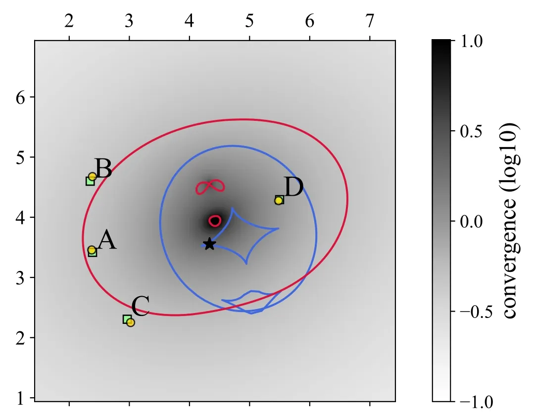
Figure 3.This figure shows the geometry of RX J1131.The scale of the view is in units of arcsec.The green boxes represent the observed positions of the quasar images.All other marks in the figure are simulation results.The asterisk indicates the position of the quasar, and the yellow circles indicate the simulated positions of the images.The blue and red curves represent the caustics and critical curves respectively.The intensity of the gray shadow represents the convergence, and only the intensity between -1 and 1 of logarithmic scale is drawn in the figure.
2.2.Mass Distribution and Brightness Distribution
Power-law profile can provide a fairly good descriptions to the mass distribution of the realistic lens galaxies Humphrey&Buote (2010), Auger et al.(2010).The dimensionless surface mass density can be written as
whereγ′ is the three-dimensional radial power-law slope,θEis the Einstein radius, and q is the axis ratio of the ellipitical isodensity contours.

where γextis the shear strength and φextis the shear angle.
The Sérsic brightness profile is an empirical model verified by a large number of observations.It has become the standard model for describing the surface brightness profiles of early-type galaxies and bulges of spiral galaxies
Baes & Gentile (2011).The brightness reads
where n is the Sérsic index.The parameter bnis a dimensionless parameter of about 2n-1/3.Reis the halflight radius (also called effective radius) which means the luminosity within Reis half of the total stellar luminosity of the galaxy.Ieis the intensity at Re, which can be calculated according to Equation(10)and the definition of Re.The Sérsic index of most galaxies is between 1/2 and 10.For elliptical galaxies, generally we have n=4, namely the de Vaucouleurs brightness distribution model Caon et al.(1993).
3.Simulation Process
In this section, we introduce the method for generating the mock light-curves of the strongly lensed quasars.The H0LiCOW collaboration Wong et al.(2020) used six strongly lensed quasar systems to constrain H0.In this paper, we pick RX J1131-1231 as a working example to demonstrate the capability of the Muztagh-Ata 1.93 m telescope of measuring time delays.This is a system with a large time delay difference between images, and there has been a lot of modeling before.We use lenstronomy Birrer & Amara (2018) to reproduce the system and simulate the observed images based on parameters fitted by Suyu et al.(2013).Then, we use photutils Bradley et al.(2020) for point-spread function(PSF) photometry measurement to obtain the observed magnitudes and the corresponding errors.Besides,we simulate another four systems, namely HE 0435-1223, SDSS 1206+4332, WFI 2033-4723 and PG 1115+080, by using the public simulation results of κ,γ and f*without lens modeling.Here,f*is the stellar mass fraction,which is relevant parameter for microlensing.For these systems, simulated images are no longer generated and the measurement errors are calculated through the signal-to-noise ratio.The corresponding results are shown in the Appendix.
3.1.Intrinsic Light-curves of Quasars
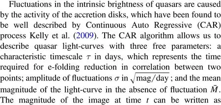

Figure 4.This figure shows the microlensing effects in the images B of RX J1131 over a four-year period, where κs=0.194, κc=0.253, γ=0.478.Here, the magnitude variation is generated by microlensing alone.The units here are astronomical magnitudes,relative to the theoretical average magnification,in other words,the magnification of the case without microlensing.For RX J1131,κ and γ are calculated from the lens modeling.f*follows previous measurements which divide κ into κs and κc.The left sub-panel is the transverse trajectory(black bar)of the quasar by assuming a point mass source model,labeled as“no convolve.”The right subpanel is the more realistic case by considering the finite area effect of the sources,labeled as“with convolve.”The box size is 4 Einstein radii of a solar mass lens.The bottom sub-panel shows the microlensing induced time variation in the case of “with convolve.”

where fluctuations are generated by the integrand.dB(s) is a normally distributed value with zero mean and variance dt.In the following simulations,we set τ=300 and σ=0.01,which are the typical values in the CAR model Dobler et al.(2015).M¯of each images are set to the observed magnitude from the CASTLES catalogs.11cfa-www.harvard.edu/castles
3.2.Lens Modeling of RX J1131
Figure 3 shows the geometry of RX J1131, simulated by lenstronomy according to the models and parameters presented in Suyu et al.(2013).It is constructed from the power-law mass profiles of the main lens and satellite lens,plus the external shear on the lens plane.The brightness distribution follows the Sérsic profile.In the figure, the asterisk indicates the position of the quasar, and the yellow circles indicate the positions of the images.These are from the lens modeling.To demonstrate the accuracy of our simulation, we also plot the observed positions of the images in green boxes.The intensity of the gray shadow represents the convergence in logarithmic scale, while the blue and red curves represent the caustics and critical curves, respectively.One can see that the positions of the images from observation and simulation almost overlap.It means that our simulation can faithfully reproduce the real observation.
3.3.Microlensing
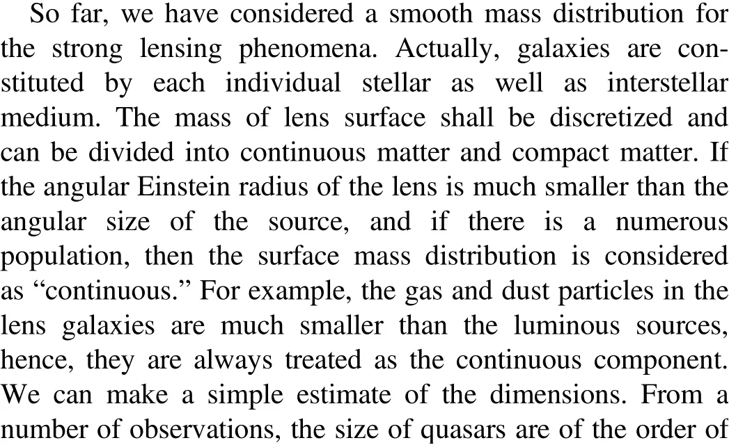
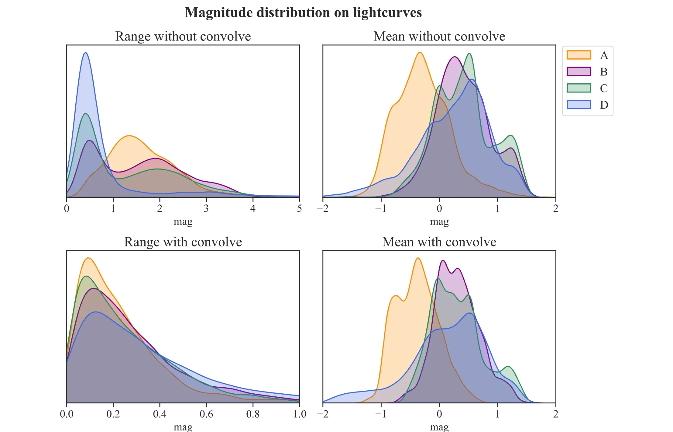
Figure 5.The probability distribution of range and average microlensing effect over the 4 yr observation period for the“with convolution”and“without convolution”cases.The statistics are obtained from 5000 randomly distributed transverse trajectories over the 4 yr observation period.
Microlensing can be thought of strong lensing at a small scale produced by compact matter.Because the image separation induced by microlensing is too small to be resolved,one can only hunt for the microlensing effect via the variation in the magnification.Here, we denote the total mass surface density as κ,the continuous mass surface density as κcand the compact mass surface density κs.Besides, we introduce the stellar fraction f* for lens galaxies, which is the ratio of the stellar mass to the total mass.The general lens equation with microlensing reads
where miscaled by M⊙represent the mass of each lens while xirepresent their positions.x is the position on lens plane and y is the position of the image.Here the positions are scaled by the Einstein radius of a solar mass lens, hereafter θ⊙.

Figure 6.Rough calculation of the observation time of RX J1131 at the Muztagh-Ata site in 2022 under some simple conditions.The observable conditions for the targets are:(1)between 30°and 80°of altitude(2)at the least 45°away from the moon.The black dashed curve in the figure represents the time between astronomical evening and morning each night(the time when the Sun’s altitude is below-18°).The gray curve represents the observable time each night.The units of these two curves are hours.The blue curve represents the proportion of observable time per night to that night.From this calculation, we can conclude that RX J1131 is observable in about 200 days over the year.
In this paper, we use FORTRAN package microlens developed by Wambsganss (1999) to simulate the magnification maps of microlensing with the method of ray shooting.The spatial distribution of the stars is random.The mass distribution is chosen to follow Salpeter’s initial mass distribution function asdN dM∝M-2.35.The maximum and minimum mass limits are 10M⊙and 0.01M⊙, respectively.Given κs, κcand shear γ, we generate magnification maps of images.Figure 4 shows the map of image B of RX J1131, in which κ and γ are calculated from the lens modeling and f*follows Chen et al.(2019)which divides κ into κsand κc.The sub-panels labeled with “no convolve”denote for the case where we treat the quasar as an ideal point source.The “with convolve”ones are the more realistic case, where we take the finite quasar source area into consideration.Hence, compared with the left, the caustics in the right sub-plots are more blurred.The convolution is done by smoothing the point source map with a Gaussian radius Rsrc=5×10¹³m.The black bar in the figure denotes for the transverse trajectory of the quasar in the source plane during the observation period, namely 4 yr in this case.We randomly pick up a direction and set the relative velocity between source and lens as vvel=500 km s-1,which is consistent with the mean velocity calculated by Neira et al.(2020)as 488 km s-1.The box size for these two magnification maps is 4 θ⊙(Einstein radii of a solar mass lens).As the redshifts of the lens and source for RX J1131 are 0.295 and 0.657, respectively Millon et al.(2020a).For RX J1131, θ⊙is 2.13 μas and Rsrc=0.11θ⊙and vvel=3.44×10⁻²θ⊙/yr.
Figure 5 shows the probability distribution of microlensing effect for the “with convolution”and “without convolution”cases.We calculate the range and average microlensing effects based on 5000 randomly distributed transverse trajectories over the 4 yr observation period under two different cases.The four images are represented by orange, purple, green and blue,respectively.It can be seen that the variation range of the microlensing curves decreases significantly after convolution while the average distribution is almost unchanged.
3.4.Cadences, Campaign Lengths and Photometric Errors
RX J1131 is a typical target located within the observable sky patch of the Muztagh-Ata 1.93 m telescope.We made a rough estimation of its observable time with two conditions:(1)the target shall be in the altitude range between 30°and 80°;(2)the target shall be 45° away from the moon at the least.According to our calculations,the observable time of RX J1131 is about 200 days per year from our site,as shown in Figure 6.Our purpose is to discuss the capability of measuring TDSL with the Muztagh-Ata 1.93 m telescope, rather than to give prediction for a specific target.Based on the field measurements at the Muztagh-Ata site Xu et al.(2020a,2020b,2020c),we believe 200 observable days per season (i.e., per year) is reasonable number for our simulations.In order to demonstrate the robustness of measuring TDSL with 1.93 m telescope,here we consider several cadences as well as observation campaign length.In details, we simulate the monitoring with 2 cadences(1 and 3 days)and 4 campaign lengths(2,3,4 and 8 seasons).

Figure 7.Illustration of the process for generating the brightness of the simulated images.Since the time delays between A, B and C are much smaller than that between A and D,in order to make the image clearer,only A and D images are drawn in this figure.Orange denotes for image A and blue for image D.The brightness of image D is reduced by 2.1 mag in the display.The panels from top to bottom show:(1)the intrinsic light-curves containing strong lensing contributions(including time delays and brightness variations); (2) the microlensing contributions in magnitudes; (3) quasar light-curves including both the strong lensing and microlensing contributions;(4)the results of down-sampling with a fiducial cadence(1 day)and season length(four seasons),which are subsequently used for the rest calculation.
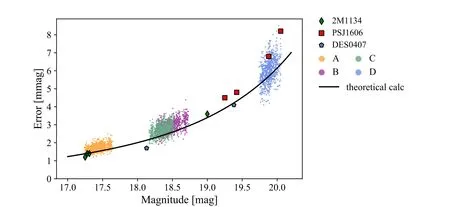
Figure 8.The brightness and photometric errors distribution of the images of RX J1131, 2M 1134, PS J1606 and DES 0407.Orange, purple, green and blue dots represent the four images of RX J1131 from PSF photometry,respectively.They are under the observation strategy of 4-season campaign length and 1 day sampling interval and each dot represents the photometry measurement in one observation night.The black curve is the theoretical calculation with signal-to-noise ratio(SNR)through Equations (A1) and (A2).The brightness of 2M 1134, PS J1606, DES 0407are similar to RX J1131.Their empirical noise σemp are represented in green diamonds, red boxes and blue pentagons in the figure, respectively.
Figure 7 illustrates the light-curve data generation process.As an example, we show the four season data with 1 day cadence.To get a better visualization effect, we only show the light-curves of the images with the maximum delay, namely image A (orange) and D (blue).To avoid the overlap in the figure, the brightness of image D is subtracted with a number 2.1 in mag.From the top to bottom, we first generate the intrinsic quasar light-curve and plus the time delay and magnification from strong lensing; then add magnification from microlensing on top of the intrinsic light variation;12Here,we only consider the magnification variation due to microlensing,but ignore the time delay induced by microlensing.and finally take the cadence effect into account.Here we assume the constant sky brightness and seeing 21.35mag arcsec-2and 0 82, respectively.The readout noise is set as Rreadout=5 e-/pix.
For RX J1131, we generate the brightness data by lenstronomy.The statistical photon errors are estimated via Monte Carlo simulations rather than the analytical formula.In each pixels, the background Gaussian noise per second is generated randomly according to the standard deviation
where nskyis counts per second per pixel from the sky brightness.The photon fluctuations of the lens images are generated according to the Poisson distribution of the brightness.Each image is obtained by tobs=300 s exposure.We call these maps as “data maps.”Besides, we generate a“reference map”with a much longer exposure time.It is used for subtraction of lens galaxy which produces the strong lensing effect and host galaxy which hosts the quasar as their brightness are invariant.The brightness used to generate each image is the result of taking into account the light transmission rate of the telescope and the quantum efficiency of the CCD.After this, the images are smoothed by the Gaussian PSF with seeing size 0.82″.We get the quasar images by subtracting the “data maps”from the “reference map”and then calculate the relative brightness via PSF photometry by photutils.At each epoch, 50 realizations of the data maps are generated, and the PSF photometric errors on the lensed images are calculated according to Equation (14), where miis the brightness of image relative to the reference map andm¯ is the mean value of mi
Figure 8 shows the brightness and photometric errors distribution of the images of RX J1131 in this work and several previous observations in TDCOSMO project Millon et al.(2020b).The orange, purple, green and blue dots represent the results of four images of RX J1131 from PSF photometry, respectively.They are under the observation strategy of 4-season campaign length and 1 days sampling interval.Each dot represents the photometry measurement in one observation night.The black curve is the theoretical calculation with signal-to-noise ratio (SNR) through Equations (A1) and (A2).One can see that the error from theoretical calculation can be taken as a fiducial value.2M 1134-2103,PS J1606-2333,DES 0407-5006 are three systems with similar brightness to RX J1131.The green diamonds, red boxes and blue pentagons in the figure represent the empirical noise σemp, corresponding to the standard deviation of the measured image flux for these three systems, respectively.It can be seen that our photometric errors are roughly at the same level as the TDCOSMO project.
4.Time Delay Measurement
In this section, we will present the time delay measurements of RX J1131 based on the aforementioned simulated four seasons light-curve data.The brightness and corresponding errors are measured as illustrated in the Section 3.4.We use PyCS,a publicly available python toolbox developed by the COSMOGRAIL collaboration Millon et al.(2020d).It is based on the iterative nonlinear optimization algorithms and is fully data-driven.It can simultaneously estimate both the intrinsic time delay as well as those induced by microlensing.A free-knot spline estimator and a regressiondifference estimator are provided.Both methods perform well in terms of precision and accuracy in the Time-Delay Challenge Liao et al.(2015).Nowadays, time delay cosmography studies are mostly based on these two methods,such as H0LiCOW and COSMOGRAIL collaborations.In this work, we use the free-knot spline estimator to measure the time delay between images and evaluate the uncertainties.This is a choice for simplification.While for state-of-art time delay measurements, the time delay measurement results are usually the combination of these two methods for a more robust uncertainty estimation
The free-knot spline estimator models light-curves with analytical spline functions.The details of the algorithm are as follows.We go first for a rough estimation of the time-delay and then refine it for adjusting the local features.The position of the knots are fixed in the rough estimation.This step is used to search the global solution,which is less sensitive to the fine structures.After that,we freely vary the knots within the range of 10 days for finding the local features.A single common spline fits simultaneously for the intrinsic variations of all images.Independent splines fit individually on each lightcurves for microlensing.The parameters of the estimator are:the initial spacing between the knots of the intrinsic spline (η)and the initial spacing between the knots of the extrinsic splines(ηml).They represent the mean spacing between knots before starting the optimization.
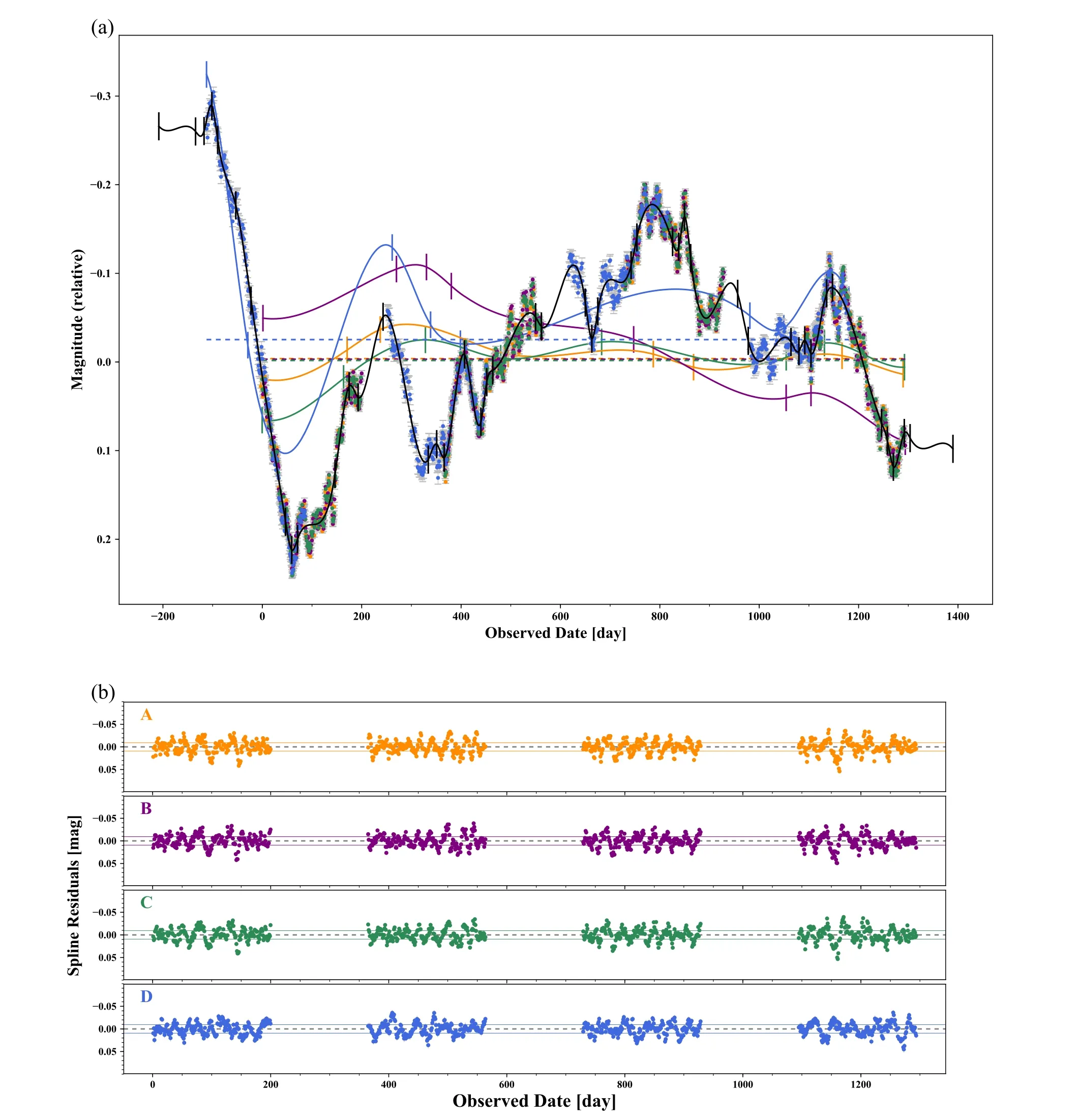
Figure 9.Fitting result of the light-curves by using the free-knot spline estimator.Figure 9(a) shows the fitting splines and curves while Figure 9(b) shows the residuals of fitting.The start time of observation starts from day 0.
In Figure.9, we show an intermediate spline fitting result with (η=35 days, ηml=150 days).The black curve is the fitting result for the intrinsic light-curve.Orange, purple,green and blue curves are the fitting results for the extrinsic microlensing effect in images A, B, C and D, respectively.13Due to the code convention,here we show the opposite brightness variation induced by microlensing.In the upper panel, we plot the relative magnitude variation with respect to the reference magnitude.One can see that the typical variation is about 0.1 mag.The bottom panels are the residuals between the input data and fitting results.The horizontal solid curves represent the median absolute deviation, which is about 0.01 mag.Hence, we can conclude that this method gives relatively faithful reconstruction of the original signal.
The time delay and its errors are estimated as follows Millon et al.(2020a).(1) We use the first guess delay as the starting point to get the preliminary measurement of time delays,splines and residuals of the fit.The first guess can be the result from the algorithm mentioned above, or simply a visual estimate.(2) In order to reduce the starting point dependence,the input light-curve is measured 500 times with starting points randomly selected around the first guess.The final time delay result is the median value of these measurements.(3) To estimate the uncertainties, we apply the estimator on mock light-curves with basically the same quality as the “real”data but different true delays.The signals in the mock light-curves are constructed with the splines instead of the data generation process presented in Section 3.The noise is generated according to the noise power spectrum obtained from the fitting residuals.The splines and residuals used here are from the estimation in step 1.By shifting these curves in time, 800 sets of curves with known time delays are obtained.By comparing the measured value with the true delay, the uncertainty can be calculated as an orthogonal combination of the worst random error and the worst systematic error.
However, the selection of parameters (η, ηml) will affect the time delay measurements to some extent.If the initial spacing was too large,some fast variations will be missed.A too small initial spacing between knots leads to an over-fitting of the data and also affects the results.Therefore, the choice of η and ηmlmust be adapted to the data quality, which mainly depends on the cadence,photometric noise,timescale of data variation,etc.As stated previously, this method is fully driven by the observed data.It is almost impossible to determine which set of(η, ηml) are the most appropriate one.
To mitigate this issue,multiple sets of(η,ηml)parameters are measured in the optimal or marginalized sense.The first version of PyCS was implemented without functioning the multi-parameter combination Tewes et al.(2013),but was later refined by Millon et al.(2020a).The improved version adopted an hybrid approach between optimization and marginalization.This algorithm marginalizes only the sets that do not have significant deviations in the measurements.This deviation,defined by the parameter τ, describes the tension between the set to be marginalized with the reference set Bonvin et al.(2018).If the tension exceeds a certain threshold τthresh, we combine the most discrepant estimation with the reference.This combined estimation becomes the new reference and we repeated this process until no further tension exceeds τthresh.Figure 10 illustrates each of (η, ηml) set result, and compare them with the combined estimation.The combined time delay measurement(gray shaded region)is shown in the upper left of each panel,which is consistent with the true delay.For a pair of images A and B,a negative value of ΔtABmeans that image A varies first, and the vice versa.Results of observations with different cadence and campaign lengths are shown in Figure 11.One can see that the measurement precision with high cadence are better than those with low cadence.In the former cases,we can achieve the time delay measurement error at the 0.5 day level with four seasons campaign length.This is our major result of this paper.
5.Conclusions
The Muztagh-Ata site is one of the best astronomical sites all over the world.The seeing median value is 0 82.The median value of the sky brightness is 21.35mag arcsec -2 in V-band during the nighttime.For the case without moon, this number can be upgraded into 21.74mag arcsec -2 (V-band).An effective aperture 1.93 m reflector telescope is currently under the construction phase leaded by Beijing Normal University in China.This telescope is equipped with both a three-channel imager/photometer (wavelength covers 3500–11,000 Å) and a low-medium resolution (δλ/λ=500/2000/7500) spectrograph.The field of view is 20′ with the help of the correction mirror.The 300 s exposure 10σ limiting magnitude in V-band is 23.79.All these numbers indicate that the 1.93 m telescope is an ideal telescope for monitoring the light variation of the lensed quasar system.
Based on the observation conditions of the Muztagh-Ata site and the instrument parameters of the 1.93 m telescope, we simulate the lensed quasar observations with different cadences and campaign lengths, and forecast the precision of the measured time delay.We model quasar intrinsic light-curves,microlensing effect as well as the PSF photometric errors.We simulate RX J1131 with with lens modeling based on published parameters in the main text and other four systems without lens modeling in the Appendix.According to simulations, for RX J1131-like systems (wide variation in time delay between images) the time-delay observations of strongly lensed quasars can be achieved with the typical precision about Δt=0.5 day with four seasons observation and 1 day cadence.This precision is comparable to the up-coming TDCOSMO project Millon et al.(2020c).
This paper presents a preliminary study of the time delay for strongly lensed quasars with the Muztagh-Ata 1.93 m telescope.The sky brightness and seeing are considered as constant, slightly ideally.Some of the sub-leading order systematics, such as the position of planets and moon, air humidity and weather has not yet been taken into account.We studied the time delay measurement precision with different strategies,which are characterized by the campaign lengths and sampling intervals.When increasing the cadence to one day,we are able to reach a very precise measurement of the time delay in a short campaign rather than decades of observations.As a result, the capability of 1.93 m telescope allows it to join the network of TDSL observatories.It will enrich the database for strongly lensed quasar observations and make more precise measurements of time delays.We believe it will help resolve the Hubble tension.
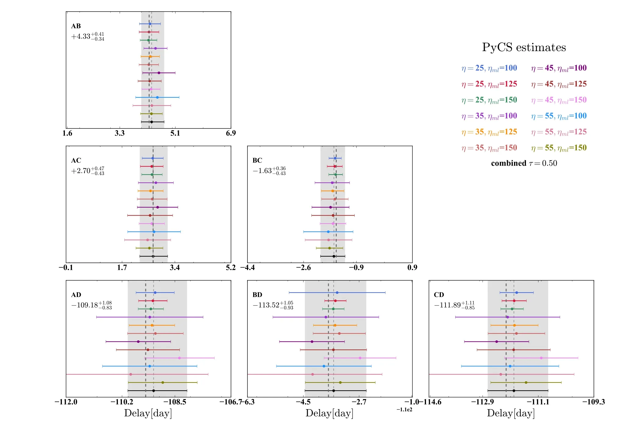
Figure 10.Series of time-delay estimation with different parameters and their combination.Each time-delay estimation shown in the figure corresponds to a particular choice of parameters, namely the mean spacing between the knots of the intrinsic spline η, and of the extrinsic splines ηml.The combined estimation which corresponds to a threshold of τthresh=0.5 is shown in black at the bottom, and its uncertainty is indicated as gray shaded band.Dark gray vertical dashed line represents the true time delay.

Figure 11.Series of time-delay measurements relative to image A with different observation strategies.Each time-delay estimation shown in the figure corresponds to a particular choice of observation strategies,namely the campaign length(season)and sampling interval(cadence).The results are given from the combined time delay measurement, with the algorithm described in the text.The combination threshold parameter is chosen as τthresh=0.5.The true time delays are shown with gray vertical dashed curves in the figure.
Acknowledgments
We thank Sherry Suyu and Frederic Courbin for discussion and comments.This work is supported by the China Manned Space Project with No.CMS-CSST-2021-A12, the National Natural Science Foundation of China under Grant Nos.11973016, U2031209, 11873006 and U1931210.Y.S.acknowledges support from the Max Planck Society and the Alexander von Humboldt Foundation in the framework of the Max Planck-Humboldt Research Award endowed by the Federal Ministry of Education and Research.
Appendix Another Four Systems
In the Appendix, we show the results of another four strongly lensed quasar systems, namely HE 0435-1223, SDSS 1206+4332, WFI 2033–4723 and PG 1115+080.The time delays of these systems do not differ much from each other.Since we lack the sufficient information for these four systems,we directly use the publicly available simulation results of κ,γ and f*of them.In this case,we do not need to generate the lens images and can directly simulate the light-curves.Instead of using the PSF photometry,here we use the analytical method to calculate the photometric magnitudes and errors.The generation of intrinsic light-curves follows Section 3.1 with the CAR process.τ and σ are set to 300 and 0.01, respectively.M¯ of each image corresponds to observed magnitudes from CASTLES and Gaia.14The brightness of SDSS 1206 is missing in CASTLES, so we use that of Gaia.We adopt previous measurements Millon et al.(2020a), Bonvin et al.(2018), Bonvin et al.(2019),Birrer et al.(2019)as true delays of these light-curves.Several important parameters (κ, γ, f*) for microlensing magnification maps are listed in Table A1 and are used to generate microlensing effect as 3.3.The photometric error is calculated through the signal-to-noise ratio (SNR), which is defined as
Then, we convert it into the photometric error in magnitudes Howell (2006)
where npixis the number of pixels covered by the image, mainly determined by seeing.The value of 1.0857 is the correction term between an error in flux (electrons) and that same error in magnitudes.We normally distribute random values with zero mean and standard deviation from Equation (A2) onto the brightness images.Frankly speaking, the error given in Equation (A2) is slightly optimistic.As a forecast paper, this number sets the upper limit of the photometry measurement of the Muztagh-Ata 1.93 m telescope.Results of different observation strategies are shown in Figures A1, A2, A3 and A4.Table A2 shows the time delay measurements under the observation strategy of 3-season campaign length.The time delay measurements for these four systems can achieve good accuracy under this observation strategy.

Figure A1.Series of time-delay measurements of HE 0435 relative to image A with different observation strategies.The notations are the same as Figure 11.

Figure A2.Series of time-delay measurements of PG 1115 relative to image A1 with different observation strategies.The notations are the same as Figure 11.

Figure A3.Series of time-delay measurements of WFI 2033 relative to image A1 with different observation strategies.The notations are the same as Figure 11.
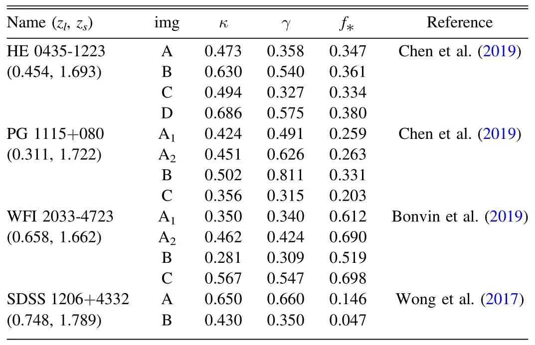
Table A1 Lensing Parameters for Creating the Microlensing Magnification Maps
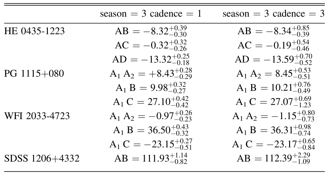
Table A2 Time-delay Measurements Relative to the First Image
ORCID iDs
Shanhao Zhu https://orcid.org/0000-0002-3676-2416
Xinzhong Er https://orcid.org/0000-0002-8700-3671
 Research in Astronomy and Astrophysics2023年3期
- Research in Astronomy and Astrophysics的其它文章
- Discrepancy in Grain Size Estimation of H2O Ice in the Outer Solar System
- Galactic Dark Matter Halos Containing H I Regions: A Possible Overestimation of the Column Densities
- Limiting Magnitudes of the Wide Field Survey Telescope (WFST)
- Quality Control of YFOSC Data I.The On-site Quick Analysis System
- Principal Component Analysis of Ground Level Enhancement of Cosmic Ray Events
- A Morphological Study of Two Young Multipolar Planetary Nebulae
