Generation of a blue-detuned optical storage ring by a metasurface and its application in optical trapping of cold molecules
Chen Ling(凌晨) Yaling Yin(尹亚玲) Yang Liu(刘泱) Lin Li(李林) and Yong Xia(夏勇)
1State Key Laboratory of Precision Spectroscopy,School of Physics and Electronic Science,East China Normal University,Shanghai 200241,China
2School of Physics and Astronomy,Sun Yat-sen University,Zhuhai 519082,China
3Collaborative Innovation Center of Extreme Optics,Shanxi University,Taiyuan 030006,China
Keywords: metamaterials,beam characteristics,trapping of molecules
1.Introduction
A metasurface can precisely control the degrees of freedom of the phase, polarization and amplitude of an incident light field.[1-3]It provides a new way to develop the next generation of experimental platforms for atomic and/or molecular quantum-state manipulation on chips by virtue of the tight spatial confinement and high local intensities.Currently, varieties of novel optical components, such as lenses, mirrors,waveguides, gratings and polarization controllers, have been successfully developed using a metasurface structure.[4-6]So,the miniaturization of ultra-cold atomic experimental devices has become possible,and an all-optical metasurface route for an atom (or molecule) chip has been proved to be a good platform for building a robust quantum laboratory.[7-12]For example, atomic magneto-optical trap (MOT) schemes based on metasurfaces have been reported.In 2013, a reflectiontype atomic MOT experiment based on a metasurface grating was reported and 6×10⁷Rb atoms were trapped.[7]In 2020,a metasurface transmission-type atomic MOT was reported,which trapped 107Rb atoms at about 35µK.[8]In 2021,using planar optical elements for beam launching,beam shaping and polarization control,a grating-type MOT for Rb was realized,which captured 2.8×10⁶atoms below 200µK.[9]
One important application of metasurfaces is metalenses.[13]For example, metal- and dielectric-type metalenses have been used to focus light to the near or far field in the visible or infrared region.[14-18]Previously, our group proposed a two-dimensional subwavelength silicongrating reflector with strong focusing capability, resulting in an intensely focused spot and ring at the focal plane of the metalens.[19-21]The molecules were drawn to the maximum in the red-detuned light field under the influence of the optical dipole force, which serves as a dipole trap.In comparison,when the light field is blue detuned,the interaction potential is repulsive,and the molecules will be repelled to the minimum in the light field.In this case, molecules will be trapped or guided in a blue-detuned hollow beam.[22,23]A hollow beam storage ring based on this effect has unique advantages: the deep potential enables trapping of molecular wave packets whose average velocity is not zero; the low photon scattering rate and long trap lifetime enables the interaction of molecules with other molecules or electromagnetic fields many times at the specific location and time.Such features of the storage ring provide an effective way to study high-resolution molecular spectroscopy,ultra-cold collisions and reactions.[24-27]In contrast to electric or magnetic field storage rings, an optical storage ring can trap any molecule regardless of its dipole polarity and paramagnetism.Although the scheme of the blue-detuned metasurface storage ring possesses some unique advantages,it has not been fully realized until now.
Herein,we present a new scheme for generating a focused hollow beam storage ring on a subwavelength silicon-grating metasurface with potential application as an optical dipole trap for cold molecules.This paper is organized as follows.We first give a detailed description of the design principle of the storage ring,determine the high transmission rate by optimizing the height, cycle and duty rate of the structural element and then design the hybrid phase with a combination of the focusing phase and theπphase.Then, we construct a threedimensional focused hollow beam storage ring at the focal plane of the metalens, and study the intensity distributions of the storage ring in free space and its propagation characteristics.Finally, we use Monte Carlo simulation to study the dynamics of MgF molecules in the storage ring.
2.Design of the metasurface structural element
The desired phase modulation was achieved by modifying the effective index within each cell based on effective medium theory.[28]The phase jumps of the electromagnetic wave at the metasurface can be written as Δφ=2πneffd/λ, whereλis the incident wavelength,drepresents the thickness of the element andneffrepresents the effective refractive index of the element.Since a phase-transmitting-type metasurface is nearly two-dimensional and the thicknessdis generally kept unchanged in the manufacturing process, the phase accumulationφis realized by changing the effective refractive indexneffat different positions.[20,22]Change inneffis generally achieved by constructing a material microstructure of a higher refractive index on a substrate of a lower refractive index.
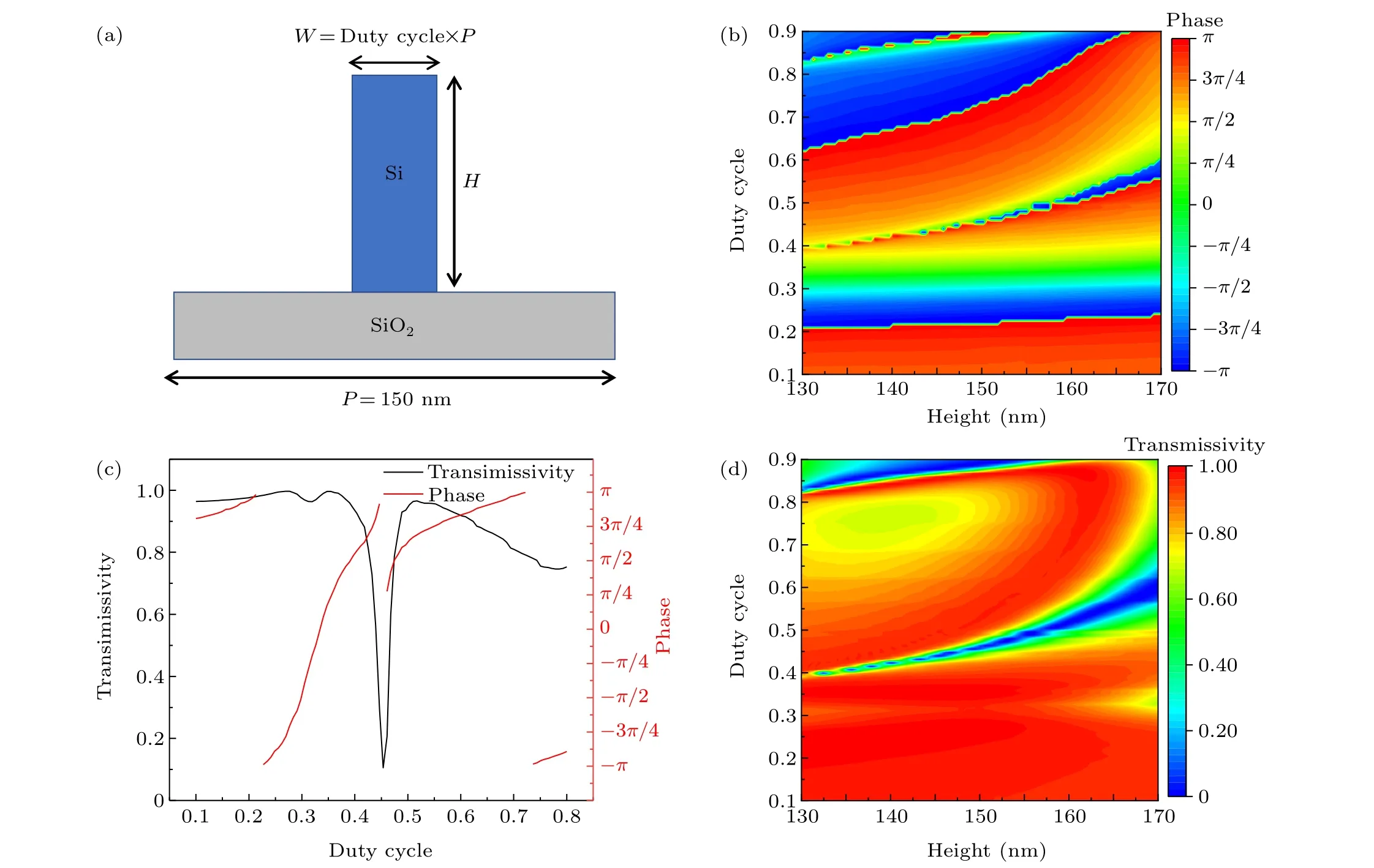
Figure 1(a)shows the periodic structural element applied in the metasurface.The substrate is SiO2material and the microstructure is Si, which grows on the substrate.To achieve the desired blue-detuned hollow beam storage ring, the incident wavelength is chosen to be 300 nm.The width of the SiO2substrate in one period is set asP=150 nm, the width of the Si column is set asWand the height is set asH.Note that the duty cycle isW/P.By varying the structure of the Si column, the effective refractive indexneffat different positions on the metasurface can be adjusted.The thicknessHcan be kept constant.To satisfy the phase requirement for the hollow beam intensity distribution,the phase of the grating is designed to have a focusing effect and a completely destructive interference function at the focal plane;the phase distribution should cover the range-πtoπ.So,we scan different ranges of structural parameters to find the optimalH.Meanwhile,we keep the transmissivity of the structure as high as possible.

Fig.1.(a) Design of the structural Si column element with a width W and height H on the SiO2 substrate with a period P=150 nm.Dependence of the corresponding phase(b)and transmissivity(d)of the light on the parameters of the height and duty cycle of the structure,respectively.(c)The transmissivity(black curve)and phase(red curve)as a function of duty rate.
By changing the height and duty cycle of the grating,the phase and the transmissivity of the light can be modulated, as shown in Figs.1(b) and 1(d), respectively.When the heightHis around 151 nm, by simply changing the duty cycle we can cover the range-πtoπof the phase distribution with high transmissivity.Then,taking the optimal heightH=151 nm,the simulated results by changing the silicon duty cycle are obtained,as shown in Fig.1(c).The red curve indicates that the phase covers the range-πtoπwhen the duty cycle of the grating changes from 0.1-0.4 and 0.5-0.6.The black curve indicates that the cell structure maintains a transmittance of more than 90%when the duty cycle changes from 0.1-0.4 and 0.5-0.6.In this way,we finally determine the optimal structural parameters of the periodic cell:P=150 nm,H=151 nm, duty cycle between 0.1-0.4 and 0.5-0.6, all of which will be used to tune the transmission phase.
3.Intensity distribution of the metasurface storage ring
The structure of the metasurface storage ring comprises a concentric silicon grating and a SiO2substrate.The design principle is that the phase arrangement of the concentric grating array in the radial direction can focus the incident light to the focal plane to form a hollow optical ring, as shown in Fig.2.Figure 2(a)shows a schematic diagram of the formation of a metasurface hollow ring.Figure 2(b)shows a picture of a crossed section of the designed grating in the radial direction.Such a one-dimensional grating array can be expanded into a two-dimensional grating ring array by rotating one circle,and then incident light can converge to the focal plane, forming a focusing ring.In order to generate the hollow beam distribution,the hybrid phase of the grating is designed to have a focusing effect and a completely destructive interference function at the focal plane.For a grating structure with focusing capability,the phase shift of the transmitted light needs to satisfy the phase distribution equation of the convex lens.Using the finite element simulation,an optimal concentric grating array is found comprising 107 elements with 53 elements symmetrically distributed to each side of the central element.Here,we use the phase distribution of the metalens to converge the light to one point, then combine the phase of Fig.3(a) with aπphase plate,shown as a grey annulus in Fig.3(b)with an inner radiusraand an outer radiusrb.The solid grey annulus has the same area as the remaining white area, but there is aπphase difference between the grey and white parts.When the light first passes through the focusing phase regime(in Fig.3(a)),it will form a convergent light field.Then,through theπ-phase regime(in Fig.3(b)),two parts of the light will result in a completely destructive interference effect at the focal plane.Two kinds of phases can be combined into a new one(in Fig.3(c)).Therefore,the optical intensity near the focal point will be reduced to a minimum and a focused hollow ring beam is generated above the grating metasurface.

Fig.2.Diagram of the design principle of the metasurface storage ring.(a) Three-dimensional schematic of the formation of a metasurface ring light field.The blue arrows represent the incident direction of the beam and the black arrow represents the radially polarized direction.(b)View of the cross section of the half grating(shown as the red rectangle).The red circle is the focal hollow beam formed by the half grating,rc is the center position of the half metasurface grating and rn is the center position of each metasurface structure element in Fig.1(a).(c)The corresponding phase distribution: the red solid curve is the required phase and the blue dot is the discrete phase value required by the structure.

Fig.3.(a)Phase distribution of the focusing lens.(b)Phase plate with a phase difference of π.(c)Hybrid phase distribution of(a)and(b).
The specific phase distribution in Fig.3(c)can be written as
wherercis the center position of the half metasurface grating in Fig.2(b),rnis the center position of each metasurface structural element in Fig.1(a),raandrbare,respectively,the inner and outer radii of the grey annulus in Fig.3(b),fis the focal length,λis the wavelength of incident light,Pis the width of the SiO2substrate in one period andφnis the phase value needed for the metasurface structural element with central positionrn.
Taking the focal lengthf=7.8 µm as an example, we calculate the required phase distribution for each metasurface structural element according to Eqs.(1) and (2).We set the central position of the first metasurface structural element asr1=2.65µm and the central position of the 107th element asr107=18.55µm.As shown in Fig.2(c),the solid red curve is the required continuous phase curve,indicating that the phase required to form the metalens is between 0 and 2π.If the phaseφnis greater than 2π, it can be mapped to a value between 0 and 2πwhich gives the same results.In this way,according to the corresponding curves of phase in Fig.1(c),the duty cycle of each structural element can be obtained.Then, the widthWof each structural element is acquired.Thus, we can get the structural parameters required for the design of the whole grating array.The blue dots in Fig.2(c) represent the actual discrete phase values corresponding to the 107 elements.
The final parameters designed for the storage ring arermin= 2.575 µm,rmax= 18.625µm, annular widthRw=rmax-rmin= 16.05 µm.We define the numerical aperture of the annular metasurface asNA=sin(tan-1(Rw/2f)).The expected focal lengthf0is 7.8 µm, the radiusr'is 10.5 µm andNAof the grating is around 0.717.
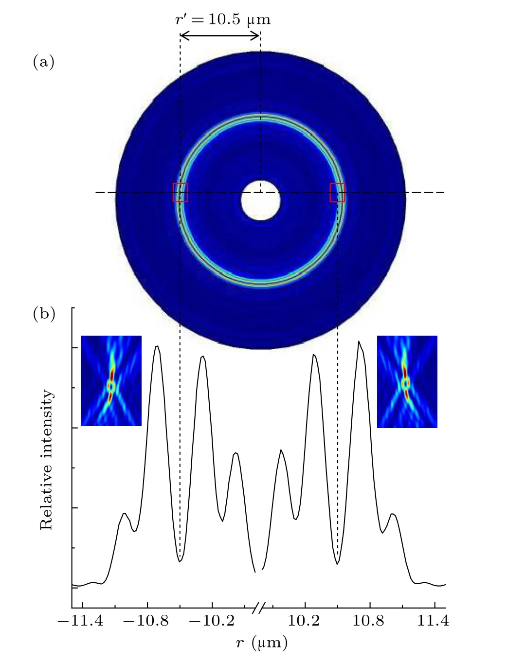
Figure 4(a)shows the optical intensity distribution of the hollow optical ring at the focal plane.The radius of the ringr'is defined as the distance between the position of the minimum light intensity in the hollow ring beam and the center of the meatsurface grating,which is 10.5µm.Figure 4(b)shows the corresponding one-dimensional light intensity distribution along any one of the diameters at the focal plane.There is a closed hollow area in the intensity profile at the focal point.In the focal plane,the intensity distribution looks like a valley,as seen in Fig.4(b), and the two peaks are on either side of the hollow profile.We define the highest peak asEmaxand the bottom of the valley asEmin.It can be seen from Fig.4 that the maximum light intensity of the ring is 10.4(relative to the minimum intensity in the center of the ring.

Fig.4.Intensity distribution of a ring light field on the focal plane of the metasurface storage ring: (a) two-dimensional and (b) one-dimensional intensity distribution at the focal plane,respectively.The insets in(b)are the two-dimensional light intensity distributions shown in the red rectangle in(a).
Due to machining errors in the period and duty cycle parameters of the grating strips when processing the grating,aberration inevitably occurs when the metalens focuses the light.We study the influence of the missing number of round grating strips on the focusing performance of the storage ring.We randomly select the missing grating strips to investigate the corresponding light intensity at the focal plane,and the results are shown in Fig.5.We can see that for a concentric grating,a focal length of~7.8µm remains but the ratio of|Emax|2to|Emin|2at the focal plane generally decreases as the number of missing grating strips increases.This means that the depth of the optical potential well would not be large enough to trap molecules with many missing strips.

Fig.5.Relative light intensity(left y-axis)and corresponding focal length(right y-axis) of the optical ring as a function of the number of missing grating strips.
4.Monte-Carlo simulation of optical storage rings
A variety of techniques, such as Stark/Zeeman deceleration, electric/magnetic trapping and storage rings, have been developed to manipulate molecules in both position and velocity space.[24-27]A characteristic of the electrostatic potential well of polar molecules is that there is a lowest point of potential energy in space with which to form a circle in space.The advantage of a storage ring is that it can manipulate molecular wave packets whose average velocity is not zero;these molecules can repeatedly interact with other molecules or electromagnetic fields at the specific locations and times.However,all existing methods are only applicable for trapping cold polar or paramagnetic molecules,not molecules without a permanent electric or magnetic dipole moment.In contrast,an all-optical storage ring of cold molecules does not require the molecule to possess a permanent electric or magnetic dipole moment but induces an electric dipole moment to generate gradient forces to confine molecules into a potential trap.[20,22]Moreover,it is naturally immune to Majorana-type spin flips,which lead to the loss of trapped molecules.Therefore,the optical storage ring could have a broader range of applications.
Previously, we have proposed such an all-optical storage ring by shining an incident red-detuned laser on a metasurface.[21]Despite having the above-mentioned advantages over a traditional electric/magnetic storage ring, the trapped molecules will be subjected to an obvious heating effect and consequent decoherence, as the molecules are attracted to the position with the highest light intensity.Here,we propose an optical storage ring utilizing blue-detuned light and the metasurface.For the blue-detuned traps,generally the molecules are trapped in the minima of the optical field, and the photon scattering rate is very low,[22]leading to the minimum heating effect and a long coherence time.Herein, we will discuss the feasibility of this blue-detuned storage ring,which can indeed form a deep optical potential for trapping cold molecules.

Fig.6.Trapped MgF molecules in the focused hollow beam formed by the metasurface grating: (a)optical potential curve,(b)dispersive dipole force curve.
We chose the MgF molecule as an example; this a typical alkali-earth fluoride molecule that has recently been laser cooled in our lab.[29-34]We calculated the optical dipole potential and its dipole force for MgF molecules.When a neutral molecule enters a blue-detuned inhomogeneous light field,it experiences an optical dipole force described by an optical trapping potential
Here,αis the polarizability of the molecule,pis the dipole moment andI(r)is the optical intensity distribution.The average polarizability of MgF isα=4.56×10-40C·m2·V-1andkis the Boltzmann constant.The dipole force is a conservative force, proportional to the intensity gradient of the field.When the light field is blue detuned, the interaction potential is repulsive and the molecules will be pushed to the minima of the light field.Therefore, molecules will be trapped in a blue-detuned hollow beam.The blue-detuned laser wavelength is 300 nm relative to the resonant energy level of the MgF molecule.[29]The metasurface grating has a widthRw=16.05 µm and focal lengthf=7.8 µm.At the focal plane, the optical potential and the dipole force along the radius direction are shown in Fig.6.The optical potential of the blue-detuned hollow beam for MgF molecules at the focal plane is calculated from Eq.(3), and the result is shown in Fig.6(a).The effective optical potential is 90 µK at the focal plane, high enough to trap cold MgF molecules from a gray molasses at temperatures as low as a few µK.In addition, the maximum photon scattering rate of MgF molecules in the optical trap is lower than 1 s-1.Due to the minimum light field in the central region of a hollow beam, the heating of trapped molecules is low,leading to long trapping lifetime.It can be seen from Fig.6(b)that the maximum dipole is 9.8×10⁻²¹N,which is at least 1.3×10⁴times greater than the gravity force for MgF molecules.This shows that the dipole force is strong enough to balance the action of the gravity force on the molecules.The red dashed line in Fig.6(b)corresponds toFdip=0,and the red point represents the center of the potential well whose coordinate isr=10.5 µm at the focal plane,which is exactly the point of the minimum intensity at the center of storage ring.
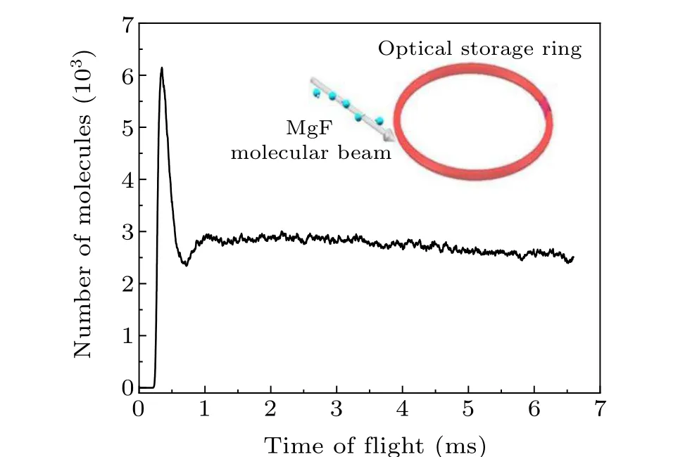
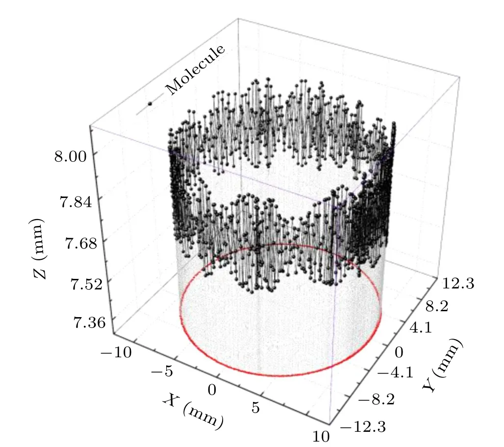
To analyze the longitudinal motion of molecules and their transverse stability in the storge ring, a three-dimensional Monte Carlo simulation is performed.[34]The schematic diagram is shown in the inset of Fig.7.The simulation conditions are as follows:105cold MgF molecules are loaded from a single pulse of a laser-slowed beam with a mean velocity threedimensional translational temperature of 50 µK and incident direction along the tangential direction of the storage ring,as shown in Fig.7.In the simulation,the detection volume is approximated by a cylinder,which represents the intersection between the detection Gaussian beam and the half-circumference relative to the entrance of molecular beam on the storage ring.The number of molecules evolving over time in the detection region is investigated and the results are shown in Fig.7.Due to the finite width of the velocity distribution in the molecular beam,the beam extends along the circumference and becomes elongated.This leads to an early arrival at the detection region by the fast portion of the loaded molecular beam.In the first two rounds of encirclement,the number of detected molecules reaches a maximum of 6.2×10³and 3.0×10³att1=0.34 ms andt2=1.02 ms,respectively,instead of the expected 0.55 ms and 1.65 ms,according to the mean velocity.Afterwards,the loaded molecular wave packet quickly spreads out along the circumference,as is evident from the simulated time-of-flight spectrum in Fig.7.Then, the number of detected molecules starts to follow an exponential decay with an estimated lifetime of more than 35 s due to further spreading with time.The loading efficiency is estimated to be 6% due to a large velocity distribution compared with the mean velocity.This can be greatly improved by transversely focusing the molecular beam, for example by a standing wave.Figure 8 shows a three-dimensional diagram of the trajectory of a single MgF molecule in the storage ring.The motion of the molecule in thezdirection is within the range of 0.4 µm near the focal plane.The red curve is the projection of the trajectory onto thex-yplane,and the molecule moves in therdirection near the radius of the storage ring.These results demonstrate that the proposed storage ring has excellent properties for trapping cold molecules and maintaining their quantum state coherence due to a negligible heating effect and a very long lifetime of trapped molecules.

Fig.7.Time-of-flight spectra of the MgF molecular beam circling in the storage ring.The inset is a schematic diagram of molecule detection.

Fig.8.Three-dimensional motional trajectory of a single MgF molecule in the surface storage ring.The red curve is the projection of the molecular trajectory on the x-y plane.
5.Conclusion
In this paper we have proposed a new scheme for generating a focusing hollow ring beam by using a transmission-type metasurface and have calculated the intensity distributions and the focusing characteristics.We found that under the incident polarized 300 nm laser illumination the metasurface can generate a hollow ring with a focal length of 7.8 µm and a linewidth of 0.4µm.At the focal plane,the maximum intensity of the hollow beam is over 10.4 times its minimum intensity.The effective optical potential is 90µK at the focal plane,large enough to trap cold molecules from a gray molasses at temperatures as low as a few µK.The blue-detuned hollow beam storage ring possesses many unique features, such as a low photon scattering rate and long trap lifetime for a variety of molecular species that can be laser cooled.Finally,we use the Monte Carlo method to simulate the dynamics of the MgF molecules in the optical storage ring.After loading the molecules in the storage ring for about 1 ms, the number of molecules tends to be stable at about 3.0×10³and they spread to the whole optical storage ring space.Moreover,the blue-detuned storage ring is expected to have many applications in high-resolution molecular spectroscopy and ultra-cold collisions and reactions.[34]
Acknowledgments
Project supported by the National Natural Science Foundation of China(Grant Nos.12174115,11974434,91836103,and 11374100), the Natural Science Foundation of Guangdong Province, China (Grant No.2020A1515011159), the Science and Technology Program of Guangzhou (Grant No.202102080380), and Shanghai Pujiang Program (Grant No.20PJ1403400).
- Chinese Physics B的其它文章
- Matrix integrable fifth-order mKdV equations and their soliton solutions
- Comparison of differential evolution,particle swarm optimization,quantum-behaved particle swarm optimization,and quantum evolutionary algorithm for preparation of quantum states
- Explicit K-symplectic methods for nonseparable non-canonical Hamiltonian systems
- Molecular dynamics study of interactions between edge dislocation and irradiation-induced defects in Fe-10Ni-20Cr alloy
- Engineering topological state transfer in four-period Su-Schrieffer-Heeger chain
- Spontaneous emission of a moving atom in a waveguide of rectangular cross section

