
Beam alignments based on the spectrum decomposition of orbital angular momentums for acoustic-vortex communications
2022-12-28 09:54:02GepuGuo郭各朴XinjiaLi李昕珈QingdongWang王青东YuzhiLi李禹志QingyuMa马青玉JuanTu屠娟andDongZhang章东
Chinese Physics B 2022年12期
Gepu Guo(郭各朴) Xinjia Li(李昕珈) Qingdong Wang(王青东) Yuzhi Li(李禹志)Qingyu Ma(马青玉) Juan Tu(屠娟) and Dong Zhang(章东)
1School of Computer and Electronic Information,Nanjing Normal University,Nanjing 210023,China
2Haiying Enterprise Group Co.,Ltd.,Wuxi 214061,China
3College of Ocean Science and Engineering,Shandong University of Science and Technology,Qingdao 266590,China
4Institute of Acoustics,Nanjing University,Nanjing 210093,China
Keywords: acoustic-vortex beam, beam alignment, orbital angular momentum (OAM) spectrum, least standard deviation,acoustic communication
1. Introduction
Like the optic vortex beam, the acoustic-vortex (AV)beam has spiral wavefronts[1]with a pressure null at the central axis. As a type of contactless acoustic tweezer,[2–6]the orbital angular momentum (OAM)[7–9]carried by AV beams can be transferred to objects to rotationally manipulate particles,which is of significant interest for applications in biomedical engineering.[10,11]In addition to the acoustic radiation force or torque, the topological property of AV beams[12]based on their orthogonal characteristics[13]can be used to transmit data with an improved spectral efficiency in acoustic communications. The quality of acoustic communications can be improved by the OAM transmission of AV beams[14]with an enhanced channel capacity. With a transducer array,the phase-control technique was designed to construct OAMmultiplexed AV beams with an improved controllability of data transmission,and accurate OAM decoding[15,16]was accomplished based on the orthogonality of OAM modes for fields detected in the transverse plane.
With a 20-channel circular source array and a square receiver array, images were transmitted underwater by using OAM-multiplexed beams.[17]In addition, eight fan-like sections of resonators composed of four Helmholtz cavities placed in series[18]were assembled around the central axis to convert plane waves into AV beams. The structure was also used to decode OAM by adding or subtracting[19]the topological charge of the OAM-multiplexed beams. For traditional orthogonality based decoding, the accuracy and efficiency of OAM decoding are affected by the multiple pre-measurements of single-OAM beams and the long time required for data processing. To accelerate OAM decoding,investigations have focused on OAM communication with AV beams by using a simplified structure of single-ring transceiver arrays,[20]and the OAM spectrum decomposition has been optimized by using rotational measurements of OAM-multiplexed beams without premeasuring of single-OAM beams.[21]
Although the advantages of the OAM-based acoustic communication have been demonstrated in previous studies,accurate data decoding can only be accomplished under the ideal reception conditions of strictly aligned beams for coaxial transceiver arrays or structures placed in parallel. For a misaligned system of non-coaxial or non-parallel transceiver arrays, erroneous OAM decoding is introduced by an inaccurate circular pressure distribution with imperfect phase spirals. Therefore, misaligned beams have been investigated to develop new alignment methods in optics and acoustics.
Based on the Fraunhofer diffraction of a Gaussian beam through a spiral phase plate,[22]asymmetric diffraction patterns were produced by displacing the optical axis of incident beams. The intensity distribution along the maximum asymmetric direction had two separate peaks with the intensity ratio decreasing exponentially with off-axis displacement.The OAM spectrum[23]was used to analyze the angular inclination of the optical axis for a vortex beam based on variations between the tilt angle and the beam axis with different topological charges, and the phase delay caused by the axial tilt was obtained by angular inclination. The OAM spectrum corrected by the calculation is applicable to single-OAM and OAM-multiplexed beams. Shin[24]analyzed how a uniform circular array affected the channel capacity under non-ideal reception,and the results showed that the off-axis or non-parallel placement of transceiver arrays could lead to a reduced channel capacity.
Based on the relationship among the angular deflection,the off-axis translation distance and the arrival time of the received signal, a time-to-arrival (ToA) method was proposed to compensate for non-ideal reception conditions. A receiving scheme involving improved partial aperture sampling[25]was proposed based on the characteristics of the zero-intensity center of an electromagnetic vortex field. The bit error rate(BER)of data transmission was increased with increasing radial deviation and angular deflection of the receiver array. A scheme[26]for exponential OAM modulation was then developed involving an electromagnetic vortex emitted by a uniformly distributed ring-array of antennas. The BER increased with the deflection angle of the transceiver arrays with aligned centers. To avoid the decreased channel capacity of uniform circular arrays in non-parallel cases produced by the deflection of the receiver array,a beam-guided method[27]was proposed to avoid array misalignment. Thus,unlike traditional communication systems, the OAM-based AV communication can be accomplished by transceiver arrays with a perfect alignment of the coaxial placement in parallel, otherwise, the quality of data transmission decreases significantly due to the introduced crosstalk and errors.
Previous studies show that, data communication via AV beams depends mainly on the structure of source arrays and the orthogonal characteristics of OAM modes.Accurate OAM decoding can only be implemented under ideal reception conditions without considering the influence of array translation or deflection. In practical applications,transceiver arrays with a simplified circular structure and convenient control should be developed to transmit data in real time. The possible impact of non-ideal reception due to array displacement or deflection should be considered. Thereby, the beam should be aligned to improve the accuracy and stability of OAM-based acoustic communication. Assuming ideal reception,the spectrum decomposition method may be used to accurately decode OAM modes without requiring multiple measurements of single-OAM beams in advance. However, the OAM spectrum is also affected by the non-ideal reception of misaligned acoustic beams. Therefore,the OAM spectrum can serve as a sensitive indicator of beam alignments.
To overcome the shortcoming of the orthogonality-based OAM decoding algorithm and improve the efficiency for AV communications,beam alignments of transceiver arrays based on the OAM spectrum decomposition is proposed in the current study. For single-ring transceiver arrays ofNtransmitters andMreceivers, a theoretical model of OAM spectrum decomposition is constructed for OAM-multiplexed beams. Numerical simulations of the single-OAM and OAM-multiplexed beams indicate that, due to the OAM dispersion, the error of the OAM spectrum increases with the translation distance and the deflection angle of transceiver arrays. Ideal reception conditions of coaxially placed transceiver arrays in parallel, two methods of the sing-array translation alignment and the dualarray deflection alignment are developed based on the criterion of the least standard deviation of OAM spectrum(SD-OAM).With transceiver arrays consisting of 16 transmitters and 16 receivers, the effects of beam alignment are verified by the multiple adjustments of the translation and deflection in three dimensions with a decreasing SD-OAM towards zero. The simulation results of the OAM dispersion and the SD-OAM are consistent with experimental measurements for misaligned beams. These results demonstrate the feasibility of the rapid beam alignment based on the OAM spectrum for AV beams by using a simplified structure of single-ring transceiver arrays, which opens the door to more applications in acoustic communications.
2. Principle of OAM spectrum decomposition
As shown in Fig. 1, an OAM-multiplexed beam is constructed by a ring-array ofNtransducers with the spatial angle of ∆ϕ=2π/Nbetween adjacent sources,where the source radiusais much smaller than the wavelength. To build a single-OAM beam with the topological chargel, the initial phaseϕln=[2π(n−1)l]/Nof then-th source is applied based on the phase-coded approach,wheren=1 toN. Thus,the acoustic pressure in free space can be described by
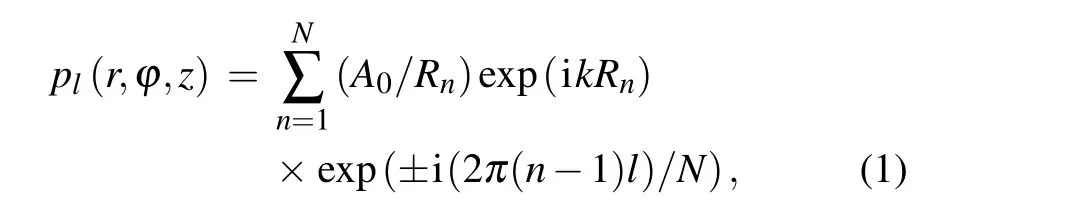
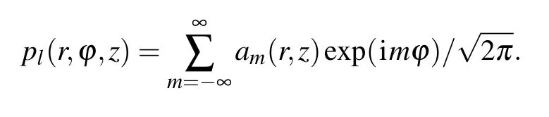
whereA0is the source pressure,Rnis the distance between the observation position(r,ϕ,z)and then-th source(a,ϕn,0),andk=ω/cis the wave number withcandωbeing the speed of sound and the angular frequency, respectively. For a ring-array with a finite source numberN, the maximum OAM of the AV beam islmax=⎿(N −1)/2」,[28]where⎿x」roundsxto the nearby integer towards zero. Meanwhile,the cross-sectional distribution of a single-OAM beam at the transmission distancezcan be optimized topl(r,ϕ,z)=A(l,r)exp(iψ(l,r))exp(ilϕ),whereA(l,r)is the radial pressure distribution[29]andψ(l,r)+lφdenotes the phase spiral around the vortex center. Therefore, by superimposing theScoaxial single-OAM beams,the acoustic pressure of the OAM-multiplexed beam[20]can be written as
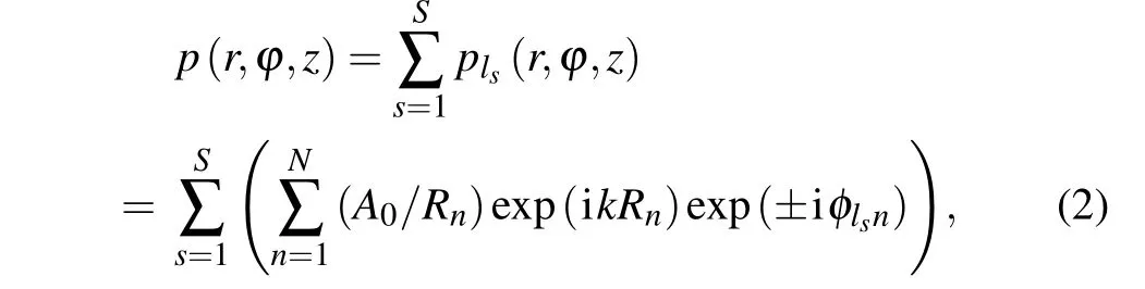
wheresrepresents the number of single-OAM beams with the topological chargelsin[−lmax, lmax]. Thus,the acoustic pressure can also be expressed as the summation ofSsingle-OAM beams asp(r,ϕ,z)=∑Ss=1A(ls,r)exp(iψ(ls,r))exp(ilsϕ). A center-AV with the center located atr=0 can thus be generated bySsingle-OAM beams except forls=0,[30]and several off-axis AVs with|p(r,ϕ,z,t)|=0 positioned around the beam axis withr/=0 can also be created.Therefore,a complicated acoustic field can be generated by the OAM-multiplexed beam, as shown in Fig. 1. The beam is determined by the topological charges of the single-OAM beams with the corresponding initial phases.
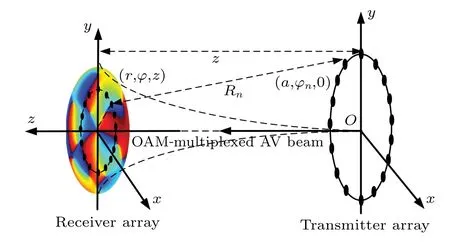
Fig.1. Schematic diagram of constructing OAM-multiplexed AV beams and acoustic measurements based on single-ring transceiver arrays.
The spectrum decomposition method[23]can be used to analyze the OAM dispersion for AV beams. The complicated AV beam can be expanded into a linear superposition of spiral harmonic functions exp(imϕ),[31,32]wheremis the integer OAM order. For a single-OAM beam of orderl, the acoustic pressure can be described by The coefficient of them-th OAM component can be calculated by
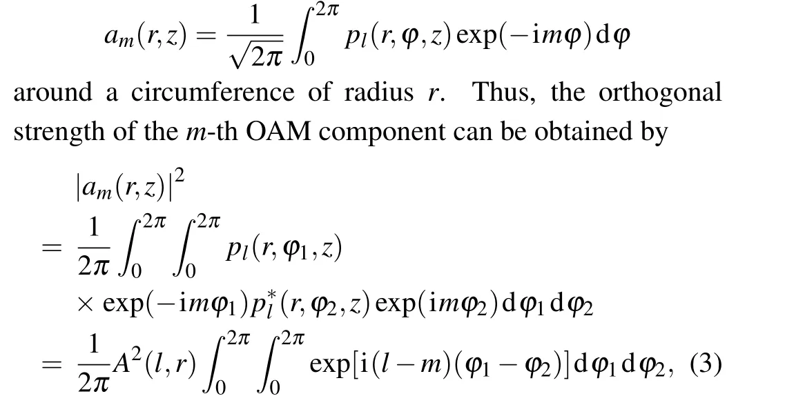
whereA(l,r) is the radial pressure distribution of the single-OAM beam of orderl, andpl(r,ϕ1,z) andp∗l(r,ϕ2,z) are the pressures at different azimuthal angles around the circumference. Thus, the spiral harmonic power of them-th OAM can be calculated byCm=∫∞0|am(r,z)|2rdr. For the ring-array ofMreceivers used in this study,the spiral harmonic power can be discretized to
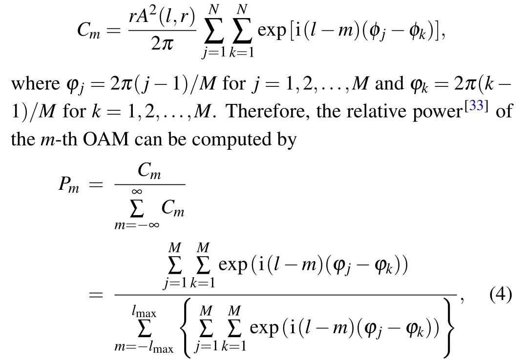
wherem= 0,±1,±2,±3,...,±lmaxrepresents the possible OAM orders included. For an OAM-multiplexed beam of orderl,the case ofPm=1 occurs only form=lwith a non-zeroCm,[34]indicating that the included OAMs can be decoded by OAM spectrum decomposition.
上海市节能协会秘书长徐君专题演讲中,在分析上海市区域性能源应用现状基础上,重点介绍了工业园区智慧能源微网、智慧能源平台及虹桥商务区能源微网的构想,并就推动上海区域性能源综合利用提出发展路径及政策建议。
3. OAM spectrum dispersion in beam misalignment
The accuracy of OAM decoding of AV beams is affected not only by the signal-to-noise ratio (SNR) of the acoustic transmission, but also by the relative position and attitude of the transceiver arrays. OAM communication based on the orthogonality depends on the cross-sectional distributions of AV beams, which are sensitive[35]to the circular distribution of pressure and phase. With respect to the ideal reception condition of coaxial transceiver arrays placed in parallel,variations of pressure and phase are produced by the translation or deflection of the receiver array,resulting in a decreasing accuracy of OAM decoding. Therefore,beam alignments by adjusting the transceiver arrays is crucial for OAM communication via AV beams.
Given ideal reception and perfect beam alignment with parallel, coaxially arranged transceiver arrays, OAM spectra of the single-OAM and OAM-multiplexed beams in the transverse plane atz=25 cm are simulated forN=16,M=16 andr=5 cm with the OAM varying from−7 to 7. The OAM spectrum plotted in Fig. 2(a) for the single-OAM beam withl=1 has a clear OAM bar ofPm=1 only form=1. While two OAM bars with the samePmof 0.5 are clearly observed in Fig. 2(b) for the OAM-multiplexed beam withl=1 and 2. Moreover, three OAM bars with the samePmof 0.33 can also be identified in Fig.2(c)for the OAM-multiplexed beam withl=1, 2, and 3. The OAM spectra of OAM-multiplexed beams in Fig. 2 demonstrate that, the same powerPm=1/Scan be created for all included OAMs under ideal reception conditions without OAM dispersion.
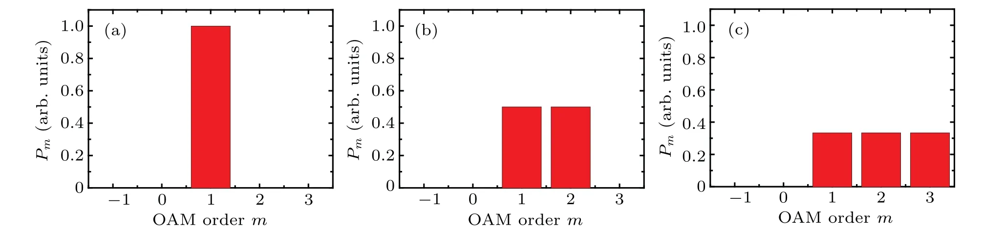
Fig.2. OAM spectra of(a)the single-OAM beam with l=1,and the OAM-multiplexed AV beams with(b)l=1 and 2,and(c)l=1,2,and 3,under the ideal reception condition of perfectly aligned acoustic beams.
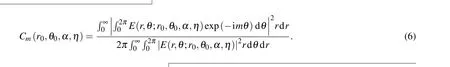
For the OAM-based communication via AV beams, two types of misalignments[36]are possible in practical applications. The first type consists of the center translation in thexyplane for transceiver arrays placed in parallel,and the second type is the angular deflection around the center of the receiver array. In the previous studies of optic-vortex communications,the combined effects of the lateral (shift or translation) and tilt (angular deflection) displacements of a misaligned laser beam on the OAM spectrum were analyzed theoretically and experimentally.[23,37,38]Experienced a misalignment simultaneously by shift and tilt, the transformation of a Gaussian beam is in the form of
wherer0andθ0are used to describe the lateral displacement in polar coordinates,andαandηare the tilt parameters of the angular deflection.kis the wave number andω0is the waist of the Gaussian beam. Based on the principle of OAM spectrum decomposition,the weight of them-th OAM becomes
By further definingu0= 2r0/ω0,v0=kω0sinαandβ=θ0−η,an analytical expression of the weight can be achieved
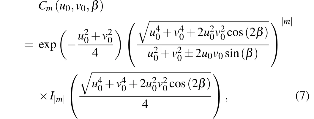
whereIm(x) is them-th modified Bessel function of the first kind.
It is clear that, great changes of intensity and phase can be produced by the misaligned Gaussian beam that has experienced shift and tilt. Varied with the three misalignment parametersu0,v0andβ, the weight allocated to the OAM state increases from zero to a maximum value, and then declines as the misalignment increases,which provides the theoretical evidence for the OAM dispersion of optical beams. Similar to optic-vortex beams,obvious misalignments of AV beams can be produced by the lateral and tilt displacements of the receiver array.Whereas,for AV beams generated by the acoustic superposition of a ring-array in diffraction mode,the acoustic field is different from the ideal Bessel or Gaussian beam and cannot be described accurately by a mathematical formula. The OAM dispersion can be demonstrated by numerical simulations, although the accurate derivation and analysis in theory is difficult to achieve.
Keeping the same simulation parameters as above, we simulate OAM spectra of the single-OAM beam withl=1 for the transceiver arrays with the translation distances ofd=1 and 3 mm[see Figs.3(a)and 3(b)]. Compared with the OAM spectrum in Fig. 2(a),P1decreases with the increase of the translation distance, and obvious dispersion appears around OAMs withm=−1, 0, 2, and 3. The OAM spectrum ofPmis symmetric aboutm=1, with the sum of the OAMs giving unity(1). Meanwhile,a similar symmetric distribution of the OAM spectrum for the array deflection ofγ=2◦is also displayed in Fig. 3(c). In addition, for the transceiver arrays with the translation distanced=5 mm and the deflection angleγ=2◦,the OAM spectrum of the single-OAM beam withl=1 shown in Fig. 3(d) reveals serious OAM dispersion with an asymmetric distribution of surrounding OAMs.[39]The OAM spectrum ofPmform=1 is reduced to 0.4 and the OAM dispersion appears clearly form=−1, 0, 2, and 3. The clear OAM dispersion for acoustic beams misaligned by array translation and deflection is consistent with the results from optics,lending further support to the theory of OAM spectrum decomposition. Therefore,the accuracy of OAM-based acoustic communication depends strongly on the beam alignment with respect to transceiver arrays.[37]
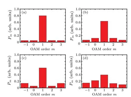
Fig. 3. OAM spectra of the single-OAM AV beam of l =1 with the translation and deflection of the transceiver arrays of(a)d=1 mm and γ =0◦, (b) d =3 mm and γ =0◦, (c) d =0 mm and γ =2◦, and (d)d=5 mm and γ =2◦.
4. Beam alignments based on SD-OAM
wherePmandP′mare relative powers of the OAM of ordermunder ideal and non-ideal receptions, respectively, andKis the total number of OAMs included in the OAM-multiplexed beam.
To evaluate the sensitivity of the SD-OAM,a single-OAM beam withl=1 is selected to simulate array misalignment.Firstly,by fixing transceiver arrays in parallel and moving the receiver array in thexdirection, acoustic pressures detected by the receiver array are used to analyze how the translation distance affects the OAM dispersion. The SD-OAM distribution in Fig. 4(a) shows a monotonic increase with respect to the translation distance. Then, by rotating the receiver array around its center,the SD-OAM distribution in Fig.4(b)shows a monotonous rise with the increasing deflection angle. These results indicate that the SD-OAM can serve as a sensitive indicator to evaluate the effect of beam alignment,with the minimum of zero achieved only when the transceiver arrays are coaxial and parallel.
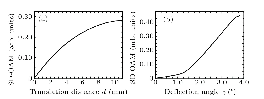
Fig. 4. Distributions of the SD-OAM with respect to (a) the translation distance and (b) the deflection angle of transceiver arrays for the single-OAM beam with l=1.
To combine the translation and deflection of transceiver arrays, two beam alignment methods are developed, and the corresponding schematic maps of the single-array translation alignment and the dual-array deflection alignment are presented in Figs.5(a)and 5(b),withdbeing the translation distance,andγandθbeing the deflection angles of the receiver and transmitter arrays in thexzplane,respectively. As shown in Fig. 5(a), the single-array translation alignment can be realized by the two-dimensional(2D)movements in thexandydirections and adjustments of the deflection angle in theγdirection of the receiver array without adjusting the source array.This strategy can be applied to passive cases in which only the receiver array can be adjusted. For the dual-array deflection alignment shown in Fig.5(b),the beam axes of the transceiver arrays are angularly separated by an angleθ. The transmitter array may firstly be rotated to diminish the deflection angle until it is perpendicular tooz′.Next,the deflection alignment can be further tuned by rotating the receiver array toγ=0◦. The dual-array deflection alignment implemented by adjusting the angles can be applied in most practical applications in which transceiver arrays can be adjusted, and is especially suitable for active cases of wide-range beam alignments.
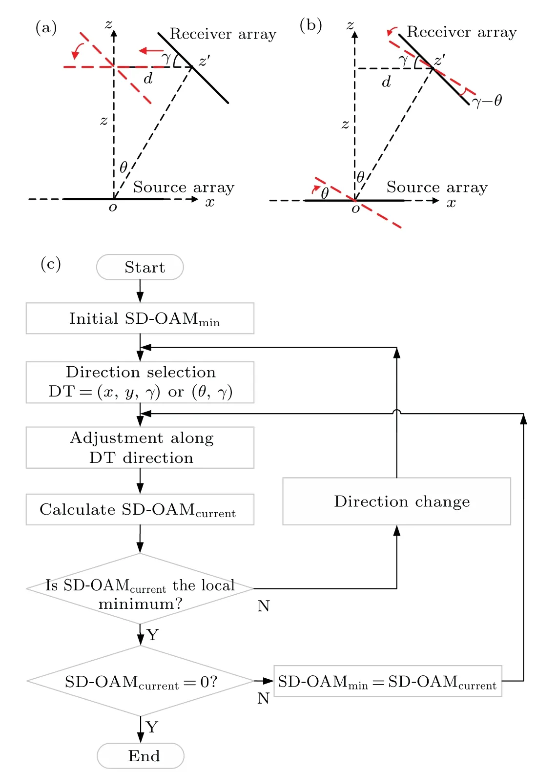
Fig.5.Schematic maps of(a)the single-array translation alignment and(b)the dual-array deflection alignment,and(c)the corresponding flow chart of beam alignments along each adjustment direction based on the least SD-OAM.
To attain perfect beam alignment,a general flow chart of the two methods based on minimizing the SD-OAM is presented in Fig. 5(c). Initially, the SD-OAM at the initial position is set as the minimum value (SD-OAMmin). Next, continuous adjustments along each direction (DT=x,y,γorθ)can be conducted to decrease the SD-OAM(SD-OAMcurrent),otherwise, a new round of adjustments starts along the next direction. After several rounds of adjustments along the(x,yandγ)or(θandγ)directions,perfect beam alignment can be realized with SD-OAMmin=0. By applying the ring-arrays of 16 sources and 16 receivers, the OAM spectrum and the corresponding SD-OAM are calculated for a single-OAM beam withl=1. Corresponding to the coaxial transceiver arrays placed in parallel, the center of the receiver array is initially supposed to be at (8 mm, 8 mm) with a deflection angle ofθ=3◦. The detailed adjustments with the corresponding SDOAMs at all steps are then obtained for the two alignment methods.
Figure 6(a)shows the SD-OAM as a function of the translation of the receiver array along thexandydirections and the rotation byγbased on the single-array alignment strategy.The acoustic pressures of the ring-array were recorded to calculate the SD-OAM for each adjustment.As shown in part I of Fig.6(a),the receiver array is adjusted along the+xdirection at the step of 1 mm. If a step in the+xdirection decreases the SD-OAM,the next step continues in the+xdirection. Otherwise,if the result is an increase in the SD-OAM(i.e.,at point A), the receiver array must be stepped back to the previous position and then stepped in the−xdirection. After the ten steps in the−xdirection,the SD-OAM increases at point B,so the receiver array should be stepped back in the+xdirection.Given that the SD-OAM does not reach zero, the adjustment in thexdirection is terminated and the next adjustment starts in theydirection. As shown in part II of Fig.6(a),the receiver array is stepped at increments of 1 mm in the +ydirection until the SD-OAM increases again (at point C). The receiver array steps along the−ydirection to decrease the SD-OAM.After five steps,the adjustment in theydirection stops because the SD-OAM increases(at point D).In part III,the angle adjustment in the +γdirection is done at the step of 0.5◦until the SD-OAM increases(at point E)and then the opposite rotation is done in the−γdirection. After seven angular steps,the SD-OAM increases at point F,meaning that a new alignment direction should be adopted.
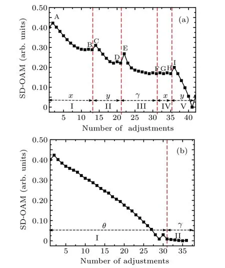
Fig. 6. Adjustment processes based on (a) the single-array translation alignment and(b)the dual-array deflection alignment.
Because the SD-OAM does not reach zero after the first round of adjustments in thex,y, andγdirections, a second round of adjustments starts. Parts IV and V of Fig.6(a)plots the adjustments of the receiver array in thexandydirections with the SD-OAM increasing at points G, H, and I. After 41 steps,the minimal SD-OAM of zero is attained.An increase in the SD-OAM upon further adjustment in an arbitrary direction means that the beam is perfectly aligned with the transceiver arrays. For the single-array translation alignment,only the receiver array is adjusted,whereas the transmitter array is fixed.The alignment process is intuitive and accurate, and involves multiple rounds of adjustments in three directions.
According to the basic idea of the dual-array deflection alignment, the line between the centers of the transceiver arrays can be treated as the beam axis, and the beam alignment can be done by only adjusting the deflection angle of the transceiver arrays. According to the initial position of the arrays,the total angle adjustments ofθ=atan(d/z)=2.6◦andγ −θ=0.4◦for the transceiver arrays should be done in angular steps of 0.1◦. With the center of the transmitter array fixed,the deflection angle of the transmitter array is adjusted. Part I of Fig.6(b)plots the SD-OAM as a function of the number of steps in deflection angle. The SD-OAM increases at point A after stepping in the +θdirection, so the opposite adjustment is adopted after stepping back in the previous position.Continuous steps in the−θdirection cause the SD-OAM to decrease monotonically until point B,at which point the transducer array has been over adjusted. We therefore take one step back. In part II of Fig. 6(b), we fix the center of the receiver array and adjust the deflection angle in the+γdirection. The increase in the SD-OAM at point C means that we should step in the opposite direction(−γ). Upon further adjusting the deflection angle of the receiver array, the SD-OAM decreases until reaching zero at point D,whereupon the beam alignment is complete. Given that translation adjustments of the receiver array can be converted to adjustments of the deflection angle of the transmitter array, the dual-array deflection alignment can be applied to rapidly adjust transceiver arrays in a wide range of applications.
5. Experimental measurements
To verify the validity of the proposed beam alignment methods based on the SD-OAM, an experimental system[20]consisting of a single-ring transmitter array was constructed to generate an AV beam. The source array was composed of 16 transducers with the radius of 2 mm at the center frequency of 40 kHz,and were fixed around a circumference(radius 5 cm) on an acrylic plate. Driving the transducers with 16 phased sinusoidal signals with a phase difference ofπ/8 between each transducer,the AV beam withl=1 was generated in air. An ultrasonic transducer was used as receiver to detect the acoustic pressure at each position. Controlled by a motion controller,2D scanning measurements of the acoustic fields were conducted by using two stepper motors.The waveform of the acoustic pressure at each position was collected by a digital oscilloscope for further calculation of the OAM spectrum.
The cross sectional distributions of pressure and phase for the AV beam withl=1 atz=25 cm are measured as plotted in Figs.7(a1)and 7(b1),and the corresponding numerical results are also presented in Figs. 7(a2) and 7(b2) for comparison. The experimental maps consist well with the simulations in terms of the pressure ring and phase spiral, demonstrating the OAM of the AV beam. By sampling 16 acoustic pressures evenly on the circumference withr=5 cm andd=0, the experimental OAM spectrum of the single-OAM beam withl=1 is calculated as shown in Fig. 7(c). A clear OAM bar of 0.8 appears form=1, and the asymmetric distribution of the OAM dispersion form=−1,0,2 and 3 remains,leading to an increased SD-OAM.Then,by translating the circumference away from the beam axis at the step of 2 mm,16 acoustic pressures on the ring are sampled at each step to calculate the SD-OAM. The experimental distribution of the SD-OAM as a function of the translation distance is plotted in Fig. 7(d)(dashed line), and the corresponding numerical curve (solid line) is also provided for comparison. Both numerical and experimental results show that the SD-OAM increases with increasing misalignment of the transceiver arrays. Note that,the experimental SD-OAM is greater than the numerical one,which might be due to the more serious OAM dispersion introduced by possible measurement errors or by the noise level.
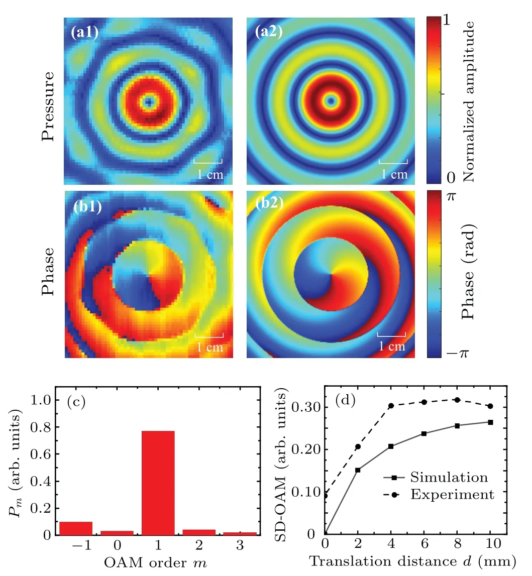
Fig. 7. (a) Experimental and (b) numerical cross sections of pressure and phase for the single-OAM AV beam with l=1 at z=25 cm,(c)the OAM spectrum of the experimental acoustic field with r=5 cm and d =0, and(d)the corresponding translation distance dependence of the SD-OAM.
6. Discussion
It was proved by Anzolinet al.that, with the off-axis displacement of the input light beam, an asymmetry intensity pattern could be produced in the far-field with two different peaks along the direction of the maximum asymmetry.The relationship between their ratio and the off-axis displacement might be used to align the beam.[4]With the variation of the topological charge for different reference axes,the axis tilt of a light beam could be identified by using a charge coupled device(CCD)camera.[23]To ensure the precise alignment of transceiver arrays in high-speed visible light communications, an effective scheme of auto-alignment and tracking of transceivers was proposed with a high-speed camera serving to locate of the target light source and a two-axis gimbal serving for the initial alignments between transceivers. Good flexibility and effectiveness of the proposed scheme provided a high spatial efficiency and a low cabling complexity in data centers by image processing.[41]However,beam alignment based on image processing is not easy to implement for underwater acoustic communications because of the large amount of time required to acquire the complex data. In the current study,only a small number(16)of detectors are required to precisely align the beam based on the least SD-OAM,which makes this strategy use a simplified structure applicable in practical applications.
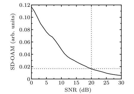
Fig.8. SNR dependence of the SD-OAM for the perfectly aligned AV beam with l=1.
To investigate how the noise level affects the SD-OAM for AV beams,Gaussian white noise at different SNRs was introduced to the acoustic field to simulate the cross-sectional distributions of pressure and phase atz=25 cm for the perfectly aligned AV beam withl=1. Figure 8 shows that the SD-OAM as a function of the intensity of the noise level decreases with the increase of SNR.For example,the SD-OAM decreases from 0.116 to 0.016 as the SNR increases from 0 to 20 dB.Thus,the accurate zero of the minimal SD-OAM is difficult to obtain in the presence of noise. Moreover, the accuracy of beam alignment is also influenced by stepping along the(x,y,γ)or(θ,γ)directions because of the nonzero value of the minimal SD-OAM.For an initial position of the receiver array at(8,8)mm in the current study,precise movements to(0,0)can be realized by making fixed steps of 1 mm in thexandydirections. However,for an actual offset of a noninteger multiple of the step, the alignment process cannot stop without reaching a minimal SD-OAM of zero.Therefore,for highprecision applications of beam alignments,the step-variant adjustment should be applied to further reduce the minimal SDOAM, and a stable approximation of the minimal SD-OAM should be used to optimize the beam alignment.
In addition, the accuracy and reliability of OAM decoding is very sensitive to the radial deviation and the angular deflection of transceiver arrays, and the quality of data transmission is significantly reduced by small misalignments.[26,27]The perfect alignment of transceiver arrays is the most direct and effective method to guarantee the channel capacity and the accuracy of AV communications. To circumvent the large performance degradation, a transmit-receive beam-steering approach was proposed in the case of misalignment[27]that involves calculating the phase difference between a reference element and them-th element of the uniform circular receiver array,and this phase difference can be used to adjust the original phases at the phase shifters of the receiver array. The mathematical analysis strongly reduces but does not eliminates the effect of the radial deviation and angular deflection.Therefore, compared with previous approaches, the proposed method based on the minimal SD-OAM is simple and direct and does not require multiple pre-measurements of single-OAM AV beams,making it a feasible method for applications in acoustic communications.
7. Conclusion
The conditions for ideal reception of data communicated by AV beams were constructed by aligning transceiver arrays with respect to the AV beam and using OAM spectral decomposition to guide the alignment. A theoretical model of OAM spectrum decomposition is proposed for single-ring transceiver arrays. Based on numerical simulations and experimental measurements, the SD-OAM is shown to increase with the translation distance or angular deflection of beam misalignments due to the increased OAM dispersion. Furthermore,two alignment methods are developed based on the least SD-OAM, with each certified by multiple array translations and deflections in three dimensions by using single-ring arrays of 16 transmitters and 16 receivers. The results provide theoretical and technical support to the rapid beam alignment for underwater acoustic communications.
Acknowledgements
The authors would like to thank Ruijie Cao for his experimental measurements and data processing in paper revision.
Project supported by the National Natural Science Foundation of China (Grant Nos. 11934009, 11974187, and 12174198).
猜你喜欢
中小学校长(2021年7期)2021-08-21 06:49:52
学生导报·初中版(2020年1期)2020-05-03 10:07:57
成都信息工程大学学报(2017年4期)2018-01-22 02:08:24
车迷(2017年12期)2018-01-18 02:16:12
中国商界(2017年4期)2017-05-17 04:35:57
新闻传播(2016年23期)2016-10-18 00:54:07
通信电源技术(2016年6期)2016-04-20 06:21:15
制冷技术(2016年6期)2016-03-08 11:07:48
电测与仪表(2015年16期)2015-04-12 00:44:34
中国当代医药(2015年16期)2015-03-01 02:03:15

- Chinese Physics B的其它文章
- Fault-tolerant finite-time dynamical consensus of double-integrator multi-agent systems with partial agents subject to synchronous self-sensing function failure
- Nano Ag-enhanced photoelectric conversion efficiency in all-inorganic,hole-transporting-layer-free CsPbIBr2 perovskite solar cells
- Low-voltage soft robots based on carbon nanotube/polymer electrothermal composites
- Parkinsonian oscillations and their suppression by closed-loop deep brain stimulation based on fuzzy concept
- Temperature dependence of spin pumping in YIG/NiO(x)/W multilayer
- Interface effect on superlattice quality and optical properties of InAs/GaSb type-II superlattices grown by molecular beam epitaxy