A Robotic Teleoperation System for Precise Robotic Manipulation by Human-Machine Interaction
2022-12-17 02:59:12SUNFuchunGUODiCHENYang
上海航天 2022年4期
SUN Fuchun, GUO Di, CHEN Yang
A Robotic Teleoperation System for Precise Robotic Manipulation by Human-Machine Interaction
SUNFuchun, GUODi, CHENYang
(Department of Computer Science and Technology, Tsinghua University, Beijing 100084, China)
Teleoperation is of great importance in the area of robotics, especially when people are unavailable in the robot workshop. It provides a way for people to control robots remotely using human intelligence. In this paper, a robotic teleoperation system for precise robotic manipulation is established. The data glove and the 7-degrees of freedom (DOFs) force feedback controller are used for the remote control interaction. The control system and the monitor system are designed for the remote precise manipulation. The monitor system contains an image acquisition system and a human-machine interaction module, and aims to simulate and detect the robot running state. Besides,a visual object tracking algorithm is developed to estimate the states of the dynamic system from noisy observations. The established robotic teleoperation systemis applied to a series of experiments, and high-precision results are obtained, showing the effectiveness of the physical system.
teleoperation; human-machine interaction; precise manipulation; visual object tracking; robotich and manipulation
0 Introduction
The robotic teleoperation indicates that a robot is controlled remotely by a human operator. It is very useful in the situations where people are unavailable in the workspace. It provides a way to employ the human intelligence in the robot control at a distance, and has already been applied in many fields as an important human-machine interaction means. In the aerospace field, it is supposed to replace astronauts in some dangerous missions, e.g., the space rover[1]used to explore outer space is envisioned to to be controlled both autonomously and by teleoperation. A new gesture- and speech-guided teleoperation method is proposed to achieve a more immersive and natural interaction environment[2]. Recently, the concept of telemedicine has attracted people’s interest. In fact, surgical robots such as the Da Vinci robot have already allowed doctors to operate remotely on patients. It is promising that the robotic teleoperation will play a significant role in boarder areas.
In the robotic teleoperation, the robot accepts instructions from the human operator at a distance through some sensors or control mechanism through a communicating network[3], and sends its status and environment information to the human operator. Only the efficient interaction between the robot and human operator can make the robotic teleoperation system performs well. There are a variety of human-machine interfaces for the robotic teleoperation system. Wearable devices such as data gloves and helmets are commonly used in the teleoperation system. HU et al.[4]proposed an hand-arm teleoperation system, in which a data glove was used to control the movement of the dexterous hand and a stereo helmet was adopted to display the collected visual images. Recently, the haptic feedback teleoperation system[5-6]is increasingly popular. With the force/tactile feedback provided by the haptic device, the operator can control the robot more precisely and flexibly. It can even be used for some delicate surgeries to locate tumors[7]. Besides the contacting interfaces, KOFMAN et al.[8]proposed a vision-based human-machine interface to locate and orientate the end-effector of the robot.
With the development of sensing technology,multimodal sensing information has been widely used in the robotic teleoperation system, owing to its advantage in precise operations from the remote site. However, in some complicated situations, especially when the robot is moving, visual information is still the most intuitive way for the human operator to get to know the situation of the remote site and implement teleoperation. Therefore, visual feedback is used in almost all teleoperation systems. Usually, global cameras and local cameras are used to monitor the robot workspace. The global cameras are responsible for displaying the environment information of the whole workspace, while the local cameras are in charge of tracking the end-effector of the robot and reflecting the detailed manipulation information to the human operator timely. In view of this, a reliable visual tracking algorithm is necessary for the robotic teleoperation system.
Visual trackinghas applications in numerous fields[9-11], e.g., behavior analysis, robotics, and industrial monitoring. In a robotic teleoperation system, the end-effector of the robot is always tracked, so that the human operator can fulfill the remote operationtimely. Particle filter is a popular way for visual object tracking[12]. It can estimate the current hidden state of the object with available and history observationdata.
Remote manipulation is an important approach for robotic operation. It not only can help robots to compensate for the lack of autonomy,but also can work in the environment where people cannot arrive.In this paper, a robotic teleoperation system with a user-friendly interfaceis introduced, and a visual object tracking algorithm with a structured linear coding strategy is used to assist the human operator to track the end-effector of the robot timely. In the robotic teleoperation system,the data glove and the7-degrees of freedom (DOFs) force feedback controller are used for the remote control interaction, and the control system and the monitor system are designed for the remote elaborate manipulation.With the proposed robotic teleoperation system, some basic operations, e.g., grasping and placing objects and positioning and orientationing the end-effector of the robot, are simulated, and a series of tasks, e.g., to insert/extract, replace, and catch objects, are implemented. The obtained results verify the effectiveness of the physical system.
1 System framework
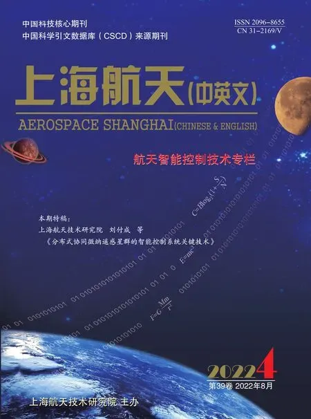
The robotic teleoperation system introduced in this paper is composed of two sub-systems, i.e., the monitor system and the control system (see Fig. 1).
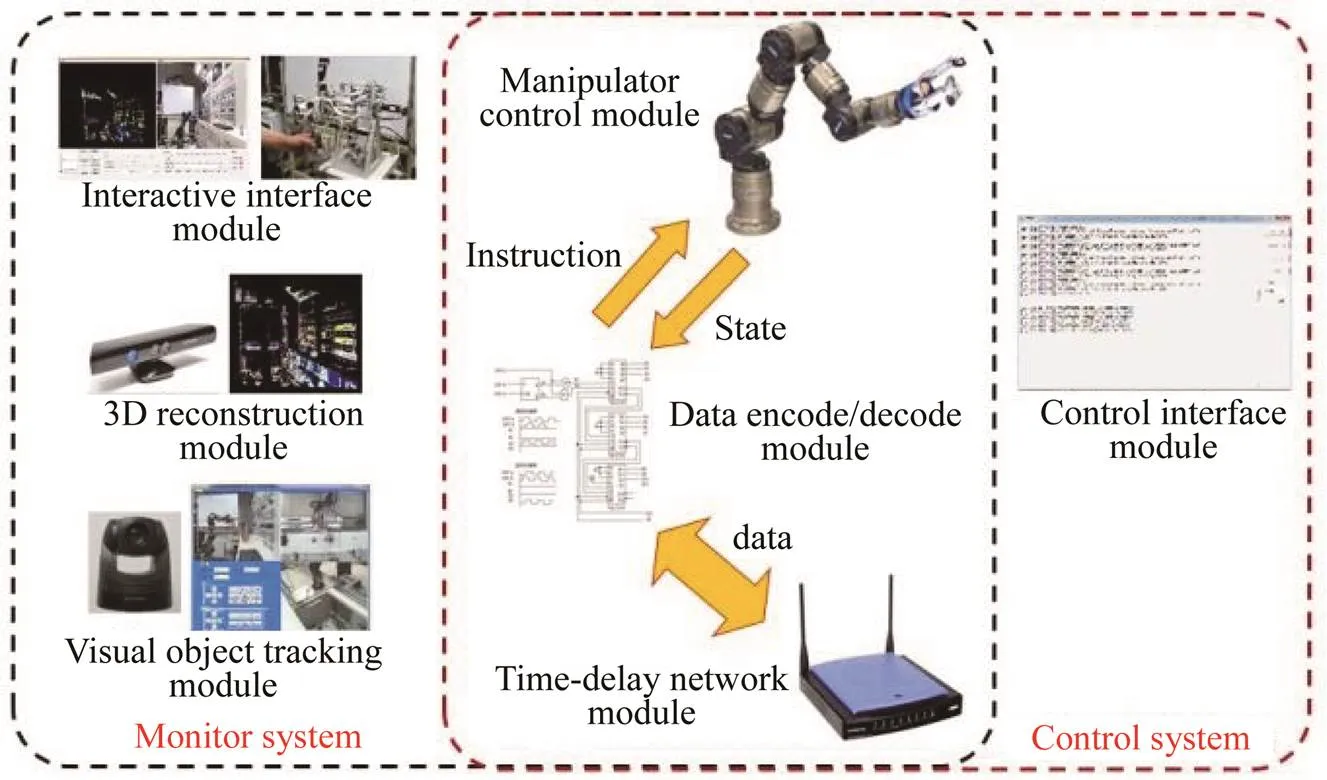
Fig. 1 Module diagram of the robotic teleoperation system
The monitor system communicates with the robotic operating platform. It receives the state information of the robot, acquires the image information of the workspace, and processes the acquired data. Meanwhile, it also receives and encodes the information from the operator, and sends the encoded information to the control system to process. It is a real-time interactive system, and is mainly responsible for the integrating and processing of multiple data sources in a structured way.
The control system receives instructions throughout the network. It can remotely control the robot to implement assigned tasks. The human operator can also use the interface module to debug the system. When the data encode/decode module sends out instructions, the operation of the manipulator will be activated. At the same time, the states of the robot will be sent to the monitor system.
1.1 Hardware
The hardware of the robotic teleoperation system includes a robot as well as its working platform, an image acquisition device, a multi-freedom controller, a data glove, and computers. One of the contributions of our system is that we develop a novel data glove to control the motion of the robotic hand, which makes the control of the hand more precise and flexible.
1) Remote side robot
The robot used on the remote side is the core of the teleoperation system. The robot we use consists of a 7-DOFs manipulator (see Fig. 2(a)) and a 4-DOFs dexterous robotic hand (see Fig. 2(b)). The modular manipulator is produced by SCHUNK with 7 force-torque modules. It can rotate around its axis. The manipulator is fixed on a slide rail, allowing a translation movement. The robotic hand utilized is the Barrett band. It is a simple three-fingered mechanical hand with 4-DOFs. The hand can grasp objects of different shapes and sizes. With the pressure sensors on its fingers and palm (see the blue area of the fingers and palm in Fig. 2(b)), the hand can also provide detailed real-time grasping tactile data.
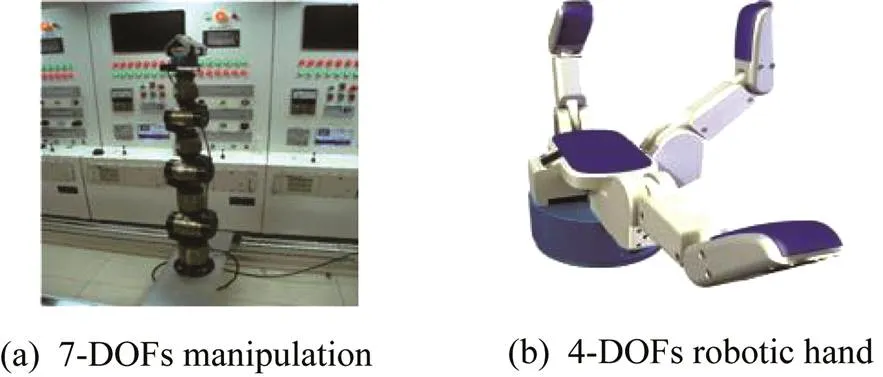
Fig. 2Manipulator and robotic hand used in the experiment
2) Image acquisition device
The image acquisition device consists of the Pan/Tilt/Zoom(PTZ) cloud cameras (see Fig. 3) and the Kinect camera. The PTZ cloud cameras are able to rotate and zoom in and out greatly, and thuscan track the object and the workspace of the robot from all angles clearly. It is particularly suitable for capturing the details of the local images. The Kinect camera can provide both RGB and depth images simultaneously, and is utilized to assist the human operator to monitor the whole working environment.

Fig. 3 Layout of the PTZ cloud cameras in the working environment
3) Data glove
A new-type data glove is developed to control the robotic hand for precise manipulation. It utilizes the inertial sensor and magnetic sensors to estimate each angle of the finger joints, and thus can accurately measure the orientations. A system-in-package (SiP) technique is used, and a 3-axis gyroscope, a 3-axis accelerometer, and a 3-axis magneto-meter are integrated into a 3 mm×3 mm×1 mm package. The package is then mounted on a solid printed circuit board (PCB) with the dimensions of 10.0 mm×15.0 mm×2.6 mm, which is small enough for the data glove. The data glove is designed based on a 20-DOFs human hand model (see Fig. 4), and thus can provide enough flexibility and dexterity to control a robotic hand for precise manipulation. Each joint of the human hand model has a corresponding SiP sensor in the data glove. The human operator can wear the data glove to control the motion of the robotic hand on the remote side, which is useful in precise manipulation.
4) Other harware
The computers are used for the robot control system and monitor system, and the a multi-freedom controller is used by the operator to perform remote operations on the manipulator. All of the computers used are ordinary personal computers (PCs) bought from the consumer market. The controller for remote operation is a 7-DOF force feedback controller developed by the Southeast University (see Fig. 5).

Fig. 4 Data glove and human hand model
Fig. 5 7-DOFs force feedback controller
1.2 Control System
The working procedure of the control system is as follows. First, the instructions are got from the time-delay network, and are decoded by the data encode/decode module. Second, the manipulator control module is activated for operation, while another thread of the control system is actived to monitor the state data of the robot at the same time. With the state data and the manipulator control module, the pose of the robot can be obtained. Third, the state information are encoded by the data encode/decode module and sent back to the monitor system through the time-delay network module.Finally, the operation user interfaces are used to debug the system. The data encode/decode module encodes the state and instruction information into data units with a fixed length, and decodes the data units back to the states or instructions at the server. The state information mainly includes the positions and joint angles of the manipulator and dexterous hand. The commands include all possible operations, such as to initialize, stop, move to assigned joint angles, and move to an assigned position. The manipulator control module and the time-delay network module are described in details in the following subsections.
1.2.1Manipulator control module
The manipulator control module is shared by both the control system and the monitor system. In the control system, the manipulator control module is responsible for the actual operations of the manipulator and the dexterous hand in the workspace. In the monitor system, it is used to simulate the control of the manipulator. Given one control instruction, it can calculate the pose of the manipulator in a simulated environment so that the operator can check the reachability and security of the instruction. Only reachable and secure instructions can be sent to the control system for real operations.
The manipulator control module provides velocity control and position control. The velocity control reads the position and velocity information of the motorfrom the control panel, and converts the obtained information to the pose of the manipulator. The pose information is then transmitted to the manipulator. The position control controls the motion of the manipulator directly. With the position determined, the path planning method is used to calculate the trajectory of the manipulator. The instructions are then sent to each joint of the manipulator. In practice, in terms of the large time-delay in the robotic teleoperation system, we normally use the position control to control the end of the manipulator to a desired position.
The most important part of the position control is the path planning algorithm. The path planning used in our system is with straight lines. Given an assigned position for the end-effector of the manipulator, the algorithm will give a joint angle sequence for the manipulator to enable the manipulator to move from its current position to the assigned position in a line trajectory as far as possible. This joint angle sequence is actually a piecewise interpretion of the manipulator trajectory. In order to make the moving of the end-effector of the manipulator approximate a line path, the algorithm divides the trajectory into several equal line parts. In each line part, the joint angles are calculated so as to obtain the target position. Since each part of the trajectory is of the same length, the instruction sequence is an equal interval sequence.
The dexterous hand control is also in the manipulator control module. It is relatively easier to be controlled by simply opening or closing the hand. The whole set of the robot in our teleoperation system can be used to grasp objects of different shapes and materials.
1.2.2Time-delay network module
The time-delay network module is used to simulate the time delay among the communication of each system. A one-way transmission control protocol (TCP) connection is established for each data channel, where the client sends data to the server. For the manipulator control module, it interacts with the monitor system in a two-way communication, sending the state information of the robot and receiving the operation instructions. Therefore,two TCP connections are needed to be established. For the monitor system, besides the two connections with the manipulator control module, three more connections are needed to connect the image acquisition system. Two server connections are used to receive the local monitoring images from the PTZ cloud cameras and the global three-dimensional (3D) point cloud information from the Kinect camera, and one client connection is used to send the visual object tracking instructions to the PTZ cloud cameras.
The time delay of the network is achieved by using a message buffered queue with a timer on the server side. In normal situations, as long as the connection is established between the server and the client, the server will continuously read the messages sent by the client from the buffer. In order to make the time delay of the network, messages will not be fed to the system immediately, but will be stored in a message queue with time stamps. When the system reads the message from this queue, the time stamps will be checked from the head to the end. The last message with the saving time no less than the set delay time will be read out, and all the messages outdated will be removed. Only messages satisfing the time delay requirement will be returned. Thus, all the messages received have been time delayed, and the satisfied time delayed messages are returned to the system for further processing.
To make the implementation easier, set the length of all the robot states and instruction messages as 256 bytes. The server reads a fixed number of bytes messages from the buffer, and then puts the message unit into the message queue. The length of the queue is fixed to save memory space. When the queue is full, the messages at the head of the queue will be abandoned. When there are messages getting into and popping out of the queue, the time stamps of the head message will be checked to confirm that the message is not outdated. The time-delay network of the client is relatively easier. All of the messages on the server side will be time delayed, and thus there is no time delay on the client side of the network.
1.3 Monitor system
The monitor system is an interactive system that can integrate and process multiple sources of data in a structured way. There are some modules in the monitor system similar to modules in the control system. The monitor system includes a 3D reconstruction module, a visual object tracking module, and an interactive interface module. Among these modules, the 3D reconstruction module together with visual object tracking module constitutes an image acquisition system, which is very important for the monitor system.
1.3.1Image acquisition system
In the image acquisition system, the Kinect camera can provide the operator with the global image of the workspace, and the PTZ cloud cameras are used to capture the local images and implement visual object tracking.
With the global image provided by the Kinect camera, the operator can master a general situation of the workspace and conduct general operations such as moving the manipulator to an approximate position. Because the general operation does not care much about the details, the low resolution of the Kinect camera will not affect the operation. With the depth information provided by the Kinect camera,the operator can obtain the 3D structure of the experiment scenario, and thus has a more realistic perception for the operation situation. A 3D reconstruction image and a RGB image given by the Kinect camera are shown in Fig. 6. It is clear that the images are basically cover the whole robotic workspace. The 3D reconstruction image can help the operator to better predict the relative position between the manipulator and the target object.

Fig. 6 Images provided by the Kinect camera
The 3D reconstruction of the scenario is generated by the RGB image and its corresponding depth image. We firstly calibrate the optical camera and the depth camera (the Kinect camera) to obtain the geometry relationship of them, and then find the pixel of the depth image and the pixel RGB value of the corresponding RGB image. By means of the depth value and the internal matrix of the camera, we can obtain a 3D point cloud of the scenario with color information. Because the resolution of the Kinect camera is relatively low, the depth values of some pixels are invalid, and the displayed point cloud is sparse. However,the operator is still able to recognize the relationships between different objects in the scenario.
The PTZ cloud cameras in the image acquisition system are responsible for capturing more detailed image information. For some precise robotic manipulations, it is necessary to observe the object and the end-effector of the manipulator closely so that the manipulations can meet the precision requirements. The PTZ cloud cameras have the characteristics of rotating and zooming in/out flexibly, and can provide the desired image information. A visual object tracking algorithm is also applied in the image acquisition system. It can track the end-effector of the manipulator at any time and help the operator to monitor the operations of the manipulator.
The diagram of a PTZ image capturing system is shown in Fig. 7. The PTZ cloud cameras send the acquired images to the operators to specify the target object, and then the monitor system tracks the target object by a visual object tracking algorithm. The interface of the PTZ sampling system is shown in Fig. 8. It can be drawn that the PTZ cloud cameras can capture the details of the scenario, which is very useful for the precise manipulation. In the upper row of Fig. 8, the red rectangle is the tracking box. It is specified in the initial frame by the operator, and then the box will track the movement of the target object autonomously by means of the proposed particle filter object tracking algorithm. In this way, the operators can manipulate the object properly.
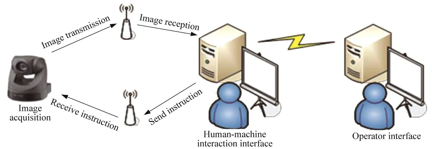
Fig. 7 Diagram of the PTZ image capturing system

Fig. 8 PTZ sampling system interface
1.3.2Human-machine interaction module
The human-machine interaction module is one of the most important parts of the monitor system. The operator not only needs to monitor a lot of information of the workspace including the scene image, the robot states, etc., but also needs to send a variety of instructions to the robot by means of the monitor system. Therefore, the interface of the human-machine interaction module becomes very complex. Although the operator can use the multi-freedom controller (see Fig. 5) to give instructions to the robot, for simplicity, most instructions are given by a traditional userinterface (UI). The human-machine interaction interface consists of three panels, i.e., controller panel, gripper control panel, and manipulator control panel.
The controller panel is shown in Fig. 9(a). A 7-DOFs controller (see Fig. 5) is used to control the pose of the manipulator. The translations along the-,-, and-axes, and the corresponding Euler angles are used to describe the altitude pose of the end of the manipulator. The dots shown in Fig. 9(a)represent the position of the controller. The horizontal axis is the-axis, the vertical axis is the-axis, and the cross of the two axes is the origin. The size of the dot represents the value of the-axis. The green dot indicates the position of the controller last time, while the blue one refers to the current position of the controller. The values written below the picture are the variations of the translation and Euler angles of the controller. Pay attention to the relative movement of the controller. There is a “Send” button on the right of Fig. 9(a), and the position instruction will only be sent to the manipulator after the “Send” button is clicked. Therefore, the operator can adjust the pose of the controller until a proper pose is found and then the instruction is sent to the manipulator.
The gripper control panel is shown in Fig. 9(b). The Barrett hand is a 4-DoFs dexterous hand controlled by four motors individually, which makes the grasping more flexible and the control more complicated. In order to meet the requirements of grasping objects of different materials, set a stop torque for the hand. That is to say, the force applied to different objects can vary along with the material. For example, when grabbing a paper cup, a lower close stop torque is set to prevent damaging the cup. Moreover, readings on the panel can help the operator understand the precise state of the dexterous hand.
The manipulator control panel is shown in Fig. 9(c). Like the gripper control panel, the robot manipulator can be controlled individually for each joint module, and the state of each jointis recorded so that the manipulator can repeat the previous pose in later experiments.When the same task appears, the stored locations are directly called.

Fig. 9 Human-machine interaction interface
2 Visual object tracking algorithm
The visual object tracking problem can be defined as estimating the states of a dynamic system from noisy observations. The particle filter has drawn great attention because the Monte Carlo sampling can help to design the recursive Bayesian filters to solve any nonlinear or non-Gaussian dynamic estimation problem. At the same time, the sparse signal reconstruction is used in the visual tracking problem. XUE.et al.[13]proposed that the candidate sample could be sparsely represented by a set of redundant samples.
In this section, a new structured spatial neighbourhood-constrained (SRC) linear coding approach is proposed for visual object tracking. This coding approach embeds the spatial layout information into the coding stage, and is capable of realizing joint sparse representation for different feature descriptors[14].
2.1 Particle filter for visual object tracking

2.2 A structured linear coding approach

With the common structured assumption[16], the local patches within the candidate region can be represented as the linear combination of only a few basic atoms of the dictionary by solving

To construct a robust likelihood function that incorporates the spatial layout information of the target, the feature of each patch is assumed to be adequately reconstructed by the feature of the nearby patches in the dictionary. Therefore, the distance is defined as
Although the distance defined in Eq. (4) can be calculated offline, a more efficient approach can be proposed to approximately solve the above optimization problem. The main idea is that for the descriptor of each image patch, several nearest image patches in the target template image are searched according to the spatial coordinate. Since this search does not introduce extra calculation time, the spatial layout information is preserved and the time cost is reduced. The proposed coding strategy is called spatial neighborhood-constrained linear coding.

3 Experiments
In this section, the performance of the newly developed data glove is demonstrated. It can be seen that the proposed data glove can estimate the joint angles for the fingers accurately, and can be used to control the robotic hand for precise manipulation. Then, a series of basic tasks for robotic teleoperation are presented. The experiments are composed of unit replacement, unit insertion/extraction, and object capture in a time-delay environment. Objects of different shapes and materials (see Fig. 10) are used to verify the capability of the proposed robotic teleoperation system. Aseries of experiments are carried out, including three unit replacement experiments, three unit insertion/extraction experiments, and an object capture experiment.
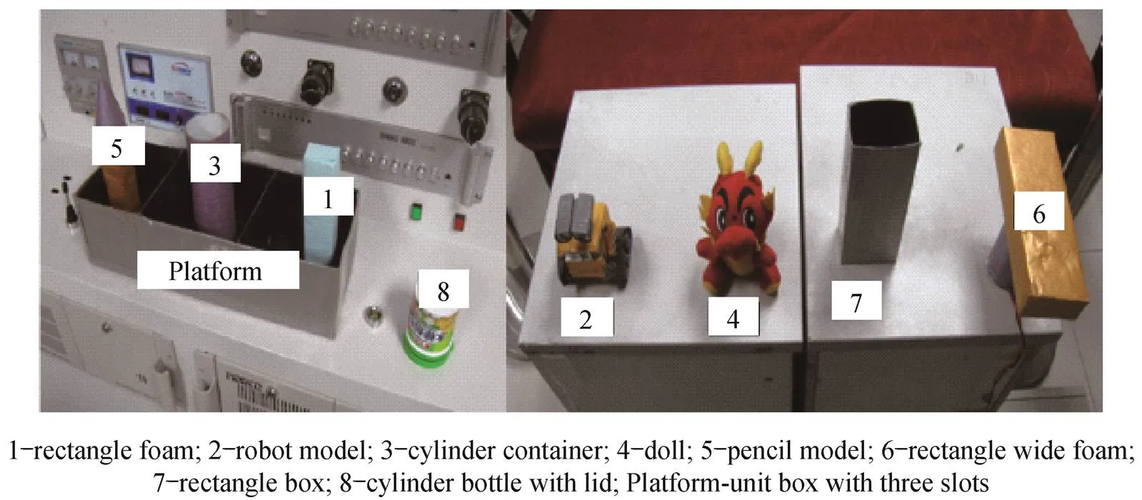
Fig. 10 Objects used in the experiment
3.1 Data glove experiment
To verify the performance of the proposed data glove, the operator needs to wear the data glove and executes different tasks. The estimated configuration of the hand is displayed. The experiment scenario of the data glove is shown in Fig. 11, and the hand configuration estimated by the data glove is shown in Fig. 12. It can be concluded that the data glove can capture the configuration of the hand well.
The data glove can communicate with the robotic hand through sockets. In the experiment, a three-finger Barrett hand is used, and the thumb, index finger, and middle finger of the data glove are mapped to the fingers of the robotic hand, respectively. The robotic hand can be controlled by the proposed data glove. As shown in Fig. 13, the robotic hand is half open in the left image and closed in the middle image, and a target object is grasped by the robotic hand with a precise grasp in the right image. Therefore, it can be concluded that the robotic hand is precisely controlled by using the proposed data glove.

Fig. 11 Hand placing flat on the table

Fig. 12 Hand screwing a cup lid by the handle

Fig. 13 Barrett hand controlled by the proposed data glove
3.2 Unit replacement experiment I and unit insertion/extraction experiment I
The unit replacement experiment I which is shown in Fig.14 is to take Unit 1 out of Platform and then replace it with Unit 2. The unit insertion/extraction experiment I is to insert Unit 1 extracted from Platform (unit box) into Unit 7. The operation steps are as follows.
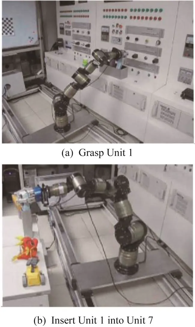
Fig. 14Schematic diagram of the unit replacement experiment I
Step 1 In the human-machine interaction interface module of the monitor system, click the “Platform” button on the manipulator control panel (see Fig. 9(c)), and then move the end-effectors to the place near Platform.
Step 2 In the gripper control panel (see Fig. 9(b)), check the three checking boxes denoted as “F1”,“F2”, and “F3”, and then drag the slider to the center-left position so that the robotic hand opens as a “C” shape.
Step 3 Adjust the configuration of the controller to control the movement of the end-effector. When the end-effector arrives to the position near Unit 1, click the “Send” button in the controller panel (see Fig. 9(a)) to make the end-effector move to the position.
Step 4 In the gripper control panel, check the three checking boxes after the “Close” button, and then click the “Close” button to grasp Unit 1 (see Fig. 14).
Step 5 Adjust the configuration of the controller to control the end-effector to move upward about 10 cm slowly, and extract Unit 1 from Platform.
Step 6 In the manipulator control panel, click the “Table” button to move the end-effector to Unit 7.
Step 7 Move the end-effector to the top of Unit 7, and then slowly move it down to insert the object into Unit 7 (see Fig. 15). Open the gripper, and put Unit 1 down. Then, the insertion/extraction experiment I is done.
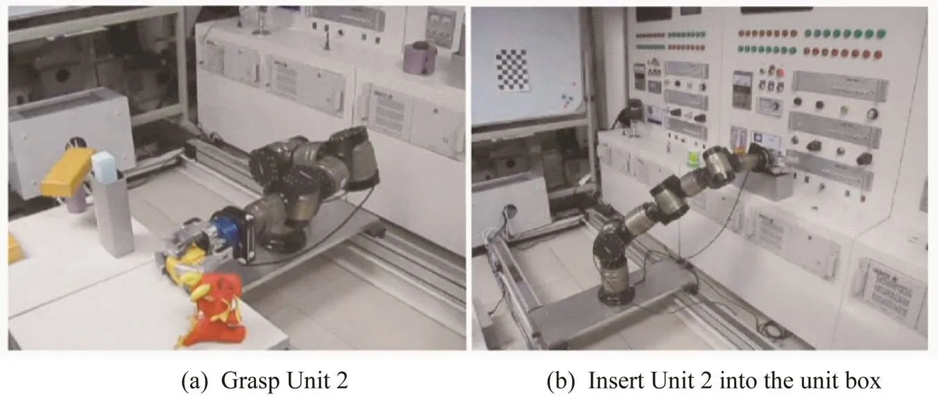
Fig. 15 Schematic diagram of the insertion/extraction experiment I
Step 8 Move the end-effector to Unit 2, close the gripper, and grasp Unit 2 (see Fig. 15).
Step 9 Click the “Platform” button so as to move the end-effector to the position near the “Platform”, and then stop above the empty slot of “Platform”.After that, open the gripper, and put Unit 2 into “Platform”(see Fig. 15). Then, the unit replacement experiment I is done.
3.3 Unit replacement experiment II
The unit replacement experiment II which is shown in Fig.15 is to take Unit 3 out of Platform (unit box) and replace it with Unit 4. The operation steps are as follows.
Step 1 Adjust the configuration of the controller, and move the end-effector to the front of Unit 3. Open the gripper. Then, move the gripper to the appropriate location slowly, and close it to grasp Unit 3. Adjust the controller to lift the end-effector slowly, and grasp Unit 3 from Platform (see Fig. 16).
Step 2 Click the “Table” button to move the end-effector to the vicinity of the table. Control the end-effector to move to Unit 2, and open the gripper to put Unit 3 down.
Step 3 Move the end-effector to the appropriate location, and close the gripper to grasp Unit 4 (see Fig. 16). Move the end-effector to the position above Platform, and insert Unit 4 into Platform (see Fig. 16). Then, the Unit replacement experiment II is completed.
3.4 Unit replacing experiment III, insertion/extraction experiment II, and object capture experiment
The unit replacing experiment III and the insertion/extraction experiment II are to replace Unit 5 with Unit 6 and insert Unit 5 into Unit 3. The object capture experiment is to grasp Unit 6 while it is slowly rotating. The operation steps are as follows.
Step 1 Move the end-effector to an appropriate position, and grasp Unit 5 from Platform (see Fig. 16). Take out Unit 5 and insert it into Unit 3 on the table (see Fig. 17).
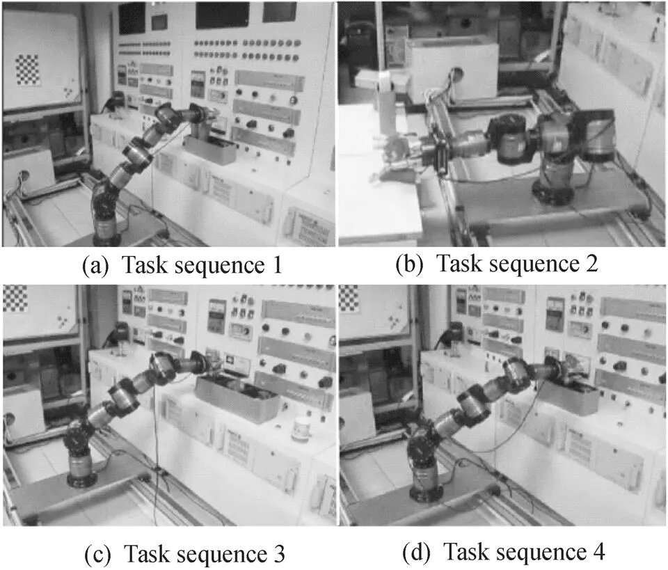
Fig. 16 Schematic diagram of the unit replacement experiment II
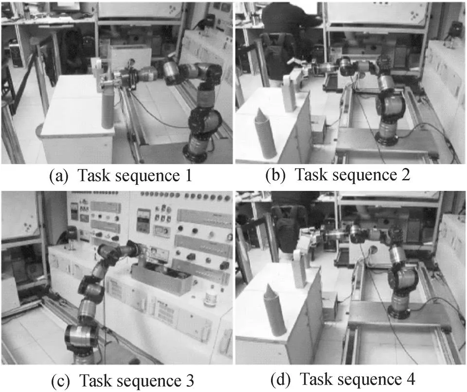
Fig. 17 Schematic diagram of the unit replacing experiment III, the insertion/extraction experiment II, and the object capture experiment
Step 2 Open the gripper to the shape of “C” as in the first experiment, and control the end-effector to slowly approach the moving object of Unit 6. In view of the delay of 10 s, move the end-effector to the moving path of Unit 6 (see Fig. 17). To prevent Unit 6 from moving, close the gripper, and grab Unit 6 (see Fig. 17). Move the end-effector so that Unit 6 can get rid of the rotation axis.
Step 3 Insert Unit 6 into Platform (see Fig. 17). Then, unit replacement experiment III is done.
3.5 Insertion/extraction experiment III
The insertion/extraction experiment III is to uncover the lid of Unit 8 and cover it. First, move the manipulator to the approximate location, and then grasp the lid part of Unit 8 (see Fig. 18(a)). Lift the end-effector about 6 cm to make the lid of Unit 8 away from the bottle (see Fig. 18(b). Then, lower the end-effector about 6 cm, and open the gripper. At last, put the lid on its original position. The insertion/extraction experiment III is done.
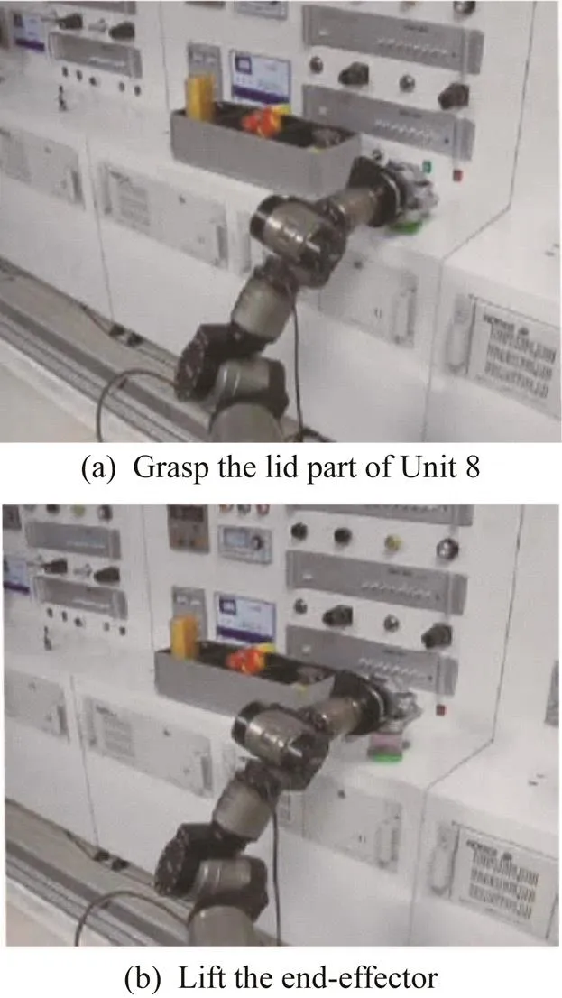
Fig. 18Schematic diagram of the insertion/extraction experiment III
4 Conclusions
Teleoperation is an important approach for robotic operation. In this paper, a robotic teleoperation system is proposed. It can simulate teleoperation tasks in the case of time-delay communication. A new visual object tracking method based on structured linear coding is used in its image acquisition system. A series of experiments are successfully conducted in the proposed system, and the results verify its effictivenss. In the future, the robotic teleoperation system can achieve more precise manipulation by adding multimodal sensing information. It is believed that some new intelligent designs are needed for the control of the unknown dynamics system[17-18].
[1] LEHNER H, SCHUSTER M J, BODENMULLER T, et al. Exploration of large outdoor environments using multi-criteria decision making[C]// 2021 IEEE International Conference on Robotics and Automation. Washington, D.C., USA: IEEE Press, 2021: 5163-5169.
[2] DU G, HAN R, YAO G, et al. A gesture-and speech-guided robot teleoperation method based on mobile interaction with unrestricted force feedback[J]. IEEE/ASME Transactions on Mechatronics, 2021, 27(1): 360-371.
[3] DIFTLER M A, CULBERT C J, AMBROSE R O, et al. Evolution of the NASA/DARPA robonaut control system[C]// 2003 IEEE International Conference on Robotics and Automation. Washington, D.C., USA: IEEE Press, 2003: 2543-2548.
[4] CUI J,TOSUNOGLU S, ROBERTS R, et al. A review of teleoperation system control[C]// Proceedings of the Florida Conference on Recent Advances in Robotics. Boca Raton, FL: Florida Atlantic University, 2003: 1-12.
[5] CHU M, CUI Z, ZHANG A, et al. Multisensory fusion, haptic and visual feedback teleoperation system under IoT framework[J]. IEEE Internet of Things Journal, 2022. DOI: 10.1109/JIOT.2022.3167920.
[6] FENG K, XU Q, TAM L M. Design and development of a teleoperated robotic microinjection system with haptic feedback[J]. IEEE Robotics and Automation Letters, 2021, 6(3): 6092-6099.
[7] TROY J J, ERIGNAC C A, MURRAY P. Haptics-enabled UAV teleoperation using motion capture systems[J]. Journal of Computing and Information Science in Engineering, 2009, 9(1):011003.
[8] TALASAZ A, PATEL R V, NAISH M D. Haptics-enabled teleoperation for robot-assisted tumor localization[C]// 2010 IEEE International Conference on Robotics and Automation. Washington, D.C., USA: IEEE Press,2010: 5340-5345.
[9] MARVASI-ZADEH S M, CHENG L, GHANEI-YAKHDAN H, et al. Deep learning for visual tracking: a comprehensive survey[J]. IEEE Transactions on Intelligent Transportation Systems, 2021, 23(5):3943-3968.
[10] LI P, WANG D, WANG L, et al. Deep visual tracking: review and experimental comparison[J]. Pattern Recognition, 2018, 76: 323-338.
[11] DANELLJAN M, GOOL L V, TIMOFTE R. Probabilistic regression for visual tracking[C]// Proceedings of the IEEE/CVF Conference on Computer Vision and Pattern Recognition. Washington, D.C., USA: IEEE Press, 2020: 7183-7192.
[12] SMINCHISESCU C, TRIGGS B. Estimating articulated human motion with covariance scaled sampling[J]. The International Journal of Robotics Research, 2003, 22(6): 371-391.
[13] LIU H, SUN F. Efficient visual tracking using particle filter with incremental likelihood calculation[J]. Information Sciences, 2012, 195: 141-153.
[14] MEI X, LING H. Robust visual tracking and vehicle classification via sparse representation[J]. IEEE Transactions on Pattern Analysis and Machine Intelligence, 2011, 33(11): 2259-2272.
[15] LIU H, YUAN M, SUN F, et al. Spatial neighborhood-constrained linear coding for visual object tracking[J]. IEEE Transactions on Industrial Informatics, 2013, 10(1): 469-480.
[16] WANG J, YANG J, YU K, et al. Locality-constrained linear coding for image classification[C]// 2010 IEEE Computer Society Conference on Computer Vision and Pattern Recognition. Washington, D.C., USA: IEEE Press, 2010: 3360-3367.
[17] XU B, YANH C, SHI Z. Reinforcement learning output feedback NN control using deterministic learning technique[J]. IEEE Transactions on Neural Networks and Learning Systems, 2013, 25(3): 635-641.
[18] XU B, SHI Z, YANG C. Composite fuzzy control of a class of uncertain nonlinear systems with disturbance observer[J]. Nonlinear Dynamics, 2015, 80(1): 341-351.
date:2022‑05‑23;
date:2022‑07‑10
Chinese Library Classification: TP 249
A
10.19328/j.cnki.2096⁃8655.2022.04.011
NSFC-Shenzhen Robotics Research Center Project (No. U2013207) and the Beijing Science and Technology Plan Project (No. Z191100008019008).
SUN Fuchun (1964—), male, full professor. His main research interests include cross‑modal learning, active perception, and precise operation and teleoperation.