应用于髋臼杯的TC4激光熔覆涂层工艺及性能
陈劲松,袁振东,沈理达,姜凌云,鲍恩泉,杨 昊,唐家铖
(1.江苏海洋大学 机械工程学院,江苏 连云港 222005;2.南京航空航天大学 机电学院,江苏 南京 222005)
1 Introduction
One of major concerned issues in hip replacement is how to reduce and avoid long-term loosening of the implanted prosthesis.At present,a widely used method is to coat the surface of the prosthesis using various technologies,such as plasma spraying[1-3],micro-bead or wire sintering[4],laser sintering[5]and direct energy deposition[6],so that the prosthesis will be relatively stably combined with bones.However,these methods are all limited by the low bonding strength between coatings and substrates,which hinders the bone to grow in.When the debris generated by the wear of the articular surface increases gradually,osteolysis will take place at the interface,thus leading to loosening and failure of the prosthesis.The surface of three-dimensional(3D)printed metal acetabular cups is easy for bone to grow into a trabecular structure[7-8].However,high price and long production time render it unsuitable for mass production and promotion.
Laser cladding,as a new generation of surface modification technology,has been widely used in many fields,such as aerospace,automobile manufacturing and energy engineering[9-11].Combined with a 3D control system,cladding layers can be stacked layer by layer with special structures on the surface of the substrate.They provide suitable media for nutrient transport as well as inward growth and osteocyte differentiation[12-14],and thus the surfaces of acetabular cups are well biocompatible.Moreover,with low costs and high cladding efficiency,the laser cladding has great application potentials[15].This research simulated laser cladding on TC4 applied on an acetabular cup and studied cladding process.
2 Experimental
2.1 Materials
Commercial Ti-6Al-4V extra-low interstitial(ELI)powder provided by EOS Gmb H was used for laser cladding,which was confirmed to ISO 5832-3 and ASTM F1472 standards.Ti-6Al-4V ELI titanium alloy,as a kind of damage-tolerant titanium alloy with a low interstitial element content (Table 1),had the characteristics of medium strength,high damage tolerance and long fatigue life.A typical SEM image of the powder under a Hitachi S-4800 scanning electron microscope(SEM)is shown in Fig.1.The major particles showed a high degree of sphericity with a few of small satellite particles,and the particle size ranged from 10 to 60μm.

Table 1 Chemical composition of Ti-6Al-4V ELI powder
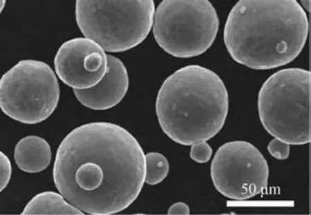
Fig.1 SEM image of TC4 powder particles
2.2 Laser cladded acetabular cups
The surface of an acetabular cup was cladded using MPC1800X cladding equipment produced by Insstek Company in South Korea.A YLR-300 fiber laser was used and coaxial powder feeding was adopted for powder feeding.Fig.2 shows a schematic diagram of the cladding process.In the equipment,a 3D control system was applied into the laser cladding system,to allow not only cladding on two-dimensional(2D)planes,but also on various complex curved surfaces.
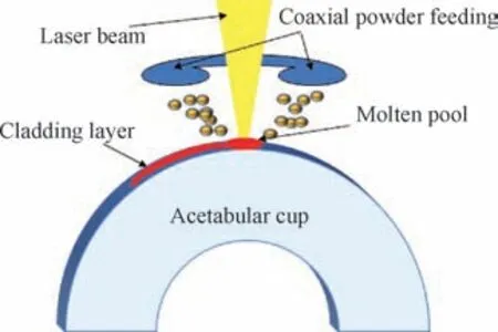
Fig.2 Schematic diagram of laser cladding acetabular cup
A cladding path was designed by UG modeling software installed with porous cam lug-in components.In order to make cladding layers on the surface of the acetabular cup more biocompatible,the designed special cladding path was used to process the surface.A square-wave path was utilized for cladding,as displayed in Fig.3.The square-wave path could allow a gap equal to the diameter of a molten pool between two adjacent cladding layers,and the length of each segment of the cladding path was not longer than twice the diameter of the molten pool.After cladding,a spatially regular porous biological structure was formed by cladding layers on the surface of acetabular cups,which made cladding layers had a suitable cladding density and biocompatibility.Under a certain laser power and powder feed rate,cladding density of the cladding layers was mainly determined by the length of each segment of the cladding path.
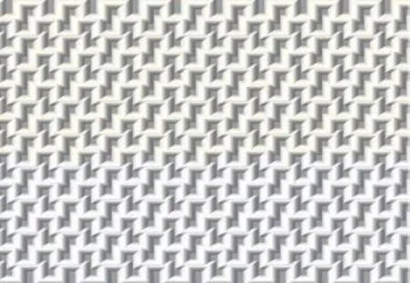
Fig.3 Laser square wavy path diagram
2.3 Finite element simulation of laser cladding
ANSYS Parameter Design Language was used to simulate single-pass laser cladding process,so as to explore the temperature fields of the high-precision laser cladding under certain parameters.SOLID70 3D 8-node thermal analysis elements were used for mapped mesh generation,and each node had degrees of freedom of temperature and displacement.The element birth and death technique was employed to simulate moving process of the molten pool,and the elements that have been deactivated were activated with the movement of the molten pool and then simulated and calculated.By simulating single-pass laser cladding with the software,the distribution results of temperature fields in the molten pool at different moments and temperature gradients in different directions were obtained.The standard parameters were used for simulation.Parameters about the laser and powder feed are listed in Table 2.

Table 2 High precision laser cladding parameters
2.4 Optimization of high-precision laser cladding process
An orthogonal test table with four factors and three levels was designed for the test.Four test factors,namely bead spacing(A),row spacing of beads(B),laser beam offset(C)and powder feed rate(D)for the laser cladding were selected.During the test,on the premise of laser power of 70 W,cladding rate of 1.5 m/s and spot diameter of 0.4 mm,three levels of 0.8,0.9 and 1.0 mm were selected for the bead spacing(A),and three levels of 0.2,0.3 and 0.4 mm were selected for the row spacing of beads(B).Moreover,three levels of the laser beam offset(C)were set as 0.6,0.8 and 1.0 mm and three levels,1.5,2 and 2.5 g/s,were set for the powder feed rate(D).According to the selection rules of different factors and levels in the standard orthogonal table,nine groups of tests with different combinations of process parameters were obtained,specifically demonstrated in Table 3.
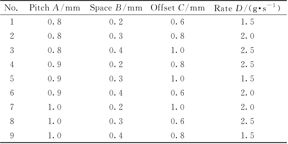
Table 3 Orthogonal experimental table
The quality of cladding layers was comprehensively evaluated in accordance with density,thickness and cladding defects.The cladding layer with the lowest density among all cladding samples was selected,and the density index(DI)of the sample was defined as 1.The ratio of the density of the sample to that of a sample wasDIof the latter.The thickness of cladding layers in the range of 0.7 to 1.0 mm was directly taken as the thickness index(TI)of the samples.For the cladding layers printed in ideal state,the cladding defect index(CDI)was defined as 1.However,in general,CDIis smaller than 1,because it is difficult to avoid various defects on the cladding surface.CDIof each cladding sample was valued in the range of 0-1 according to degree of cladding defects.The quality of cladding layers was evaluated by comprehensive performance index(CPI)and it was speculated thatDI,TI andCDIseparately accounted for 45%,35%and 20%of the CPI.The CPI is calculated through the following formula(1).

2.5 Test of mechanical performances
A CMT510 microcomputer controlled electronic universal testing machine was used in a quasi-static compression test.A columnar substrate was selected as the sample,on the top of which cladding was performed.The sample with an upper diameter of 30 mm and a lower diameter of 38 mm showed a height of 80 mm and a cladding area of 706.86 mm2.The quasi-static compression was conducted on the sample at a constant compression rate of 0.1 mm/min for 3 min.
A spalling test is to test the quality of metallurgical bonding between cladding layers on the surface of the acetabular cup and the substrate.Standard sheet test samples were selected,and the process parameters were the same as those used in the compression test.A high-pressure air blower was firstly used to blow debris on the surfaces of three samples from different directions and a BSA124S electronic balance with a precision of 0.1 mg was utilized for weighing and measurement.The samples were placed in an ultrasonic cleaning machine for ultrasonic cleaning with purified water.After being cleaned for 20 min,they were put into an electric blast drying oven for drying and weighing.After performing the bending test for 3 min on the samples placed on a three-point bending fixture,the test was repeated for several times until the mass of the samples did not change.The mass of the samples obtained from the last drying was taken as the mass of the samples after the spalling test,and the three samples were subjected to the three-point bending test in turn.
3 Results and discussion
3.1 Finite element simulation of laser cladding
Table 4 shows temperature in the center of the spot and the diameter of the circular area where the temperature reaches the melting point at different time when the laser beam moves.It can be seen from the table that the temperature in the center of spot reaches 1 830℃after laser irradiation for 0.03 s,which is higher than 1 668℃,the melting point of TC4 cladding materials.As time goes on,the temperature in the center of spot rises steadily,and the shape of the molten pool reaches a quasi-steady state.

Table 4 Temperature and diameter of the spot center at different time
3.2 Process optimization
As shown in Table 5,CPIof the ninth sample is the highest among them,whose process parameters are bead spacing of 1 mm,row spacing of beads of 0.4 mm,laser beam offset of 0.8 mm and powder feed rate of 1.5 g/s for the laser cladding.
The results of extreme value analysis were utilized to determine the influencing degree of different process parameters on the coating quality.The extreme value analysis was carried out by comparing the results of orthogonal test shown in the table,where the sum value of each of parameters in each of horizontal row in table is represented by Ki,in whichi=1,2,3.As displayed in Table 6,the bead spacing during the laser cladding has the largest influence on density,followed by the powder feed rate,while the laser beam offset during laser cladding exerts the smallest effects on density.For the thickness of cladding layers,the powder feed rate has the largest influences,followed by the bead spacing,while row spacing of beads shows the smallest impacts onTIof cladding layers.In terms of cladding defects,they are significantly affected by the powder feed rate,while the other three parameters differ slightly in their influences on cladding defects.To sum up,the bead spacing during laser cladding significantly influences comprehensive performances,followed by the row spacing of beads during laser cladding,while the effect of the powder feed rate on comprehensive performances is the smallest among all parameters.In accordance withkvalues,the optimal parameter combinations of different indexes are shown as follows:the optimal combinations of process parameters for density,thickness of cladding l ayers,cladding defects and comprehensive performance areA3B3C3D1,A1B2C3D3,A1B2C1D1andA3B3C3D1.In other words,to obtain the highest comprehensive perfor-mance,the bead spacing,row spacing of beads,laser beam offset and powder feed rate during laser cladding should be 1 mm,0.4 mm,1 mm and 1.5 g/s,respectively.

Table 5 Orthogonal experiment table
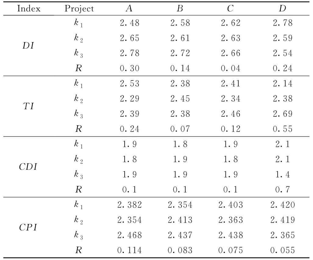
Table 6 Analysis of Laser cladding coating
3.3 Mechanical performance
Under normal conditions,the stress-strain curve of a porous structure under compression is divided into three parts,corresponding to an elastic stage,a plateau stage and a densification stage.The section in the elastic stage shows a sharp increase trend in a short strain range,while that in the plateau stage presents an undulating broken line.Moreover,the part in the densification stage demonstrates a rising and slightly fluctuating zigzag line.
It can be observed from Fig.4 that stress-strain curves of the three samples are more consistent with the characteristics in the densification stage,and are quite different from stress-strain curves of the standard porous structure under compression.
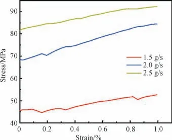
Fig.4 Compressive stress-strain curves of samples with different powder feeding rates
Firstly,the porosity of a standard porous structure is uniform,while high-precision laser cladding layers are not uniform in its porosity in space,and the closer the layer to the substrate is,the higher the density of the cladding layer will be.Secondly,to ensure test accuracy and results reliable,the total displacement under compression is only 0.3 mm in the test,and only 30 groups of test data are obtained from each compression.Due to the compression in only partial thickness of the whole cladding layer,the stress-strain curve cannot show the mechanical performances of the whole cladding layer.
The spatial structure of the cladding layers shows that the closer the cladding layer to the substrate is,the denser it will be,which corresponds to the broken line trend on the stress-strain curve under compression.During this process,yield and failure appear in the cladding path and failure firstly occurs in the position with weak strength and stress concentration.As demonstrated in Fig.4,when the powder feed rate is 1.5 g/s,the stress at the lowest point in the image is 44.658 MPa,while that at the highest point is 52.720 MPa.Before strain is reaches 30%,the image shows a fluctuating trend and then a constant increase trend,and fluctuation appears again till the strain reaches 85%.As the powder feed rate is 2.0 g/s,the broken line fluctuates slightly and the stresses at the lowest and highest points in the curve are 68.179 MPa and 84.448 MPa,respectively.The curve is growing in the figure and only fluctuates slightly in the early stage.When the powder feed rate is 2.5 g/s,the stresses at the lowest and highest points in the figure are 81.610 MPa and 92.338 MPa,respectively.The broken line shows a steady upward trend generally,and slightly fluctuation is found when the strain is about 85%.At a small powder feed rate,there are fewer cladding particles and agglomeration in cladding layers,fluctuation similar to that on the stress-strain curve of the porous structure under compression is shown in the figure.As the powder feed rate increases,due to influences of cladding particles and agglomeration,the broken line fluctuates not so obviously and the stress at the highest point is 92.338 MPa.
According to the spalling test results in Table 7,spalling degree is related to cladding particles and agglomeration on cladding layers of the samples.When the powder feed rate is low,a few particles are attached on the cladding layers,and cladding layers thus have a good metallurgical bonding with the substrate and are not easy to peel off.However,some cladding particles cohere unsteadily to cladding layers and peeled off from cladding layers after the bending test.With increasing powder feed rate,a lot of cladding particles are attached on cladding layers.Many particles unsteadily adhere to cladding layers are peeled off after the bending test and the samples produce lots of debris after the test.Through analysis,when the powder feed rate is smaller than 2 g/s,it greatly affects spalling amount of cladding layers.As the powder feed rate is larger than 2 g/s,spalling amount of cladding layers is slightly influenced by powder feed rate.Therefore,the powder feed rate can be selected as about 1.5 g/s,which can largely reduce debris spalling from cladding layers.If the acetabular cup implanted in human body has more debris peeled out,it is easy to cause inflammation and other symptoms.Therefore,when cladding the surface of the acetabular cup at a high precision,it is necessary to set a proper powder feed rate to reduce cladding defects,such as cladding particles and agglomeration.

Table 7 Mass reduction of sample after test
4 Conclusion
This research designed an orthogonal test to test the influences of bead spacing,row spacing of beads,laser beam offset and powder feed rate on coating quality.The main results include the following factors.
1.With increasing of powder feeding rate,the number of unstable connections between cladding particles and cladding layer increased while the amount of peeling increased.The suitable powder feeding rate is about 1.5 g/s.
2.Based on the evaluation of the surface quality and spalling amounts of cladding layers,the best comprehensive performance is obtained when the bead spacing,row spacing of beads,laser beam offset and powder feed rate during laser cladding are 1 mm,0.4 mm,1 mm and 1.5 g/s.
3.High-precision laser cladding of the acetabular cup was carried out by designing the square-wave cladding path.The porous structure ensures biomechanical performance,proving that it is feasible to apply high-precision cladding layers on the acetabular cup in orthopedics.

