Strain-mediated magnetoelectric control of tunneling magnetoresistance in magnetic tunneling junction/ferroelectric hybrid structures
Wenyu Huang(黄文宇) Cangmin Wang(王藏敏) Yichao Liu(刘艺超) Shaoting Wang(王绍庭) Weifeng Ge(葛威锋)Huaili Qiu(仇怀利) Yuanjun Yang(杨远俊) Ting Zhang(张霆) Hui Zhang(张汇) and Chen Gao(高琛)
1School of Physics,Hefei University of Technology,Hefei 230009,China
2School of Microelectronics,Hefei University of Technology,Hefei 230009,China
3Hefei National Laboratory for Physical Sciences at Microscale(HFNL),University of Science and Technology of China,Hefei 230026,China
4School of Physical Sciences,University of Chinese Academy of Sciences,Beijing 100049,China
Keywords: tunneling magnetoresistance,magnetic tunnel junction(MTJ),multiferroic heterostructure,magnetoelectric coupling
1. Introduction
In the rapid development of information storage technology, research on random-access memory with high density, high speed, non-volatility, and low-energy consumption is challenging.[1-4]The ferroelectric (FE) and magnetic constituents in composite multiferroic materials can interact directly or indirectly through magnetoelectric effects,which potentially enables electric-field (E-field) control of magnetization switching to solve this challenge. There have been extensive investigations on growing ferromagnetic thin films, multilayers, and magnetic device prototypes on FE substrates to study E-field control of magnetism. The central goal is to find an energy-efficient way of using voltage across the FE layer for reversible and nonvolatile manipulation of magnetic and resistance states. As one of the most fascinating spintronic devices,magnetic tunnel junctions(MTJs),with excellent tunneling magnetoresistance (TMR) effects, are attracting great interest in the fundamental sciences and in practical applications.[5,6]Many studies used high-density currents to manipulate MTJs via spin-transfer torque effects or external magnetic fields.[1,2]However,this is an energy-consuming method.
By taking advantage of magnetoelectric effects in composite multiferroic heterostructures,[3,4]we can use E-fields to control magnetic anisotropy, TMR, and magnetic interactions in the ferromagnetic layers of the MTJ.[7-9]Integration of MTJs into FE constituents enables novel multiferroic magnetoelectric devices,[10]such as magnetoelectric magnetic random-access memory,[11]magnetic sensors, and tunable inductors.[12,13]Roschewskyet al.observed that the coercive field and the switching current decrease by approximately 2% under mechanical strain in the perpendicular MTJ.[14]These results are attributed to magneto-elastic coupling and have also been applied in the design of MTJ-based pressure sensors.[15,16]Moreover,MTJ/FE hybrid multiferroic heterostructures were theoretically proposed for new-generation non-volatile magnetoelectric random-access memory,[11,17]and were soon verified experimentally.[18-22]Pertsevet al.[17]and Nanet al.[11]theoretically proposed a spin valve or an MTJ fabricated on an FE substrate,and used phase-field simulations to demonstrate a simple and new pathway for highperformance magnetic random-access memories.[11]Then,Liet al.successfully demonstrated reversible continuous magnetization rotation and manipulation of the TMR at room temperature in an AlOx-based MTJ/(001)-PMN-0.3PT hybrid heterostructure by E-fields.[18]Zhaoet al.demonstrated significant voltage manipulation of the TMR in an MgO-based MTJ grown on a (001)-PMN-0.3PT FE substrate with an inplane E-field configuration.[19]Chenet al.further optimized the architecture of the MgO-based MTJ/PMN-xPT multiferroic heterostructure and achieved giant reversible and nonvolatile E-field manipulation of magnetoresistance to about 55%at room temperature without the assistance of a magnetic field.[23]Yanget al.fabricated an MgO-based MTJ/(011)-PMN-0.3PT magnetoelectric hybrid structure and observed angle-dependent magnetic switching behavior under the application of E-fields.[24]So far,most research on MTJ/FE hybrid multiferroic heterostructures is generally focused on the MTJ with a memory configuration. However,tunneling magnetoresistance and magnetization switching of the MTJ in a sensory configuration is still lacking in these types of hybrid multiferroic heterostructures. Moreover, E-field-induced anisotropic strain control of magnetization switching in MTJ/FE hybrid structures has been extensively studied, as mentioned above.[21,25,26]But E-field-induced isotropic strain on magnetic states and TMR in such an MTJ-based multiferroic heterostructure is not well understood. In particular,the isotropic strain induced by E-fields in the(001)-oriented FE layer may be more efficient than the anisotropic strain(most commonly used (011)-cut FE) to achieve 180°magnetization switching in the perpendicular magnetic tunnel junction, which has received extensive attention due to high thermal stability at a reduced dimension, low-current-induced magnetization switching and a high TMR ratio all at the same time.[27-30]Additionally, the exploration of different architectures of in-plane or perpendicular MTJ/FE multiferroic heterostructures offers new possibilities for high-performance memory and logic devices. Therefore, further optimization of hybrid MTJ/PMNxPT multiferroic heterostructures is meaningful for potential spintronic and electronic applications,even without the assistance of external magnetic fields.[31,32]
Motivated by the aforementioned achievements in inplane MTJ-based multiferroic heterostructures, herein, we demonstrate E-field control of magnetization rotation in a sensory MTJ/FE (001)-PMN-0.3PT hybrid multiferroic heterostructure at room temperature. Without a magnetic-field bias,the TMR ratio controlled by E-fields was obvious. Moreover, when a magnetic field was applied along the minor axis of the MTJ,the butterfly loop also changed significantly.Based on this multiferroic heterostructure, we also demonstrated that the MTJ can be used as a strain-sensitive sensor with a considerable gauge factor (GF). The hybrid structure exhibits low power consumption and measurable micro-strain,which enables an in-depth understanding of E-field-controlled magnetization in MTJ/PMN-xPT multiferroic heterostructures and potential strain-sensing applications.
2. Experimental methods
Fabrication of MTJs on pre-oxide (001)-Si wafers was previously reported in detail.[33]MTJ dies were cut from a Si wafer into 3-mm widths and lengths. The Si substrate was approximately 280-µm thick. The top and back electrodes used for the applied E-fields across the thickness direction of the PMN-0.3PT substrates were made via electron-beam evaporation. The thickness was approximately 700 µm to prevent cracking of the PMN-0.3PT FE substrate under E-field cycling. A 100-nm Au film was deposited on a 10-nm Ti adhesive layer at room temperature. The Ti thin film enhanced adhesion between the Au and the PMN-0.3PT substrates. Then,the Au/Ti/PMN-0.3PT/Ti/Au samples were annealed in air for one hour at 200°C and naturally cooled to room temperature for better piezo-strain transfer. The MTJ dies were glued on one side of the Au/Ti/PMN-0.3PT/Ti/Au with epoxy resin(M-Bond 610, Vishay Precision Group, Inc. USA).[34]The MTJ/Au/Ti/PMN-0.3PT/Ti/Au hybrid structures were cured for 24 hours at room temperature to dry the glue. The TMR was measured within situmagnetic fields using a source meter(Keithley 2400, USA)in four-probe mode. Thein-situEfield was applied via a high-voltage source (Keithley 2410,USA). The in-plane strain was measured by gluing strain gauges (L2A-06-06LT-350, Micro-Measurements, USA) on the PMN-0.3PT single crystals.
3. Results and discussion
3.1. Architecture of hybrid multiferroic heterostructure
Figure 1(a) is a schematic of an MTJ/PMN-0.3PT hybrid multiferroic heterostructure. The Si substrate with the MTJ array is glued on the FE PMN-0.3PT single crystal with epoxy resin. We etched the MTJs into 6 µm×18 µm ellipses. The long axis of the ellipse is along the [100] direction, and the short axis is along the [010] direction of the PMN-0.3PT substrate, as shown in Fig. 1(a). The illustration on the left side of Fig. 1(a) shows an enlarged view of the MTJ layer structure: Au/Ru/Ta/CoFeB (free layer, FL)/MgO (tunneling layer)/CoFeB (reference layer,RL)/Ru/CoFe/IrMn/CoFe/Ta/SiO2/Si. The E-fields are applied along the PMN-0.3PT thickness direction through the top and bottom electrodes. Figure 1(b) shows the major and minor loops of an MTJ array with the applied magnetic fields along the long and short axis of the MTJs, respectively. The TMR ratio is defined as [R(H)-R0]/R0×100%. It is approximately 35%along the minor direction. According to the linear fitting results of the minor curve as the magnetic field scans back and forth within±20 Oe (see Fig. S1 in the supplementary material),a small difference in the fitting slope indicates a good linear region,as shaded in Fig.1(b). Additionally, a small hysteresis exists in the minor loop, which could be attributed to the magnetic hysteresis of CoFeB FL and N´eel“orange-peel” coupling due to the roughness of the interface between the MgO barrier and CoFeB layer.[35,36]In contrast,the TMR ratio is very small along the major direction,which is consistent with the previous report.[37]These results strongly indicate that the MTJ array is in a sensory configuration.[20,38]
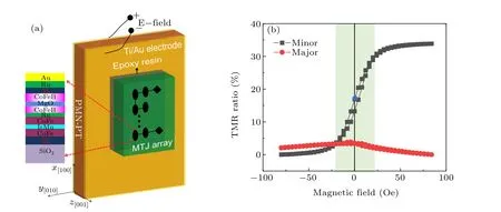
Fig.1. (a)A schematic of magnetic tunneling junction/ferroelectric(001)-oriented PMN-0.3PT(MTJ/PMN-0.3PT)hybrid multiferroic heterostructures. The inset is a cross-section of one MTJ layer architecture. The thicknesses of the multilayers in the heterostructure are not drawn to scale. (b) The tunneling magnetoresistance ratio(TMR)measured along the major(solid circles)and minor(solid squares)axes of the MTJs.
3.2. Magnetization configuration
Figure 2(a)shows the magnetization configuration in the MTJ. The blue arrow indicates the magnetization direction of the CoFeB FL, and the red arrows show the magnetization direction in the SAF layer. The antiferromagnetic layer is drawn with a double arrow. The angle between the applied magnetic field and thex-axis is given byα. The reference and pinned layers are pinned along the-y-axis through Ruderman-Kittel-Kasuya-Yosida(RKKY)interactions.[33,37]
To study the magnetization switching behavior, circle transfer curve (CTC) measurements were performed by sweeping the magnetic field over 360°with a constant magnitude to analyze the TMR angular dependence of the MTJ.[22]Figure 2(b) shows the TMR ratios under 5-Oe, 20-Oe, 50-Oe, and 60-Oe magnetic fields. In the CTCs, the maximal and minimal TMR ratios under all magnetic fields can be obtained when the fields were at 90°and 270°, respectively.This indicates that the magnetization coherently rotates with the changing direction of the magnetic field,regardless of the field strength. Consequently, we could determine the highresistance state with an antiparallel magnetization configuration(labeled as“2”),and the low-resistance state with a parallel configuration (labeled as “4”), as shown in Figs. 2(d) and 2(f), respectively. In addition, the TMR ratios at the 0°and 180°angles are roughly equal and half the maximal value.This implies that the FL magnetization is perpendicular to that in the RL,as shown in Figs.2(c)and 2(e).The direction of RL magnetization is assumed to be locked by the antiferromagnetic coupling according to our previous reports.[24,39]Thus,the magnetic states of the MTJ/PMN-0.3PT multiferroic heterostructure are revealed, which helps us to understand magnetization switching under applied E-fields.
3.3. E-field-control of TMR without magnetic-field bias
To study E-field effects on the MTJ/(001)-PMN-0.3PT multiferroic heterostructure, we examine the relationship between the TMR and the applied E-field without a magneticfield bias, as shown in Fig. 3(a). Herein, the magnetic state is initialized by applying a saturated magnetic field of about +80 Oe along theyaxis and reducing it to zero, as marked by the blue solid circle in Fig. 1(b). The corresponding TMR ratio is also shown,which exhibited butterflylike behavior under the bipolar E-field cycling. The Efield-controlled junction-resistance change ratio without a magnetic-field bias is approximately +0.18% at +3 kV/cm,and is-0.27%at-1.4 kV/cm. This E-field-modulated TMR change ratio is comparable to the GMR(~0.1%-1%)at room temperature.[40,41]Figure 3(b)shows the loop of the in-plane strain along the isotropic direction [001] of the PMN-0.3PT under a scanned bipolar E-field. Comparing Figs. 3(a) and 3(b), the shape of the resistance versus electric field loop is similar to that of the strain versus E-field curve. Therefore,the in-plane strain induced by the E-field could play a role in the TMR modulation. Additionally, the butterfly-like curves in Figs. 3(a) and 3(b) are nearly opposite each other, which strongly indicates strain-mediated magnetoelectric coupling in the MTJ/PMN-0.3PT multiferroic heterostructures. The piezo-strain generated by the PMN-0.3PT layer is transferred to the FL.Thus,the magnetization rotation of the FL with respect to the RL(or PL)is modulated by the in-plane strain induced by the applied E-field via the inverse magnetostriction effect. This leads to TMR modulation by E-fields. It is worth mentioning that the piezo-strain for the PMN-0.3PT FE layer is indeed transferred to the silicon substrate surface by checking the Si(400)reflection shift through x-ray diffraction within situE-fields(not shown here).Accordingly,the free layer of the MTJ must feel the strain upon application of E-fields.[42]Furthermore, we propose three strategies to further enhance the tunability of the TMR ratio by E-fields as follows. (i)Direct growth of TMR multilayers on the PMN-0.3PT substrates rather than glued layers could ensure a high strain-transfer efficiency, certainly resulting in a high TMR ratio modulation by E-fields.[24](ii) Choosing a (011)-oriented ferroelectric layer probably increases the tunability of the TMR ratio due to the in-plane anisotropic piezo-strain.[24](iii) Selecting highly piezoelectric active materials, for example, a lead zinc niobate-lead titanate (PZN-PT) ferroelectric layer, can promise a large E-field-induced piezo-strain, and thus large TMR ratio modulation can be expected.[43]
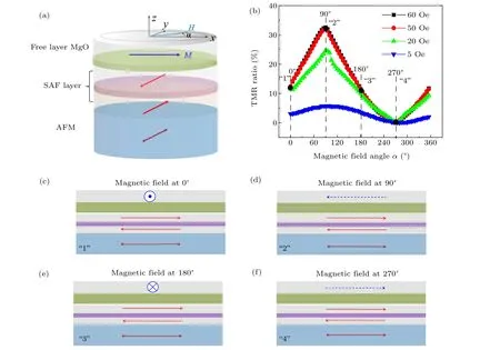
Fig.2. (a)A schematic of the magnetization configuration in the magnetic tunneling junctions. (b)The tunneling magnetoresistance ratio as a function of the magnetic fields and their azimuthal angles. (c)-(f)Configurations of the magnetization in the free and reference CoFeB layers under different directional external magnetic fields. The magnetization of the free layer was nearly coherently rotated by larger magnetic fields.

Fig.3. (a)Tunneling magnetoresistance as a function of the applied fields without a magnetic-field bias. (b)The strain vs. E-field loop of the(001)-PMN-0.3PT ferroelectric substrate. The arrow indicates the E-field scan direction. The solid circle represents the starting point of the E-field scan.
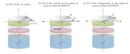
Fig.4. (a)The initial magnetization configuration of the magnetic tunneling junctions without magnetic field bias. (b)and(c)Schematics of the free layer rotated under E-field-induced tensile and compressive strains,without a magnetic-field bias,respectively.
To explain the magnetization reversal under the E-fields,we drew magnetization configurations in Fig. 4, which was an intuitive diagram to help readers create a concise and clear physical image. Figure 4(a) is the magnetization configuration under no magnetic or E-fields. Because of the small hysteresis[see Fig.1(b)],the FL magnetization is not completely aligned along the major axis of the MTJ (easy axis, e.a.) labeled byφ, which is the angle between the magnetizationMand thexaxis (or e.a.) of the MTJ. Herein,βis the angle of the magnetization direction of the FL and RL. Upon cycling the E-fields near the coercive field (~1.4 kV/cm), the tensile strain dominates over the compressive strain, as marked by the blue arrows in Fig. 2(b). The lowest free-energy is found when the magnetization is rotated to thex-axis direction due to a positive magnetostriction of the FL.This reduces the angleφ. Therefore,βdecreases, as shown in Fig. 4(b),and the junction resistance decreases according to Julliere’s model.[44,45]With further increases in the E-fields over the coercive field,compressive strain is dominant,as labeled by the orange arrows in Fig. 4(c). The FL magnetization is thus rotated out-of-plane to save the free energy.[19,46]Therefore,the magnetization,which was originally in-plane,is now upturned in Fig.4(c).Consequently,βincreases,and hence the junction resistance increases, as shown in Fig. 3(a). It is reasonably assumed that the direction of the RL magnetization is locked and not rotated because of the strong exchange bias field in the SAF layer,which has been confirmed in MTJ/(011)-PMN-xPT hybrid multiferroic structures.[24,39]
3.4. E-field-control of TMR with the assistance of magnetic fields
To confirm the strain-mediated magnetoelectric control of TMR,we applied a series of biased magnetic fields to perform the TMR measurements within situE-fields. This is because the TMR is actually spin-dependent.[47]Then, we could determine whether the FL magnetization rotates under E-fields.Herein,a typical case of±10 Oe is discussed in detail below and other similar cases of±5 Oe,±20 Oe along theyaxis are shown in Fig.S2(see the supplementary material). The+10-Oe magnetic field is applied along the minor axis(+y)and the-10-Oe field is along the-yaxis,as shown in Figs.5(a)and 5(b),respectively. The FL magnetization direction rotates towards the applied magnetic fields to lower the FL free energy because of the additional Zeeman energy. Therefore,βbecomes larger and smaller in the+10-Oe and-10-Oe magnetic fields, respectively, resulting in an increase and a decrease of the TMR,as shown in the left axis of Figs.5(c)and 5(d), respectively. The corresponding tunneling resistance change ratio is also respectively shown in the right axis of Figs. 5(c)and 5(d). Overall,comparing Figs.5(c)and 5(d),the shape of the tunneling resistance versus E-field curve is roughly opposite under the+10-Oe and-10-Oe magnetic fields. In detail,compared with Fig.3(a),the shape of the tunneling resistance versus E-field curves under magnetic fields is significantly different from that without a magnetic-field bias, strongly indicating the existence of strain-mediated magnetoelectric coupling between the FL of the MTJ and PMN-0.3PT FE layer.In addition, we have performed a repeated test, as shown in Fig.5(c),to ensure reproducible control of the tunneling resistance under the co-actions of E-fields and magnetic fields.The results of the two measurements are totally consistent,verifying that spin-dependent TMR is modulated by E-field-induced magnetization rotation of the FL via strain-mediated magnetoelectric coupling. As a confirmatory experiment,we further verified the dependence of tunneling resistance on the E-fields with magnetic fields along the±x-axis direction (see the details in Fig.S2 in the supplementary material),which is completely consistent with the case in Figs.5(c)and 5(d).

Fig.6. (a)and(b)Schematics of the FL magnetization rotated by electric-field-induced tensile strain in the vicinity of the coercive field, and compressive strain under the larger E-field with the +10-Oe magnetic field along the y axis, respectively. (c) and (d) Schematics of the magnetization of the free layer rotated by the E-field-induced tensile and compressive strains with the-10-Oe magnetic field along the y axis,respectively.
To understand E-field control of the tunneling resistance with the assistance of magnetic fields, we conduct a detailed analysis of magnetization rotation, as shown in Fig.6. In the vicinity of the coercive field,the in-plane tensile strain pushes the magnetization rotation towards the e.a., which decreases the angleφ,as shown in Fig.6(a). With the decrease ofφ,βdecreases,and the tunneling resistance near the coercive field thus decreases. This explains the reduction of the junction resistance in Fig. 5(c). In contrast, when the E-fields increase,the induced compressive strain causes the magnetization to rotate out-of-plane,leading to increasedβ,as shown in Fig.6(b).Hence,the TMR increases when the multiferroic heterostructure experiences a larger E-field and a+10-Oe magnetic-field bias. When a-10-Oe magnetic field is applied, the magnetization also rotates to the e.a. in the vicinity of the coercive field to save FL free energy, which reducesφ, as shown in Fig.6(c). Correspondingly,βincreases,leading to an increase in the TMR[Fig.5(d)]. When the E-fields increase further to saturation, the compressive strain induces the magnetization to rotate out-of-plane,andβincreases,as shown in Fig.6(d).Accordingly, the TMR increases under a high E-field and a-10-Oe magnetic field, which is also consistent with the observation in Fig. 5(d). Therefore, strain-mediated magnetoelectric control of the TMR is demonstrated,and the observed results could be understood from the magnetoelectric coupling between the FL and PMN-0.3PT FE layers. It is worth mentioning that both Figs. 4 and 6 are just intuitive diagrams to construct an intuitive physical picture for the E-field-induced change in the TMR ratio,presenting a qualitative understanding of magnetization switching rather than a quantitative result. We will obtain a quantitative angle rotation using micromagnetic simulations in the future.
3.5. Potential application of the hybrid multiferroic heterostructure
Earlier research on the applications of MTJs mainly focused on solid-state magnetic storage elements,[48]magnetic logic devices,[1]and magnetic field sensors.[10]According to the above studies, the MTJs may also have promising applications in strain sensors. In Fig. 7(a), the change ratio of the TMR is plotted as a function of the strain induced by unipolar E-fields under different magnetic-field bias. Overall, the change ratio increases with increasing unipolar compressive strain under relatively small-bias magnetic fields(0 Oe,5 Oe,and 10 Oe). However, increasing the magnetic-field bias decreases the change ratio,which may be attributed to increasing Zeeman energy under larger magnetic fields. In addition, the RL may have also been rotated under the larger magnetic field,resulting in a reduction of the TMR ratio change,[18]which will be further investigated in the future.
Then,we can calculate the GF of the MTJs in a multiferroic heterostructure according to[16]

whereεis strain, and ΔR=R-R0is the difference between the tunneling resistance and the initial resistance at an E-field of 0 kV/cm. The GF versus magnetic-field bias is shown in Fig.7(b).At 0 Oe,the GF is approximately 40,which is an average value compared with commercial metallic GF=2-5,[49]or silicon-based piezo-resistive GF = 40-180.[50]At 5 Oe and 10 Oe, the GF is reduced, because the external magnetic fields try to align the magnetization along their own directions.Moreover,the GF changed sign(-9.5)with further increases in the magnetic field up to 20 Oe, as shown in Fig. 7(b).It is expected that the GF should increase until the external magnetic field reaches the saturated magnetic field of the MTJs. Therefore,the GF in the MTJs is tunable with external magnetic fields, enabling applications as strain sensors with adjustable ranges. However, conventional fabricated strain sensors are fixed and cannot be adjusted.[49,50]According to these results, the MTJ/PMN-0.3PT multiferroic heterostructure could be used as standard equipment for strain calibration(including metallic, semiconductor, and MTJ-based sensors),with the advantages of compact architectures,small sizes,light weights, and high strain measurement accuracies via E-field control. In contrast, the conventional bending apparatus for strain calibration is bulky,large,and heavy,and has difficulty in strain control.[50]
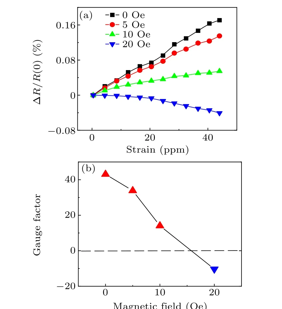
Fig.7. (a)The relationship between the tunneling magnetoresistance change ratio and strain induced by E-fields in the MTJ/PMN-0.3PT multiferroic heterostructure under different magnetic-field biases. (b)Magnetic-field dependence of the strain gauge factor. The triangles are colored red and blue to emphasize the sign change.
4. Conclusion
We fabricated an MgO-based MTJ/(001)-PMN-0.3PT multiferroic heterostructure and examined the TMR and magnetization switching under the co-actions of E-fields and magnetic fields. In the absence of a magnetic-field bias,the TMR change ratio controlled by E-fields is approximately-0.27%,which is comparable to the GMR ratio in conventional spin valves. Under a±10-Oe magnetic field, the TMR loop is changed significantly by the E-fields,compared to that without magnetic-field bias. This indicates that E-field control of the TMR ratio is spin-dependent, which is attributed to the magnetization rotation via strain-mediated magnetoelectric coupling. We have also demonstrated that the MTJ could be used as a strain sensor with an adjustable GF. Furthermore, the MTJ/PMN-0.3PT multiferroic heterostructure could be used as standard equipment for strain-sensor calibrations with very compact and lightweight features,and accurate advantages.
Acknowledgments
Project supported by the National Natural Science Foundation of China(Grant Nos.52072102 and 11775224). It was also partially funded through the Open Foundation of the Hefei National Laboratory for Physical Sciences at the Microscale(Grant No. KF2020002). The authors greatly appreciate the beamlines BL07W,BL11U and BL12B-αat the National Synchrotron Radiation Laboratory(Grant No.NSRL)for multiferroic device fabrication and characterization. In particular,the authors would like to sincerely thank Xiao’s group for providing MTJ samples.
- Chinese Physics B的其它文章
- Characterizing entanglement in non-Hermitian chaotic systems via out-of-time ordered correlators
- Steering quantum nonlocalities of quantum dot system suffering from decoherence
- Probabilistic quantum teleportation of shared quantum secret
- Spin–orbit coupling adjusting topological superfluid of mass-imbalanced Fermi gas
- Improvement of a continuous-variable measurement-device-independent quantum key distribution system via quantum scissors
- An overview of quantum error mitigation formulas

