Influence of Dzyaloshinskii–Moriya interaction on the magnetic vortex reversal in an off-centered nanocontact geometry
Hua-Nan Li(李化南), Tong-Xin Xue(薛彤鑫), Lei Chen(陈磊), Ying-Rui Sui(隋瑛瑞), and Mao-Bin Wei(魏茂彬)
College of Physics,Jilin Normal University,Siping 136000,China
Keywords: magnetic vortex,spin-polarized current,micromagnetic simulation
1. Introduction
Magnetic vortex is the most common and stable ground state of geometrically confined submicron or smaller soft magnetic elements, which is characterized by in-plane curling magnetization configuration and a small region of the vortex core with out-of-plane magnetization.[1,2]The magnetization dynamics of magnetic vortex is attracting growing interest because of its nontrivial dynamic properties[3-9]as well as promising applications in ultrafast, high-density information-storage devices and nano-oscillators.[10,11]Exchange and magnetostatic energy determine the size and shape of a vortex.[12-15]However, more recently, a significant amount of research found that Dzyaloshinskii-Moriya interaction (DMI), arising from the spin-orbit coupling due to the inversion asymmetry,exerts great influence on both static vortex configuration[16,17]and its dynamics.[3-9]The studies found that DMI consists of two types. One is bulk DMI existing in non-centrosymmetric crystals, while the other is interfacial DMI existing in the asymmetric interface in bilayers that are composed of a heavy metal and a ferromagnetic layer.[18-24]Luoet al. confirmed that the DMI field acts as a bias field and thus affects the critical reversal field.[3]More recently, some researchers reported that a radial vortex could be formed via varying interfacial DMI strength,and its magnitude of switching current density decreases to 1010A/m2.[4,5]With regard to the influence of DMI on vortex gyration,Luoet al.found that vortex core gyration with large amplitude can be realized with the introduction of bulk DMI.[6]Reference [7]reported that the vortex oscillation frequency induced by the interfacial DMI has the characteristics of higher frequency and narrower linewidth.[7]Liuet al. showed that the effect of interfacial DMI on gyration frequency is more significant than that of bulk DMI by analyzing the energies of the system.[8]Through low-temperature experiments, Otxoaet al. found a sudden jump in the frequency of the vortex gyration in the free layer, which corresponds to the nucleation of a vortexantivortex pair in the pinned layer. In addition, they used analytical computation and micromagnetic simulations to show that temperature plays a major role in the frequency jump.[25]
The most striking phenomena and research induced by DMI are the formation of skyrmions and various topological spin structures in anti-ferromagnetic materials and their dynamics exploration.[26-32]However,its influence on magnetic vortices is also at the origin of interesting properties such as reversal velocity, reversal time versus spin-polarized current.Therefore, the effect of bulk DMI on the vortex reversal induced by an out-of-plane current will be explored in this paper. The reported studies have demonstrated that magnetic vortices can be reversed with lower current density in a shorter time when the nanocontact shifts from the disk center in a confined structure.[33,34]These studies inspire us to explore how DMI affects the vortex reversal in such an off-centered confined structure. In this article,we will reveal the main features of vortex core reversal with the introduction of DMI using micromagnetic simulation. It is found that compared to the same system without DMI, the critical reversal current density and reversal time change greatly with different DMI strength. The simulation results show that the reversal mechanism still retains the formation and annihilation of vortex and anti-vortex(V-AV)in the presence of DMI with some peculiar characteristics.
2. Micromagnetic simulation results and discussion
Previous studies demonstrated that DMI has an effect on the original configuration of magnetic vortices[16,17]and this effect must be reflected in the dynamics of magnetic vortices.Therefore,we first choose a permalloy nanodisk with 400 nm diameter and 10 nm thickness as a model, where the ground state is a vortex with upward polarity and counterclockwise chirality. Then, we study how DMI influences the magnetic configuration by gradually varying the DMI strength,and further study the reversal features. We perform the simulation using micromagnetic simulation software OOMMF with the DMI module.[35]The magnetic parameters are as follows: the saturation magnetization isMs= 8.6×10⁵A/m, exchange constant isA=1.3×10¹¹J/m,damping constant isα=0.05 and cell size is 2.5×2.5×10 nm3. Here, only the bulk DMI is considered and DMI strength is represented byD.[3,6]
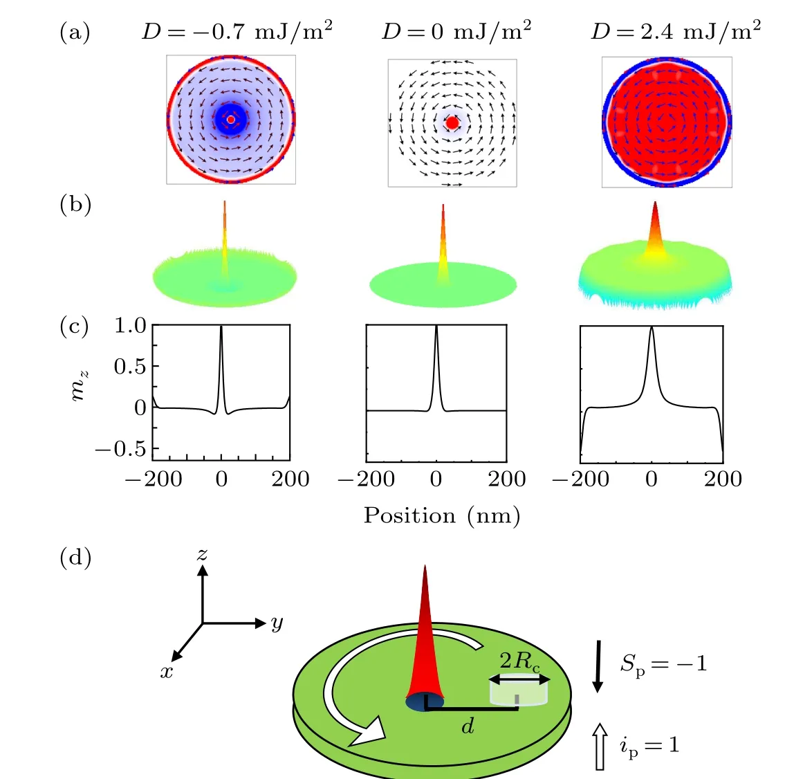
Fig. 1. Magnetization configurations of the vortices under the influence of different D values. (a) Vertical view of the vortex. The arrows represent the in-plane magnetic moment distribution and the red color denotes the+z direction of magnetization mz. (b)Three-dimensional topographs of the outof-plane component mz. (c) Magnetization mz line profile across the vortex nanodisks. (d)Model system of permalloy nanodisk. The ground state of the permalloy nanodisk is a vortex with upward polarity(represented by a cone)and counterclockwise chirality (represented by a white arrow). The spinpolarized current is injected into the permalloy nanodisk through a nanocontact, indicated by a white cylinder with diameter 2Rc. The nanocontact is designed on the y-axis and the distance between its center and the nanodisk center is d.
We first confirm the static magnetization configuration under the influence of DMI,as shown in Fig.1.The simulation shows that the nanodisk can maintain the vortex state between-0.7 mJ/m2≤D ≤2.4 mJ/m2, as shown in Fig. 1(a). Figure 1(b) shows three-dimensional topographs corresponding to the indicatedD, and it is convenient to observe the out-ofplane magnetization. References[3,23],respectively,reported in detail the influence of bulk DMI and interfacial DMI on the magnetization configuration.Reference[3]found that the bulk DMI makes the in-plane and edge magnetization tilt in two different directions,but the in-plane magnetization tilt was much smaller than the edge magnetization tilt.[3]Reference [23]demonstrated that interfacial DMI bends the magnetization at the edges towards the out-of-plane direction.[23]It is obvious that the magnetization configuration shown in Fig. 1 agrees well with Ref. [3]. Figure 1(c) shows themzprofiles of the vortex,and we observe the same features that were described in Ref. [23]. The vortex core is enlarged whenD >0 mJ/m2and it will be compressed whenD <0 mJ/m2.[3]Figure 1(d)presents the model system, where the spin-polarized current is injected via a nanocontact along the out-of-plane direction.The current and its spin-polarization direction are indicated byip=+1 andSp=-1,respectively.
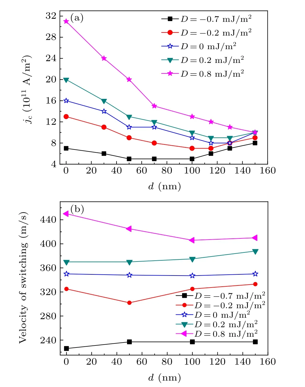
Fig.2. (a)Dependence of critical reversal current density jc on the nanocontact position d and various D. (b) Corresponding reversal velocity of jc shown in(a).
We perform extensive micromagnetic simulation calculations to analyze the reversal features in the presence of DMI.First, the critical reversal current densityjcis explored and the dependence ofjconDand nanocontact positiondis shown in Fig. 2(a). It is observed that the dependence ofjcondpresents a similar changing tendency as in the case of no DMI. Thejcfirst decreases greatly with increasingdand then increases slightly with further increasingd. In addition, different DMI has different effects onjc. Atd=0 nm,jc=16×1011A/m2when DMI is not considered, whereasD=-0.7 mJ/m2makesjcreduce to 7×10¹¹A/m2while its value reaches 31×1011A/m2whenD=0.8 mJ/m2. The largest discrepancy amongjcalso exists atd= 0 nm, and this discrepancy decreases with the increase ind, and the smallest difference appears atd=150 nm. It is worth noting that Fig. 2(a) only showsjcforD ≤0.8 mJ/m2. In fact,the detailed simulation process shows that the magnetic vortex at a largerDwill not exert gyration or reversal but experience nucleation and annihilation of multi-vortices. Therefore, figure 2(a) only illustratesjcfromD=-0.7 mJ/m2toD=0.8 mJ/m2. The simulation shows that the magnetic vortex switches its polarity through the mechanism of V-AV formation and annihilation,[36-40]and this mechanism requires the magnetic vortex to reach the critical reversal velocity.Prior studies have demonstrated that the critical reversal velocity only relates to the internal parameters and its magnitude since permalloy is about 350 m/s.[33,34,41-43]However, as demonstrated in Fig.2(b),the reversal velocity has subtle differences amongd. In contrast, it is significantly affected byD. For example,atd=0 nm,the value of the critical reversal velocity increases from 226 m/s to 450 m/s withDincreasing from-0.7 mJ/m2to 0.8 mJ/m2.
Next,we use Fig.3 to explain the dependence ofjcondandD, as shown in Fig. 2(a). Figure 3 shows the velocity of vortex core steady gyration at variousd. This shows that the velocity still oscillates even when the gyration is stable and oscillation amplitudes increase with increasingd,making it easier for the vortex core to reach the critical reversal velocity.We observe that the changes in velocity withdcan well explain the changes injcwithdby comparing Fig. 3(a) to Fig. 3(b).The velocity reaches the maximum value whend=100 nm atD=-0.2 mJ/m2,corresponding to the minimumjcat this nanocontact positiondin Fig. 2(a). ForD=0.8 mJ/m2, the maximum velocity appears atd=150 nm,leading to the vortex core polarity being switched with the lowest current density. Moreover,except forD=0.8 mJ/m2,the reversal current density of the vortex core increases whendexceeds 100 nm,which is attributed to the decrease in velocity amplitude when it exceeds this distance.
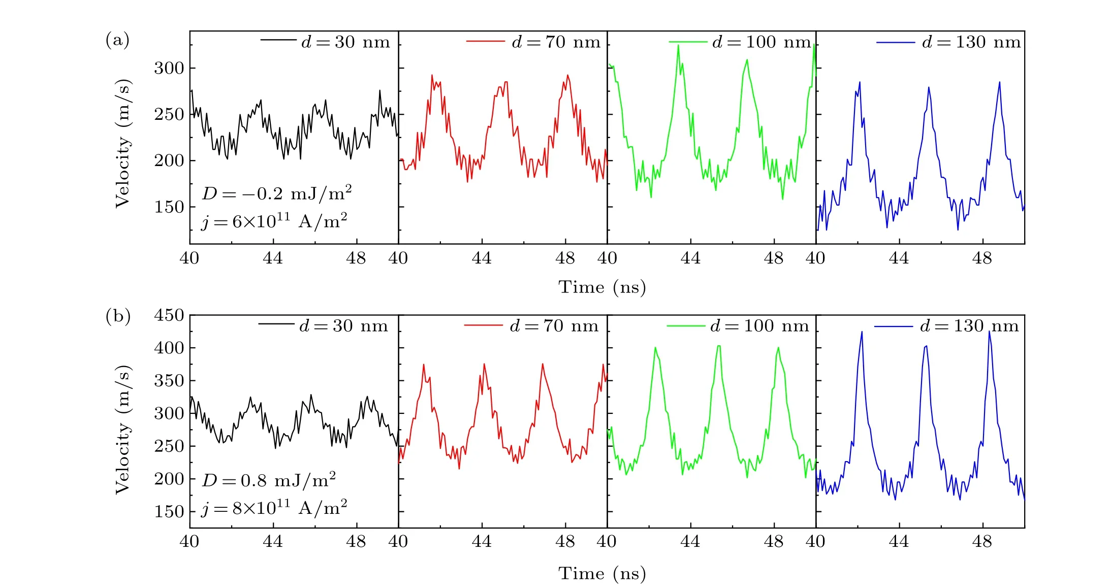
Fig.3. Steady gyration velocity as a function of time for(a)D=-0.2 mJ/m2 and j=6×10¹¹ A/m2;(b)D=0.8 mJ/m2 and j=8×10¹¹ A/m2.
Figure 4 reveals the dependence of switching time on the current densityj,d, andD, which is crucial for vortex core reversal. It is clear that the vortex core needs the longest time to complete its polarity switching whend=0 nm, and the switching time decreases drastically when the nanocontact is moved from the nanodisk center. Figure 4(a) shows that the difference in switching time is minimum atd= 30 nm andd=115 nm. We find that the switching time forjcatD=-0.7 mJ/m2is the longest, which can be ascribed to the minimum reversal current density atD=-0.7 mJ/m2. Based on this information combined with that of Fig. 2(a), we find that the vortex core needs the minimumjto complete its reversal. However, at the same time, its switching time is the longest. Figure 4(b)and the inset show that the switching time decreases with the increasingj. The difference being that the vortex core needs a longer switching time when the nanocontact is closer to the nanodisk center. Furthermore,whendandjare fixed, the vortex needs a longer switching time whenDis larger.
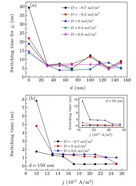
Fig. 4. (a) Switching time of jc for the indicated D and d. (b) Switching time as a function of j at d =150 nm. The inset is the switching time for d=50 nm.
The magnetic vortex reversal mechanism under the influence of DMI is different to the nucleation, growth and displacement of the domain wall reported in multilayer magnetization reversal.[44,45]In the presence of DMI, the magnetic vortex is still reversed by A-AV nucleation and annihilation mechanism. To gain further understanding of the vortex core reversal process and after-reversal configurations,we illustrate the vital steps during the whole reversal process in Fig.5. Figures 5(a)and 5(b)show the reversal process forD=0 mJ/m2andD=-0.7 mJ/m2atj=10×1011A/m2,respectively.Step I is the initial state of vortex cores. We find the vortex core is compressed much smaller and there is a larger circular dip with opposite magnetization surrounding the vortex core induced by DMI(see Fig.5(a1)). After being stimulated by the spin-polarized current,the vortex core begins to gyrate due to the gyroscopic force,and the velocity continuously increases,and thus a V-AV pair forms(see Fig.5(a2)). Afterwards,the anti-vortex annihilates the initial vortex when the velocity approaches the critical velocity (see Fig. 5(a3)), and the vortex with opposite polarity and the same chirality circulation remains. Then,the vortex core rotates in the opposite direction and eventually stays at the position of minimum energy (see Fig.5(a4)). As can be seen from Fig.5(b), it is the existence of the larger dip with the larger negative magnetization in the original configuration that makes it easier to form magnetic vortex pairs under the influence of DMI and thus easier to reverse its polarity. Furthermore, the vortex core expands becoming much larger as a result of it being affected by DMI after reversal.
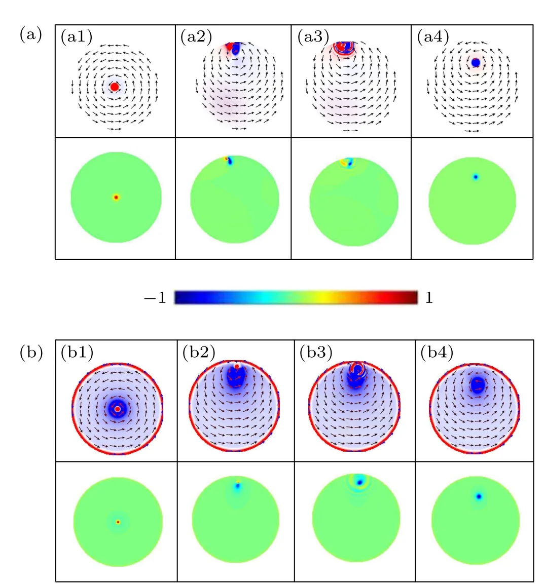
Fig. 5. The first and second rows display images of the magnetization distributions at the different steps from the plane and perspective views, respectively. In the first row, the small arrows indicate the in-plane direction of magnetization. The color of the surfaces in the second row indicates the out-of-plane magnetization normalized by the saturation value,mz/Ms. (a) D=0 mJ/m2 and j =10×1011 A/m2. (b) D=-0.7 mJ/m2 and j=10×1011 A/m2. The inset chronological images represent the initial configuration,gyration,annihilation and final steady state after reversal,respectively.
3. Conclusion and outlook
The presented results in this paper offer vortex core switching features in the presence of Dzyaloshinskii-Moriya interaction using micromagnetic simulation. We explore the vortex core reversal features in the model system with the combination of off-centered nanocontact and the introduction of DMI. We find that the critical switching current density,switching velocity and switching time can be mediated by adjusting the nanocontact positions and Dzyaloshinskii-Moriya interaction strength. These distinct advantages will benefit magnetic vortex-based data storage. In future work, we will continue to change the DMI strength to obtain skyrmions. Exploring the configurations and dynamics of skyrmions is more meaningful for the effects of DMI.
Acknowledgments
Project supported by the National Natural Science Foundation of China(Grant Nos.11774045 and 22078124)and the Program for the Development of Science and Technology of Jilin Province,China(Grant No.20210101410JC).
- Chinese Physics B的其它文章
- Characterizing entanglement in non-Hermitian chaotic systems via out-of-time ordered correlators
- Steering quantum nonlocalities of quantum dot system suffering from decoherence
- Probabilistic quantum teleportation of shared quantum secret
- Spin–orbit coupling adjusting topological superfluid of mass-imbalanced Fermi gas
- Improvement of a continuous-variable measurement-device-independent quantum key distribution system via quantum scissors
- An overview of quantum error mitigation formulas

